

Bosch Solution 2000, Solution 3000 User Manual
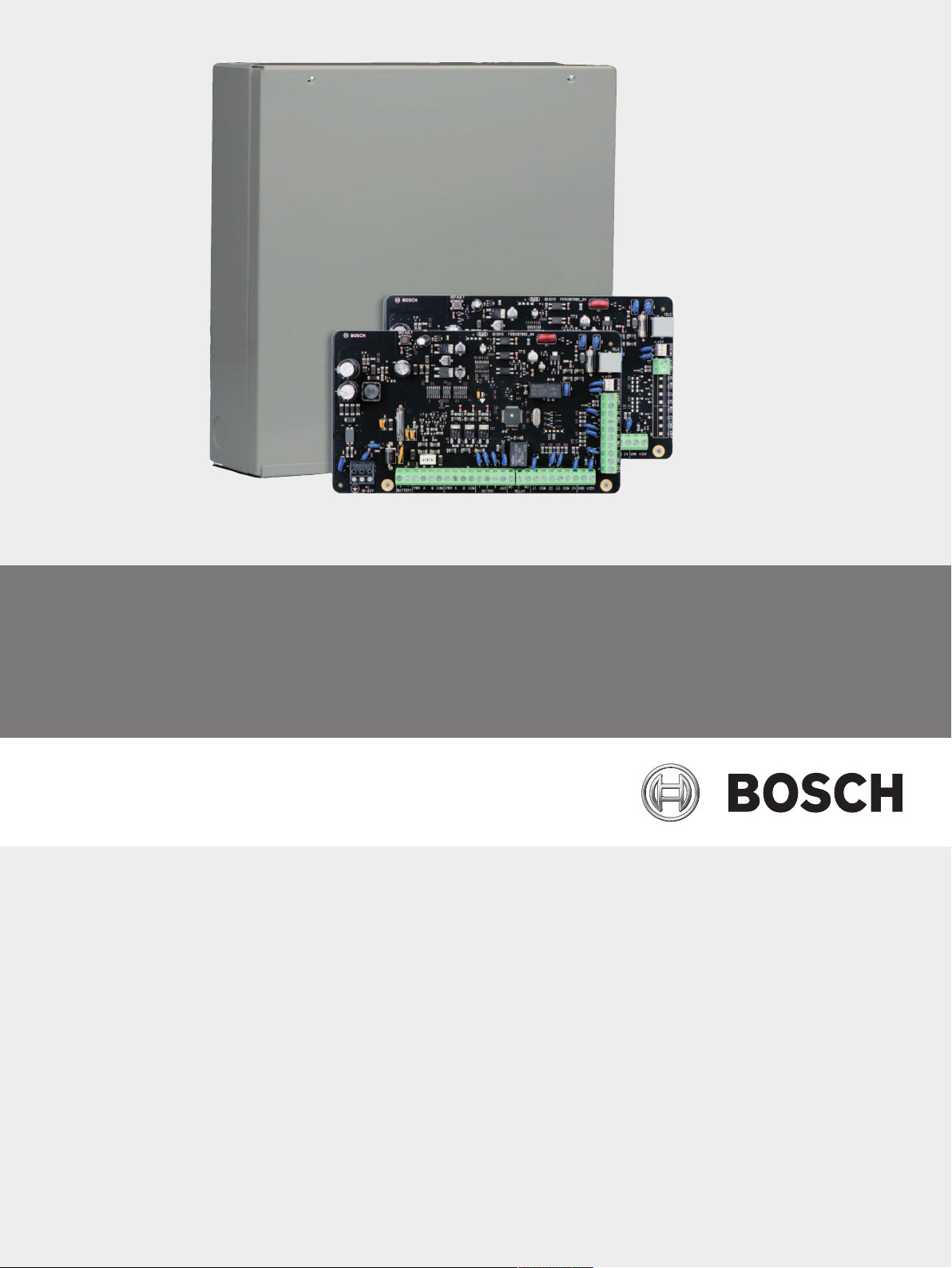
Control Panel
Solution 2000 / 3000
en
User's Guide


Control Panel Table of contents | en 3
Table of contents
1
2
3
3.1 Codepad 7
3.2 Codepad Indicators 7
3.3 Audible Indications 9
4
5
5.1 Arming the System 12
5.1.1 Forced Arming 12
5.1.2 Arming in AWAY Mode 12
5.1.3 Arming in STAY Mode 1 13
5.1.4 Arming in STAY Mode 2 13
5.1.5 Programming STAY Mode 2 Bypass Zones 14
5.2 Disarming the System 14
5.3 Arming/Disarming Areas 14
5.4 User Codes 15
5.4.1 Adding User/Radio Codes 15
5.4.2 Deleting User/Radio Codes 16
5.5 Codepad Alarms 16
5.5.1 Codepad Duress Alarm 16
5.5.2 Codepad Panic Alarm 16
5.5.3 Codepad Fire Alarm 17
5.5.4 Codepad Medical Alarm 17
5.5.5 Codepad PIN Error (Access Denied) 17
5.6 Isolating Zones 17
5.6.1 Standard Isolating 17
5.6.2 Code to Isolate 17
5.7 Fault Analysis Mode 18
5.7.1 Fault Descriptions 19
5.8 Date and Time 20
5.9 Turning Outputs On/Off 20
5.10 Reset Latching Outputs 21
5.11 Telco Arm/Disarm Sequence (Call Forward On/Off) 21
5.11.1 Telco Arm Sequence 21
5.11.2 Telco Disarm Sequence 21
5.12 Testing 22
5.12.1 Horn Speaker Test 22
5.12.2 Bell Test 22
5.12.3 Strobe Test 22
5.12.4 Walk Test Mode 22
5.12.5 Test Report 23
5.13 Event Memory 23
5.14 Day Alarm 23
5.15 Codepad ID / Buzzer Tone 23
5.16 Remote Arming by Telephone 24
5.17 Domestic Dialing 24
5.17.1 Acknowledging Domestic Calls 24
Introduction 5
Specifications 6
Codepad Introduction 7
Operation with TEXT LCD Codepad 10
Operation with ICON LCD Codepad 12
Bosch Security Systems, Inc. User's Guide 2017.09 | 04 | F.01U.298.028

4 en | Table of contents Control Panel
5.17.2 Programming Domestic Telephone Numbers 25
5.17.3 Disable Domestic Dialing 25
6
Glossary of Terms 26
2017.09 | 04 | F.01U.298.028 User's Guide Bosch Security Systems, Inc.

Control Panel Introduction | en 5
1 Introduction
Congratulations on selecting the Solution 2000 / Solution 3000 Control Panel to protect you
and your property. To obtain the most from your unit, take time to read through this manual
and familiarize yourself with the numerous outstanding operating features of this system. In all
aspects of planning, engineering, styling, operation, convenience, and adaptability, we have
sought to anticipate your every possible requirement.
Programming simplicity and speed were some of the major considerations and we believe that
our objectives in this area were more than satisfied.
This manual explains all aspects of operating the control panel. All system parameters and
options are detailed; however, suitability is left up to the individual. Every system can be
tailored to meet all requirements quickly and easily.
Bosch Security Systems, Inc. User's Guide 2017.09 | 04 | F.01U.298.028
6 en | Specifications Control Panel
2 Specifications
Temperature Range 0℃ to +50℃
Humidity 20% to 90%
Power Source TF008 Plug Pack – 240 V/18 VAC @ 1.3A
Stand-By Current 65 mA
Current Draw in Alarm Condition 115 mA
Current Draw in Alarm Condition with
Codepad
Back-Up Battery 7 Ah/12 VDC Rechargeable Sealed Lead Acid
Supplier Code N771
Tab.2.1: Specifications
Notice!
Test the sirens, strobe, and zones at weekly intervals.
105 mA
Battery
2017.09 | 04 | F.01U.298.028 User's Guide Bosch Security Systems, Inc.
Control Panel Codepad Introduction | en 7
1 2 3
4
7
#
8
0
9
5 6
*
1
4
7
2
5
8
3
6
9
STAY
# AWAY
0
*
1 2 3 4 5 6 7 8
ON
OFF
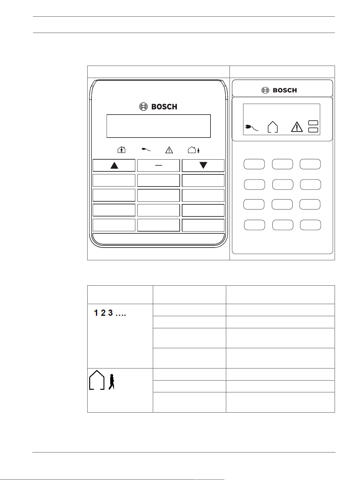
3 Codepad Introduction
3.1 Codepad
IUI – SOL -TEXT IUI – SOL – ICON
3.2 Codepad Indicators
Codepad indicator
icons
ZONE 1 – 8 for
Bosch Security Systems, Inc. User's Guide 2017.09 | 04 | F.01U.298.028
Solution 2000
ZONE 1 – 16 for
Solution 3000
AWAY
Status Definition
On Zone is unsealed.
Off Zone is sealed.
Flashing Fast (0.25 sec
on/0.25 sec off)
Flashing Slow (1 sec on/1
sec off)
On System is armed in AWAY Mode.
Off System is not armed in AWAY Mode.
Flashing twice a sec with
STAY indicator
Zone is in alarm condition.
Zone is manually isolated or selected to
be isolated.
Setting STAY Mode 2 bypass zones.
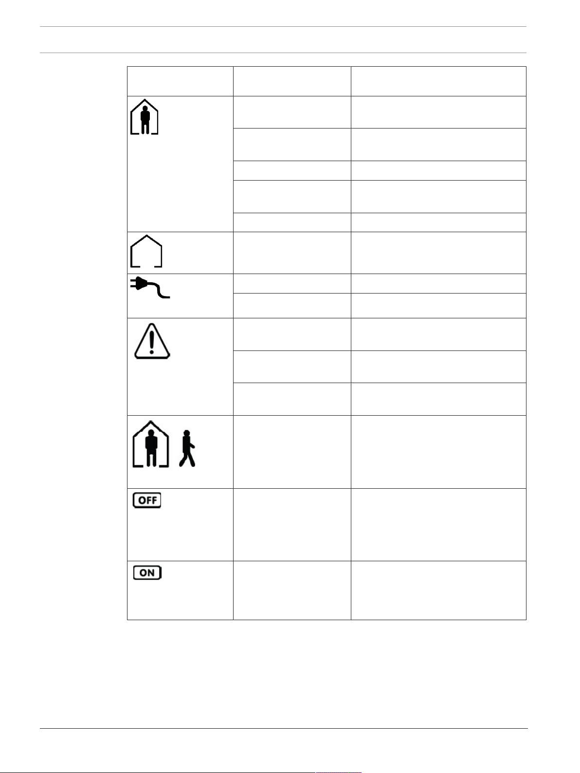
8 en | Codepad Introduction Control Panel
Codepad indicator
icons
STAY
MAINS
Status Definition
On System is armed in STAY Mode 1 or
STAY Mode 2.
Off System is not armed in STAY Mode 1 or
STAY Mode 2.
Flashing twice a sec Zone isolating mode
Flashing twice a sec with
Setting STAY Mode 2 zones.
AWAY indicator
Flashing once every 3 sec Day alarm status – day alarm turned on.
On System is disarmed.
On AC MAINS power normal.
Flashing AC MAINS supply has failed.
On There is a system fault that needs to be
rectified.
FAULTS
Programming Mode
Tab.3.2: Icon Indicators
Off The system is normal, there are no
faults.
Flashing There is a system fault that needs to be
acknowledged.
Flashing These two indicators flash when you
enter Installer’s Programming Mode or
use any Master Code function.
The OFF indicator lights when the
system is disarmed and flashes when a
zone becomes unsealed when
disarmed. The indicator stops flashing
when all zones are sealed.
The ON indicator lights when the
system is armed and flashes when an
alarm occurs. The indicator is reset
after a valid User Code is entered.
2017.09 | 04 | F.01U.298.028 User's Guide Bosch Security Systems, Inc.

Control Panel Codepad Introduction | en 9
3.3 Audible Indications
The table below defines the audible indicators given out by the codepad buzzer.
Audible Indicator Definition
One short beep A button/key was pressed on the codepad, or Exit Time ended
when armed in STAY Mode 1 or STAY Mode 2.
Two short beeps The system accepted your code.
Three short beeps The requested function was executed.
One long beep Indicates the last 10 seconds of Exit Time when armed in AWAY
Mode, or the requested operation was denied or aborted.
Indicates codepad panic/fire/medical alarm operation.
One beep every sec Walk Test Mode is currently active.
One short beep every min There is a system fault waiting to be acknowledged.
One beep every 4 sec. During Auto Arming Pre-Alert Time, the warning before
automatic arming takes place.
One beep every 2 sec. During Exit Time when armed in AWAY Mode.
Tab.3.3: Audible Indicators
Bosch Security Systems, Inc. User's Guide 2017.09 | 04 | F.01U.298.028
 Loading...