

Bosch Solution-16, Solution-16 safecom Quick Reference Manual

Solution-16/
Solution-16 Safecom
Quick Reference Guide
ISSUE 2.41

2 Solution-16/Solution-16
Solution-16/
Safecom
Quick Reference Guide
Solution-16
Safecom
Quick Reference Guide
Copyright 2001 by Bosch Security Systems Pty Limited,
SYDNEY, AUSTRALIA
Document Part Number MA880Q
Document ISSUE 2.41
This documentation is provided to suit both the
Solution-16
Software Version 1.10 = S16_V11 Software Version 1.40 = S16_V4
Software Version 1.20 = S16_V12 Software Version 2.0x = S16_V20
Software Version 1.3x = S16_V13
This quick reference guide includes programming locations to suit both Solution-16 (CC880/LP880) and the
Solution-16 Safecom (SC8016) control panel. Locations that are only relevant when using the SC8016 are
prefixed with the word Safecom.
(CC880/LP880) and
Firmware Revision 2.06
Hardware Revision K
Alarm Link Forms
Solution-16
Safecom (SC8016)
Copyright Notice
All rights reserved. No part of this publication may be reproduced, transmitted or stored in a retrieval system in
any form or by any means, electronic, mechanical, photocopying, recording, or otherwise, without the prior
written perm ission of Bosc h Security Systems Pty Limited.
Trademarks
Throughout this document trademark names may have been used. Rather than put a trademark symbol in every
occurrence of a trademark name, we state that we are using the names only in an editorial fashion and to the
benefit of the trademark owner with no intention of infringement of the trademark.
Notice of Liability
While every precaution has been taken in the preparation of this document, neither Bosch Security Systems Pty
Limited nor any of its official representatives shall have any liability to any person or entity with respect to any
liability, loss or damage caused or alleged to be caused directly or indirectly by the information contained in this
book.
Bosch Secu rity Systems P ty Limited res erves the rig ht to make chan ges to featur es and specifi cations at any
time without prior notification in the interest of ongoing product development and improvement.
SOL 16 SAFECOM QUICK REF GUIDE.DOC.DOC Bosch Security Systems Pty Limited

Solution-16/Solution-16
Safecom
Quick Reference Guide
3
Introduction
Thank you for choosing the Solution control panel for your installation. We a re sure that you will
find this system extremely flexible, reliable and easy to use. The quick reference guide is supplied
with the system to provide users with enough basic information to wire, configure and program the
system. Due to the systems many programmable features and options, we suggest that you obtain
the complete installation manual that provides detailed information on system options and functions
and programming methods.
Programming
The programming options of the system are stored in a non-volatile EPROM. This memory will
hold all information during a total power loss and can be changed as many times as required.
In general, the entire programming sequence will consist of entering a location number and then
change the data as required.
Programming the system can be via the following methods:
• Codepad
• Hand Held Programmer
• Alarm Link Software
Programming Using A Codepad
The system needs to be disarmed (with no active alarm) to program the control panel. If there is
an active alarm or the system is armed, enter the code for User 1 (Default = 2580) followed by the
# key (User Code 1 is factory default as the Master Code).
To enter installer’s programming mode, enter the installer code (Default = 1234) followed by the #
key. Two beeps will be heard. Both the STAY and AWAY indicators will flash simultaneously to
indicate that you have entered programming mode. The codepad indicators will displ ay the curren t
data programmed in LOCATION 000 (First location of the Primary Telephone Number).
To move to another programming location, enter the location number followed by the # key. The
data in the new location will now be displayed via the codepad indicators (Eg. If you entered 52#,
the system will jump you to LOCATION 052 the beginning of the Subscriber ID Number For Area
1).
To move to the next location, press the # key. This will step you to the next location. The data in
the next location will now be displayed via the codepad indicators (Eg. If you are currently
positioned at LOCATION 052, pressing the # key will take you to LOCATION 053).
To step back one location, press the * key (Eg. If you are currently positioned at LOCATION 53,
pressing th e * key will take you back to LO CATION 52).
To change data in the current location, enter the new value (0 – 15) followed by the * key. This will
store the new data into the location and leave you at the same location (Eg. If you enter the value
14*, both the Zone 4 indicator and the MAINS indicator will display to represent the new data
value).
To move to the next location, press the # key. The data in the next location will now be displayed.
To exit Installer’s Programming Mode, enter 960#. Two beeps will be heard and the STAY and
AWAY indicators will no longer display. The system has now returned to the disarmed state and is
now ready for use.
The table below is a quick guide to programming:
Enter Installer’s Programming Mode 1234#
Exit Installer’s Programming Mode 960#
Step To Next Location
Step Back One Location *
Program New Data Into Location Data + * (Data = 0 – 15)
Jump To A New Location
#
Location Number + #
Bosch Security Systems Pty Limited
4 Solution-16/Solution-16
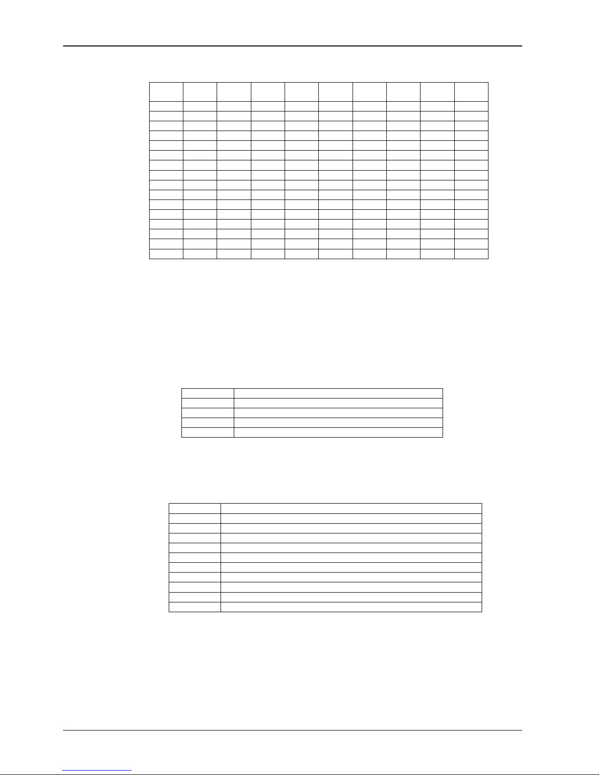
Codepad Indicators
Data
Value
Zone 1
Indicator
0
1
2 X
3
4 X
5
6 X
7
8
9
10
11 X X
12
13 X X
14
15 X X
Zone 2
Indicator
X
X
X
X
X
X X
X
X X
X X
Zone 3
Indicator
Zone 4
Indicator
Zone 5
Indicator
Zone 6
Indicator
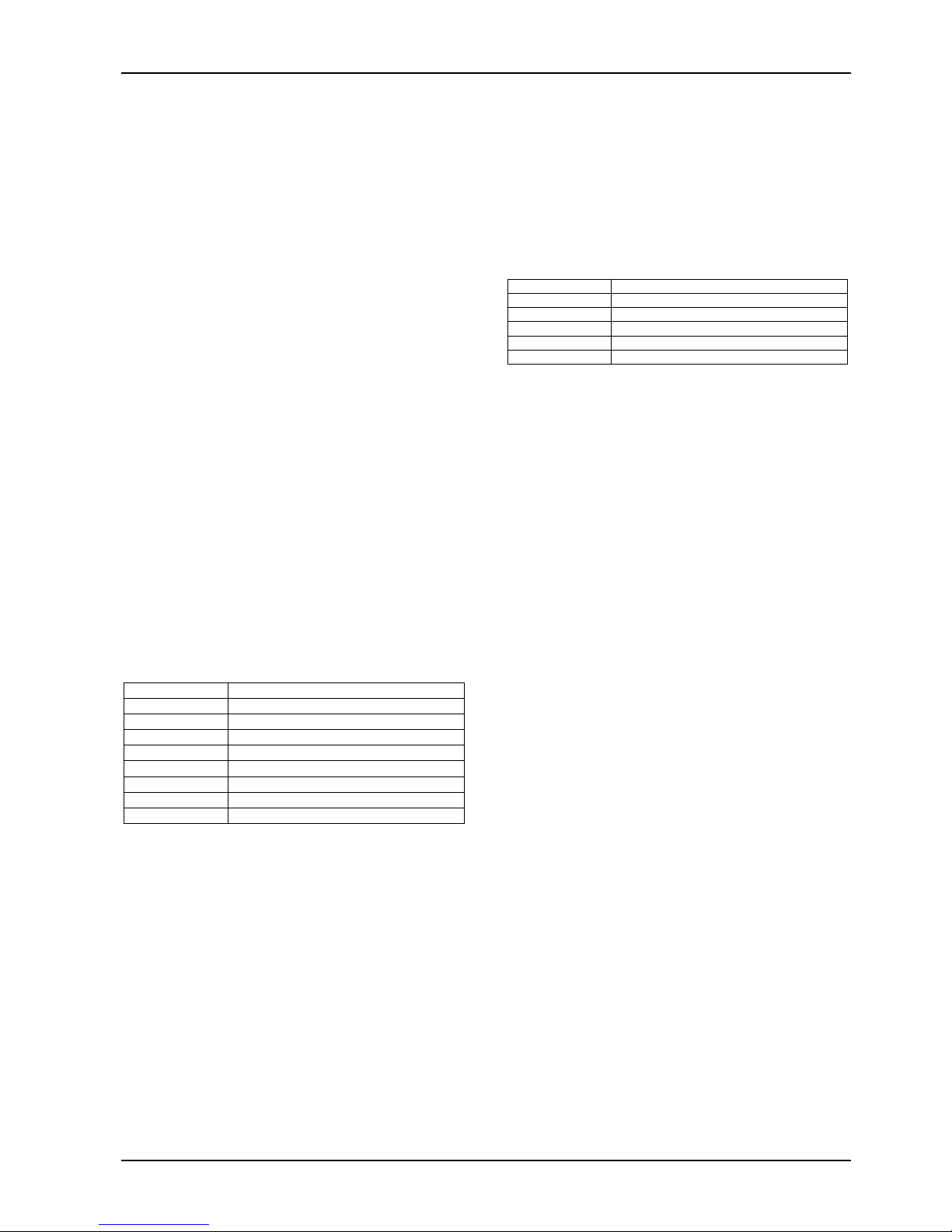
Programming Option Bits
You will notice option bits throughout the quick reference guide. This allows you to program any
combination of the four different options in the one location by adding the options together.
Programming a zero (0) will disable all four options.
Example
If at LOCATION 663 you only want options 1, 2 and 4, add the numbers together and the total is
the number to be programmed. In this example, the number to be programmed is 7 (Eg. 1 + 2 + 4
= 7).
Option Description
1 Dialler Reporting Functions Allowed
2
4 Upload/Download Via Alarm Link Allowed
8
Remote Arming Via Telephone Allowed
Terminate Alarm Link Session On Alarm
Installer’s Programming Commands
These commands can only be used when you enter Installer’s Programming Mode. Enter the
command followed by the # key.
Command Description
958
959 Test Programming Key
960
961
962
963
964 Erase Programming Key
965
966 Enable/Disable Automatic Stepping Of Locations When Programming
999
Enable/Disable Zone Status (Hand Held Programmer Required)
Exit Installer’s Programming Mode
Default System Back To Factory Settings
Copy Panel Memory To Programming Key
Copy Programming Key To Panel Memory
Default System For Domestic Dialling Format
Display Software Version (Hand Held Programmer Required)
Safecom
Zone 7
Indicator
Quick Reference Guide
Zone 8
Indicator
MAINS
Indicator
SOL 16 SAFECOM QUICK REF GUIDE.DOC.DOC Bosch Security Systems Pty Limited

Solution-16/Solution-16
Safecom
Arming The System (On)
AWAY Mode
Press and hold the # key until two beeps are
1.
heard.
Or
2. Enter your code followed by the # key.
[eg. 2580 + #].
STAY Mode 1
1. Press and hold the * key until two beeps are
heard.
Or
Enter your code followed by the * key.
2.
[eg. 2580 + *].
STAY Mode 2
1. Press and hold the 0 key until two beeps are
heard.
Arm All Areas In AWAY Mode (Partitioning)
1. Enter your code followed by 0 and then the #
key [eg. 2580 + 0 + #].
This function allows a code to arm all areas that the
code is assigned to in AWAY Mode at the same time
without the need to arm each area individually.
Disarming The System (Off)
AWAY Mode
1. Enter your code followed by the # key.
[eg. 2580 + #].
STAY Mode 1
Press and hold the * key until two beeps are
1.
heard (Only if no alarm).
Or
2. Enter your code followed by the # key.
[eg. 2580 + #].
STAY Mode 2
Press and hold the 0 key until two beeps are
1.
heard (Only if no alarm).
Or
Enter your code followed by the # key.
2.
[eg. 2580 + #].
Quick Reference Guide
Disarm All Areas (Partitioning)
1. Enter your code followed by 0 and then the #
key [eg. 2580 + 0 + #].
This function allows a code to disarm all areas that
the code is assigned to at the same time without the
need to disarm each area individually.
Isolating Zones
Standard Isolating
Press the * key twice.
1.
2. Enter the zone number that you want to
isolate followed by the * key.
Repeat step 2 if more than one zone is
required to be isolated.
3. Press the # key to exit when finished.
Code To Isolate
Press the * key once.
1.
Enter your user code.
2.
3. Enter the zone number that you want to
isolate followed by the * key.
4. Repeat step 2 if more than one zone is
required to be isolated.
5. Press the # key to exit when finished.
5
Bosch Security Systems Pty Limited

6 Solution-16/Solution-16
Set First Test Report
1. Enter the Installer Code followed by 2 and the
key [eg. 1234 + 2 + #].
2. Enter the Number Of Days (0 - 99) to wait
until first test report followed by the # key.
Event Memory Recall
1. Enter the Installer Code or Master Code
followed by 3 and the # key.
[eg. 1234 + 3 + #].
The last 40 events (non partitioned) or last 10 events
(partitioned) will be displayed in reverse order (i.e.
most recent to least recent).
Walk Test Mode
Enter the Installer Code or Master Code
1.
followed by 4 and the # key.
[eg. 1234 + 4 + #].
2. Test each zone as required.
Press the # key to exit.
3.
Satellite Siren Service Mode
1. Enter the Installer Code followed by 5 and the
# key [eg. 1234 + 5 + #].
Telephone Monitor Mode (Toggle On/Off)
1. Enter the Installer Code followed by 7 and the
# key [eg. 1234 + 7 + #].
2. Press and hold the 9 key until two beeps are
heard to send a test report.
3. Repeat Step 1 to turn telephone monitor
mode off when complete.
Zone LED Dialling Event
1
2
3 Handshake Received
4
5 Kiss-Off Received
None
Telephone Line Seized
Dialling Telephone Nu mber
Data Being Sent
Released Telephone Line
Add A User Code
1. Enter the Master Code followed by 1 and the
# key [eg. 2580 + 1 + #].
Delete A User Code (V1.10)
1. Enter the Master Code followed by 1 and the
# key [eg. 2580 + 1 + #].
2. Enter the User Number that you want to
delete followed by the # key.
3. Press the # key again to delete the user code.
Delete A User Code (V1.20+)
1. Enter the Master Code followed by 1 and the
# key [eg. 2580 + 1 + #].
Enter the User Number that you want to
2.
delete followed by the # key.
Press the * key to delete the user code.
3.
Change Domestic Telephone Numbers
1. Enter the Master Code followed by 2 and the
# key [eg. 2580 + 2 + #].
2. Enter the digits for the telephone number.
3. If more than one telephone number, press the
* key and repeat Step 2, else press the # key
to exit.
Turn Outputs On/Off
1. Enter the Master Code followed by 5 and the
# key [eg. 2580 + 5 + #].
2. Enter the Output Number (1 – 5) that you
want to toggle on or off.
Press the # key to toggle On or the * key to
3.
toggle Off.
Press the # key to exit.
4.
Setting Date and Time
1. Enter the Master Code followed by 6 and the
# key [eg. 2580 + 6 + #].
2. Enter the day (DD), month (MM) and year
(YY) followed by the hour (HH) and minute
(MM).
Press the # key to exit.
3.
2. Enter the User Number that you want to
add/change followed by the # key.
3. Enter the New Code followed by the # key.
Safecom
Quick Reference Guide
SOL 16 SAFECOM QUICK REF GUIDE.DOC.DOC Bosch Security Systems Pty Limited
Solution-16/Solution-16
Safecom
Quick Reference Guide
Day Alarm – Toggle On/Off (V1.10)
1. Enter the Master Code followed by 7 and the
# key [eg. 25 80 + 7 + #].
Day Alarm – Toggle On/Off (V1.20+)
Press and hold the 4 key until two beeps are
1.
heard.
STAY Mode 2 Zones - Program
1. Enter the Master Code followed by 8 and the
# key [eg. 25 80 + 8 + #].
2. Enter the Zone Number that you want the
system to automatically isolate followed by the
* key.
Repeat if more than one zone to be
3.
automatically isolated when armed in STAY
Mode 2.
4. Press the # key to terminate.
Fault Analysis
Press and hold the 5 key until two beeps are
1.
heard.
Zone Indicators will display FAULT condition
2.
(see table below).
Press # key to terminate.
3.
Zone LED FAULT Condition
1
2
3
4
5
6 EPROM Fail
7
8 Communication Fail
Battery Low
Date / Time Reset
Sensor Watch Fail
Horn Speaker Fail
Telephone Line Fail
Zone 16 In Alarm (Partitioning)
Modem Call (Alarm Link)
1. Press and hold the 6 key until two beeps are
heard.
Latching Outputs (Reset)
1. Press and hold the 7 key until two beeps are
heard.
7
Codepad ID / Buzzer Tone
1. Press and hold the 8 key until the desired
buzzer tone has been reached.
If the system has been partitioned, the
codepad will display a number to identify
which area the codepad belongs to (see table
below).
Press the # key to terminate.
2.
Zone LED Codepad Assignment
1
2 Area 2
3
4
7
Area 1
Area 3
Area 4
Master Partitioned Codepad
Test Report
1. Press an d hold the 9 key unt il two beeps are
heard.
Speaker Test
1. Press an d hold the 1 key unt il two beeps are
heard. The horn speaker will sound for two
seconds.
Bell Test
Press and hold the 2 key until t wo beeps are
1.
heard. The piezo will sound for two seconds.
Strobe Test (Toggle On/Off)
Press and hold the 3 key until three beeps are
1.
heard to turn the strobe on.
Press and hold the 3 key until t wo beeps are
2.
heard to turn the strobe off.
Bosch Security Systems Pty Limited
8 Solution-16/Solution-16
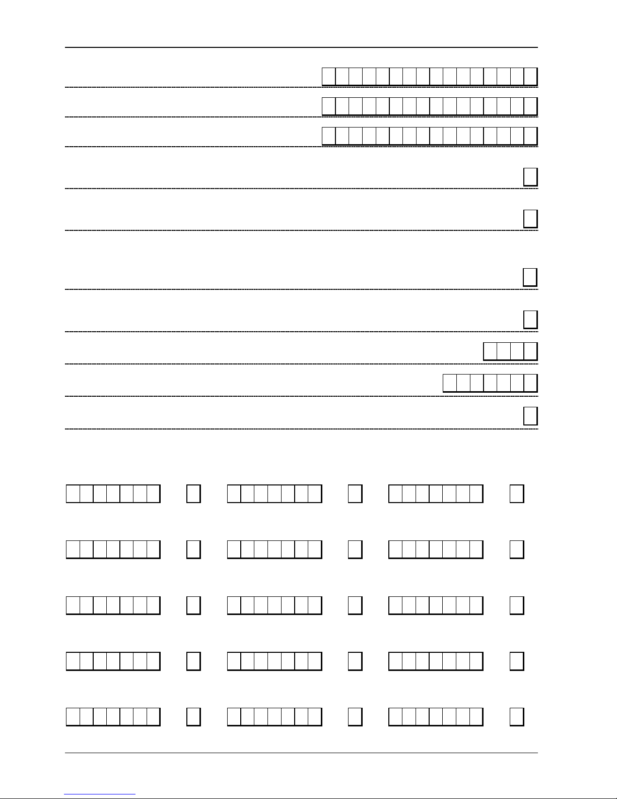
Location 000 – 015
Primary Telephone Number
(0=10 and telephone termination = 0, anywhere else 0=0)
Location 016 – 031
Secondary Telephone Number
(0=10 and telephone termination = 0, anywhere else 0=0)
Location 032 – 047
Call Back Telephone Number
(0=10 and telephone termination = 0, anywhere else 0=0)
Location 48
Dialling Format
Location 49
Handshake Tone
Location 50
Transmission Format
Location 51
Transmission Speed
Location 052 – 055
1 = Australian DTMF 4 = International DTMF
2 = Australian Decadic 5 = Reversed Decadic
3 = Alternate DTMF & Decadic (Aust) 6 = Alternate DTMF & Reversed Decadic
1 = HI-LO Handshake (Contact ID) 4 = No Handshake
2 = 1400 Hz (Ademco TX @ 1900 Hz) 5 = Pager
3 = 2300 Hz (Sescoa TX @ 1800 Hz)
1 = Contact ID 6 = 4 + 1 Pulsed Expanded 11 = Domestic
2 = 4 + 2 Expressed 7 = 3 + 1 Pulsed Universal 12 = Basic Pager
3 = 4 + 2 Pulsed 8 = 3 + 1 Pulsed Expanded 13 = Reserved
4 = 4 + 2 Pulsed + Checksum 9 = Reserved 14 = PET Alpha Pager
5 = 4 + 1 Pulsed + Universal 10 = Reserved 15 = Synthesised Voice
1 = 1 Pulse / Second 4 = 20 Pulses / Second
2 = 10 Pulses / Second 5 = 20 Pulses / Second FDL
3 = 15 Pulses / Second 6 = 40 Pulses / Second
000000000 0 0 0 0 000
000000000 0 0 0 0 000
000000000 0 0 0 0 000
Subscriber ID Number For Area 1
Safecom
Quick Reference Guide
1
1
1
2
0 0 0 0
Location 056 – 062
Installer Code
Location 063
Ring Count
Location 064 – 319
0 = Panel Will Not Answer 14 = Answering Machine Bypass 2 (V1.37+)
1 – 13 = No Of Rings Until Panel Answers 15 = Answering Machine Bypass 1
1 2 3 4 15 15 15
8
User Codes
Authority
User Code 1
Location 064 - 070 071 Location 072 - 078 79 Location 080 - 086 87
Level
User Code 2
Authority
Level
User Code 3
Authority
Level
2 5 8 0 15 15 15 8 15 15 15 15 15 15 15 0 15 15 15 15 15 15 15 0
Authority
User Code 4
Location 088 - 094 095 Location 096 - 102 103 Location 104 - 110 111
Level
User Code 5
15 15 15 15 15 15 15 0 15 15 15 15 15 15 15 0 15 15 15 15 15 15 15 0
Authority
Level
User Code 6
Authority
Level
Authority
User Code 7
Location 112 - 118 119 Location 120 - 126 127 Location 128 - 134 135
Level
User Code 8
15 15 15 15 15 15 15 0 15 15 15 15 15 15 15 0 15 15 15 15 15 15 15 0
Authority
Level
User Code 9
Authority
Level
Authority
User Code 10
Location 136 - 142 143 Location 144 - 150 151 Location 152 - 158 159
Level
User Code 11
15 15 15 15 15 15 15 0 15 15 15 15 15 15 15 0 15 15 15 15 15 15 15 0
Authority
Level
User Code 12
Authority
Level
User Code 13
Location 160 - 166 167 Location 168 - 174 175 Location 176 - 182 183
Authority
Level User Code 14
0 0 0 0 0 0 0 0 15 15 15 15 15 15 15 0 15 15 15 15 15 15 15 0
Authority
Level User Code 15
Authority
Level
SOL 16 SAFECOM QUICK REF GUIDE.DOC.DOC Bosch Security Systems Pty Limited
 Loading...