

Bosch Solution 144 User Manual
Solution 144
Security Systems
EN
User Guide
Security System
Solution 144
User Guide
Copyright Notice
Unless otherwise indicated, this publication is the copyright
of Bosch Security Systems Pty Ltd (“Bosch”). All rights are
reserved.You may download a single copy of this publication.
By downloading the publication you agree that you will: (i) only
use the publication for your own reference; (ii) not commercially
exploit or charge any person for the use of the publication;
and (iii) not modify the publication in any way without the
prior written permission of Bosch. Except as specied above or
where authorised by the Copyright Act 1968 (Cth), no part of
this publication may be reproduced, transmitted, modied or
stored in any form or by any means, without the prior written
permission of Bosch.
Trademarks
Throughout this document trademark names may have been
used. Rather than put a trademark symbol in every occurrence
of a trademark name, we state that we are using the names only
in an editorial fashion and to the benet of the trademark owner
with no intention of infringement of the trademark.
Notice of Liability
While every eort has been taken the accuracy of this document,
neither Bosch Security Systems Pty Ltd nor any of its ocial
representatives shall have any liability to any person or entity
with respect to any liability, loss or damage caused or alleged
to be caused directly or indirectly by the information contained
in this book. Should you nd any error on inconsistency, please
notify us accordingly.
Warnings
1) This product must be installed by a qualied and
licensed security installer.
2) This product may not perform as expected if
installed incorrectly.
3) Some features of this product, including but
not limited to Back to Base reporting, SMS and
Email Reporting and Automatic Time and Date
Adjustments require a working telephone line to
operate and telephone communication service
provider charges are applicable.
4) Australian standard AS 2201 requires regular
service by qualied and licensed security persons
and regular user testing. Please consult your
security alarm company for further details.
5) Incorrect programming of parameters can result
in operation contrary to what may be desired.
6) Leave the mains adapter plugged in at all times.
7) Leave the telephone line plugged in at all times
under normal conditions.
8) The Product Identication Label for this product
which is supplied in the resistor pack, must be
axed to the outside of the enclosure during
installation.
Solution 144
Intrusion Control Panel
Bosch Security Systems Pty Ltd reserves the right to make
changes to features and specications at any time without prior
notication in the interest of ongoing product development and
improvement.
Telepermit Note
The grant of a Telepermit for a device in no way indicates Telecom
acceptance of responsibility for the correct operation of that
device under all operating conditions.
This equipment shall not be used in any manner that could
constitute a nuisance to other Telecom customers.
Immediately disconnect this equipment should it become
physically damaged, and arrange for its disposal or repair.
The transmit level from this device is set as a xed level and because
of this there may be circumstances where the performance is less
than optimal. Before reporting such occurrences as faults, please
check the line with a standard telepermitted telephone.
N12138
TELEPERMIT
N12138
TELEPERMIT
This Bosch Solution 144
CC600B Alarm System
may be connected to the
Telecom Network
PTC 211 / 12 / 017
9) This equipment shall not be set up to make
Made In
Australia
RN = 0.5
automatic calls to the Telecom ‘111’ Emergency
Service.
Notice to Owner
Thankyou for selecting the Solution 144 Security Control Panel for your security needs. Your system includes many advanced
features and functions which will be programmed and congured by your security consultant during installation. Depending on the
conguration, and your access level, you may have the ability to program certain features within the system to suit changes in your
security needs. For example you may wish to change a User Name or PIN number when a sta member leaves.
This manual explains all aspects of system operation as well as detailling the various programming options available to you. We ask that
you take the time to read this manual carefully and that you have your installer explain the basic system operation and conguration
to you when the installation is complete.
2 Bosch Security Systems 04/12 BLCC600U

Notice to Owner ........................................................................... 2
Program Menu Tree ..................................................................... 4
Introduction ................................................................................. 5
Features ......................................................................................... 5
User’s Guide .................................................................................. 5
Reporting Alarms ........................................................................ 6
About the Keypad ....................................................................... 6
Keypad Keys ........................................................................... 6
Status Icons / LED’s ................................................................ 7
Keypad Tones ......................................................................... 7
Basic System Operation .............................................................. 8
Turning An Area All On ......................................................... 8
Turning An Area Part On / Part 2 On .................................. 8
Turning The System O ........................................................ 8
Silencing Alarms .................................................................... 9
Automatic Arming ................................................................. 9
Remote Arming - Quick Arm ............................................... 9
DTMF Control Functions ...................................................... 9
Programming Text Using The Keypad ............................. 10
Duress or Silent Alarms ...................................................... 10
System Programming ............................................................... 10
Erase User ......................................................................................10
PIN Numbers ........................................................................11
Change Own PIN ........................................................................11
Change Other PIN ......................................................................11
Add PIN ..........................................................................................11
Delete PIN .....................................................................................12
Tokens ....................................................................................12
Add Token ..................................................................................... 12
Delete Token ................................................................................12
Token Status .................................................................................12
Edit Token ......................................................................................13
RF Keyfob .............................................................................. 13
Add Keyfob ...................................................................................13
Delete Keyfob ..............................................................................13
User Name .....................................................................................13
Area Assignment ........................................................................14
User Options.................................................................................14
TimeZones ............................................................................14
TimeZone Access ........................................................................14
Door Assignment .......................................................................15
User Expire Date ..........................................................................15
Fingerprints .......................................................................... 15
Add Fingerprint ...........................................................................16
Delete Fingerprint ......................................................................16
Fingerprint Status .......................................................................16
Areas ...................................................................................... 16
Area Status ....................................................................................16
Turn Area On/O ........................................................................17
Turn All Areas On ........................................................................17
Turn All Areas O ........................................................................17
Move To Area ................................................................................17
Chime On/O ....................................................................... 18
Chime Mode ......................................................................... 18
Area Name ....................................................................................18
Part Mode 1 Name .....................................................................19
Part Mode 2 Name .....................................................................19
Auto Arming .................................................................................19
Exit Time ........................................................................................20
Entry Time 1 ..................................................................................20
Entry Time 2 ..................................................................................20
Part Entry Time ............................................................................ 21
Inputs ..................................................................................... 21
Zone Status ...................................................................................21
Solution 144 User Guide
Contents
Bypass Zones ...............................................................................21
Set Chime Zones .........................................................................22
Set Part 2 Zones ..........................................................................22
Smoke Sensor Reset .................................................................. 23
Zone Name ...................................................................................23
Walk Test All Zones .....................................................................23
Walk Test A Single Zone ...........................................................23
Outputs ................................................................................. 24
Output Status...............................................................................24
Turn Output On/O ...................................................................24
Output Array ................................................................................25
Door Status ...................................................................................25
Door Array .....................................................................................25
Door Override .............................................................................. 26
Output Name ...............................................................................26
Door Name ...................................................................................26
External Siren Test ............................................................... 27
Internal Siren Test ................................................................ 27
Strobe Test ............................................................................ 27
Communication / Reporting..............................................27
Call/Answer RAS..........................................................................28
Call Forward On/O ...................................................................28
Check Web Email ........................................................................28
Email System Log .......................................................................28
Start Direct Connect .................................................................. 28
Voice Setup ........................................................................... 28
Register Customer ......................................................................28
Destination 1 ................................................................................28
Destination 2 ................................................................................29
Call Forward On ..........................................................................29
Call Forward O ..........................................................................30
User RAS PIN ......................................................................... 30
Email Reporting ................................................................... 30
Email Address ..............................................................................30
Email Options...............................................................................31
Send Test Report .........................................................................31
Devices and Optional Modules ......................................... 31
Device Status ...............................................................................31
Volume ...........................................................................................31
Contrast..........................................................................................32
Backlight ........................................................................................ 32
Name ...............................................................................................32
Trigger Table 1 .............................................................................32
Trigger Table 2 .............................................................................33
SMS Control ..................................................................................33
System Events ......................................................................34
Panel Status ..................................................................................34
System Trouble ............................................................................34
History Log............................................................................ 36
Set Date & Time .................................................................... 36
Volume ...........................................................................................37
TimeZones ............................................................................37
Name ...............................................................................................37
Time .................................................................................................37
Day ................................................................................................... 38
Options...........................................................................................38
Name ...............................................................................................38
Start / Stop Day ...........................................................................38
Keypad Hi/Lo Temp....................................................................39
Site Name ......................................................................................39
Walk Test All Zones .....................................................................39
Battery Test ...................................................................................40
Installation Details .................................................................... 41
3Bosch Security Systems 04/12 BLCC600U

Solution 144
User Guide
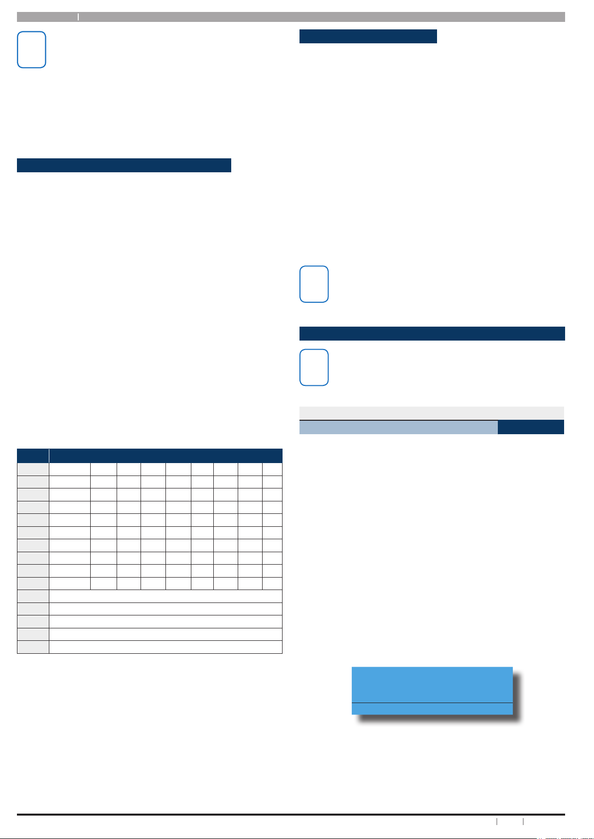
Program Menu Tree
Table 1: shows all of the system options in a tabular format. Each option can be access by pressing the Menu key and
then drilling down using the arrow and OK keys until the required option is listed on the display. A quick way to jump to
a particular option is to press the Menu key followed by the specic option number. You may be asked to enter your PIN
when accessing some options and some options are only available to users with Master Code authority.
Example:
To change the exit time, enter programming mode, then enter [MENU] + [2] + [8] + [0] and follow the on screen prompts.
1 Access 2 Areas 3 Inputs 4 Outputs
1-0 Commands 2-0 Commands 3-0 Command 4-0 Commands
1-0-0 Erase User 2-0-0 Area Status 3-0-0 Zone Status 4-0-0 Output Status
1-1 PIN Codes 2-0-2 Turn All Areas On 3-0-3 Set Chime Zones 4-0-2 Output Array
1-1-0 Change Own PIN 2-0-3 Turn All Areas O 3-0-4 Set Part 2 Zones
1-1-1 Change Other PIN 2-0-4 Move To Area 3-0-5 Smoke Sensor Reset 4-0-4 Door Array
1-1-2 Add PIN 2-0-5 Chime On/O 4-0-5 Door Override
1-1-3 Delete PIN 2-0-6 Chime Mode 3-1 Zone Properties
1-2 Token 2-1 Area Properties 4-1-0 Output Name
1-2-0 Add Token 2-1-0 Area Name 3-9 Input Testing
1-2-1 Delete Token 2-1-6 Part Mode 1 Name 3-9-0 Walk Test All Zones 4-2 Door Control
1-2-2 Token Status 2-1-7 Part Mode 2 Name 3-9-1 Walk Test A Zone 4-2-0 Door Name
1-2-3 Edit Token 2-1-8 Auto Arming
1-3 RF Keyfob 2-8 Timers 4-9-0 External Siren Test
1-3-0 Add Keyfob 2-8-0 Exit Time 4-9-1 Internal Siren Test
1-3-1 Delete Keyfob 2-8-1 Entry Time 1 4-9-2 Strobe Test
1-4 User Properties 2-8-3 Part Entry Time
1-4-0 User Name
1-4-1 Area Assignment
1-4-2 User Options
1-4-4 TimeZone Access
1-4-5 Door Assignment
1-4-6 User Expire Date
2-0-1 Turn Area On/O 3-0-2 Bypass Zones 4-0-1 Turn Output On/O
4-0-3
3-1-0 Zone Name 4-1 Output Properties
4-9 Output Testing
2-8-2 Entry Time 2
Door Status
1-8 Fingerprint
1-8-0 Add Fingerprint
1-8-1 Delete Fingerprint
1-8-2 Fingerprint Status
5 Comms 6 Devices 7 System
5-0 Commands 6-0 Commands 7-0 Commands
5-0-1 Call/Answer RAS 6-0-0 Device Status 7-0-0 Panel Status
5-0-2 Call Forward On/O 6-0-7 Keypad Volume 7-0-1 System Trouble
5-0-3 Check Web Email 6-0-8 Keypad Contrast 7-0-2 History Log
5-0-4 Email System Log 6-0-9 Keypad Backlight 7-0-6 TimeZone Array
5-0-5 Start Direck Link
5-0-6 Voice Setup 6-1 Keypads & Readers 7-1 Clock
5-0-8 Register Customer 6-1-0 Keypad Name 7-1-0 Set Date & Time
5-1 Telephone Numbers 7-4 Siren
5-1-1 Destination 1 6-5 GSM/GPRS Module 7-4-2 Volume
5-1-2 Destination 2 6-5-0 GSM/GPRS Status
5-1-6 Call Forward On 6-5-5 Trigger Table 1 7-5 TimeZones
5-1-7 Call Forward O 6-5-6 Trigger Table 2 7-5-0 Name
5-5 MyAlarm 7-5-2 Day
5-5-8 Email Address 7-5-3 TimeZone Options
5-5-9 Email Options
5-9 Comms Test 7-6-0 Holiday Name
5-9-0 Send Test Report 7-6-1 Start Stop Dates
6-5-7 SMS Control 7-5-1 Time
7-6 Holidays
7-7 System Options
7-7-3 Keypad Hi/Lo Temp
7-7-7 Site Name
7-9 System Testing
7-9-0 Walk Test All Zones
7-9-1 Battery Test
Table 1: Control Panel Menu Tree
4 Bosch Security Systems 04/12 BLCC600U

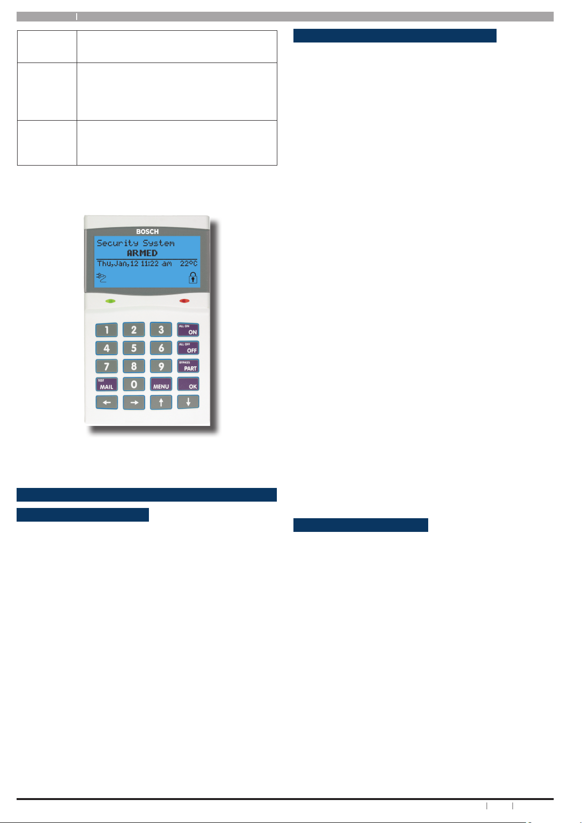
Introduction
Your system helps to secure life, property and investments
against re, theft and bodily harm. It consists of a keypad
(or keypads), sensors such as motion detectors or devices
located on doors and windows, and other sensing devices
designed to detect the presence of smoke or combustion.
The location and quantity of sensing devices will have
already been discussed with you by your alarm installer.
Control of your security system is achieved through
the unique graphic keypad, which displays all system
information in written text and graphical symbols. Its
versatility and ease of operation, make it ideal for any home
or business application.
Features
Listed below are the main features of the Solution 144
control panel.
Up to 144 Fully Programmable Zones
Up to 16 Access Doors
Fire Alarm Verication
Up to 256 User PINs
Up to 37 Programmable Outputs
Email and SMS Alarm Reporting
Optional Fingerprint Readers
Supervised Siren Driver
16 Programmable TimeZones
Up To 8 Areas (Common Area Programmable)
Built-In Dialer
Up To 16 Fully Supervised Keypads / Readers
National Broadband Network / IP Ready
Keyswitch Input (Programmable)
1000 Event History Memory
EMI / Lightning Transient Protection
Programmable Via Keypad
Remote Programmable Via RAS Software
Automatic Test Reports
Built-In Telephone Line Fail Monitor
User’s Guide
Solution 144 User Guide
should create a dierent PIN code for them if this has not
been done by your installer. This guide will explain how to
do this. See “MENU 1-1-2” on page 11.
Please take the time to familiarise yourself with the
following terms before reading the rest of this guide.
Zones
A ‘Zone’ is a detection device, or group of devices connected
to your security system. Zones are identied by the area
they monitor, such as a front door, bedroom window or
hallway.
Faulted Zones
When a zone (such as a door or window) is closed, it is
said to be ‘normal’. When the door or window is open, the
zone is said to be ‘faulted’. When you turn your system
on, you will usually want all of the zones in your system
to be normal, although, you can turn your system on with
faulted zones.
Zones Types
There are two basic types of zones, Non 24-hour and 24hour. See below.
Non 24-Hour Zones
Non 24-hour zones respond to alarm conditions
depending upon whether the system is turned on or o.
They are programmed to either respond instantly to alarm
conditions or to provide a delay for you to reach the keypad
and turn the system o. Various zones will be located
throughout your premises.
When you turn your system on, you have the option of
turning on all zones (All On), or just some of the zones (Part
On). Refer to the basic system operation section for more
information.
Bypassed Zones
A zone which has been bypassed will remain unarmed
when the system is armed. You may need to bypass a
zone when doing renovations in the building or if a sensor
becomes faulty. Bypassed zones will reset the next time
the system is disarmed.
This user’s guide shows you how to use and maintain
your security system. It covers basic functions, such as
turning the system on and o as well as some general
programming. More complex programming and system
conguration should be performed by your installer.
Many of the programming functions described in this
guide will have already been programmed by your alarm
installer while others may need to be programmed or
changed by you. Depending on your particular system
conguration some features described in this manual
may not be available. Please discuss this with your alarm
installer.
Functions outlined in this user guide may require you to
enter your PIN (Personal Identication Number), so make
sure you choose a number that is easy for you to remember
but hard for someone else to guess. For security reasons
do not write this PIN down or give it to anyone else. If more
than one person needs to operate the system then you
24-Hour Zones
24-hour zones are always on and cannot be turned o,
even when the system is turned o (disarmed). There are
two types of 24-hour zones, re zones and non-re zones.
What Is An Area?
The control panel comes defaulted and programmed for a
single area conguration (Area 1), therefore, all zones are
assigned to Area 1. The alarm system can be divided into 8
individual areas. In this case, the security company would
assign dierent sensors (zones) to each area according to
the area they belong.
Example:
Partitioning a commercial business to 4 individual areas
may be as follows:
Area 1 – Main entry/exit area
Area 2 – Sales
5Bosch Security Systems 04/12 BLCC600U
Solution 144
User Guide
Area 3 – Administration
Area 4 – Dispatch
Each area can be controlled individually as if they were
separate alarm systems.
All On
When you turn an area All On, you are turning on all non 24hour zones, both interior (motion detectors) and perimeter
(doors and windows) of the building.
Part On
When you turn an area Part On, you only turn on some of the
non 24-hour zones. Your security company will program
which zones are included in this mode. Part zones may
include only the perimeter (doors and windows) of your
system, or sensors in other areas of your premises. Check
with your security company to learn which zones are Part
zones.
Reporting Alarms
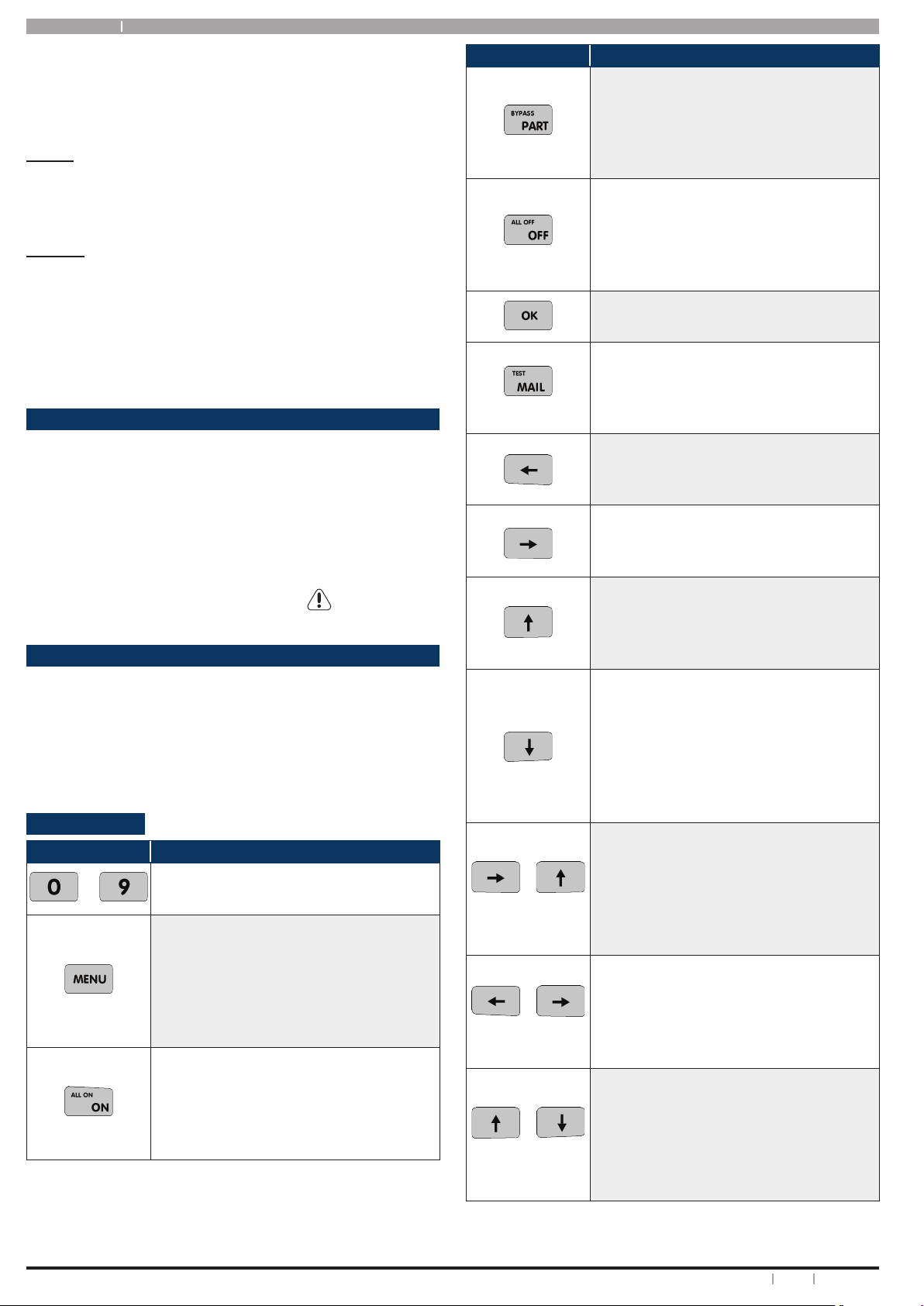
Key
Description
The [PART] key allows you to turn an
area Part On. This key can also be used
to bypass a zone or multiple zones
when you press and hold for two
seconds.
The [OFF] key allows you to turn an
area or output o. If your system has
been partitioned press and hold the
[OFF] key for two seconds to disarm to
disarm all areas.
The [OK] key allows you to save any
changes and exit the command.
The [MAIL] key allows you to read
stored mail. This key can also be used
to initiate a dialler test when you press
and hold for two seconds.
Your system may be programmed to send reports to your
security company. Once the report is complete, the system
returns the telephone to normal operation (check with
your security company).
Your system makes repeated attempts to send reports to
your security company. If your system fails to report, the
keypad will display the ‘service’ symbol.
About the Keypad
Your keypad has 20 keys or buttons. The buttons allow you
to input instructions and navigate the menu screens as
required. Some buttons have a secondary function which
is activated by holding them down for two seconds.
Each button’s function is described below:
Keypad Keys
Key
to
The numeric keys allow you to enter
you numbers when required.
Use the [MENU] and the numeric keys
to enter commands. The [MENU] key
is also used to go back one level when
navigating through menus or to exit a
programming location without saving
changes.
The [ON] key allows you to turn an area
or output on. If your system has been
partitioned press and hold the [ON]
key for two seconds to turn all areas on
at the same time.
Description
+
for 2 sec
+
for 2 sec
+
for 2 sec
The [] key allows you to move the
cursor left when programming text or
telephone numbers.
The [] key allows you to move the
cursor right when programming text
or telephone numbers.
The [] key allows you to navigate
through menus or to toggle characters
when programming telephone
numbers etc.
The [] key allows you to navigate
through menus or to toggle characters
when programming telephone
numbers etc. Pressing The [] key will
display current trouble conditions
when the area that the keypad is
displaying is disarmed.
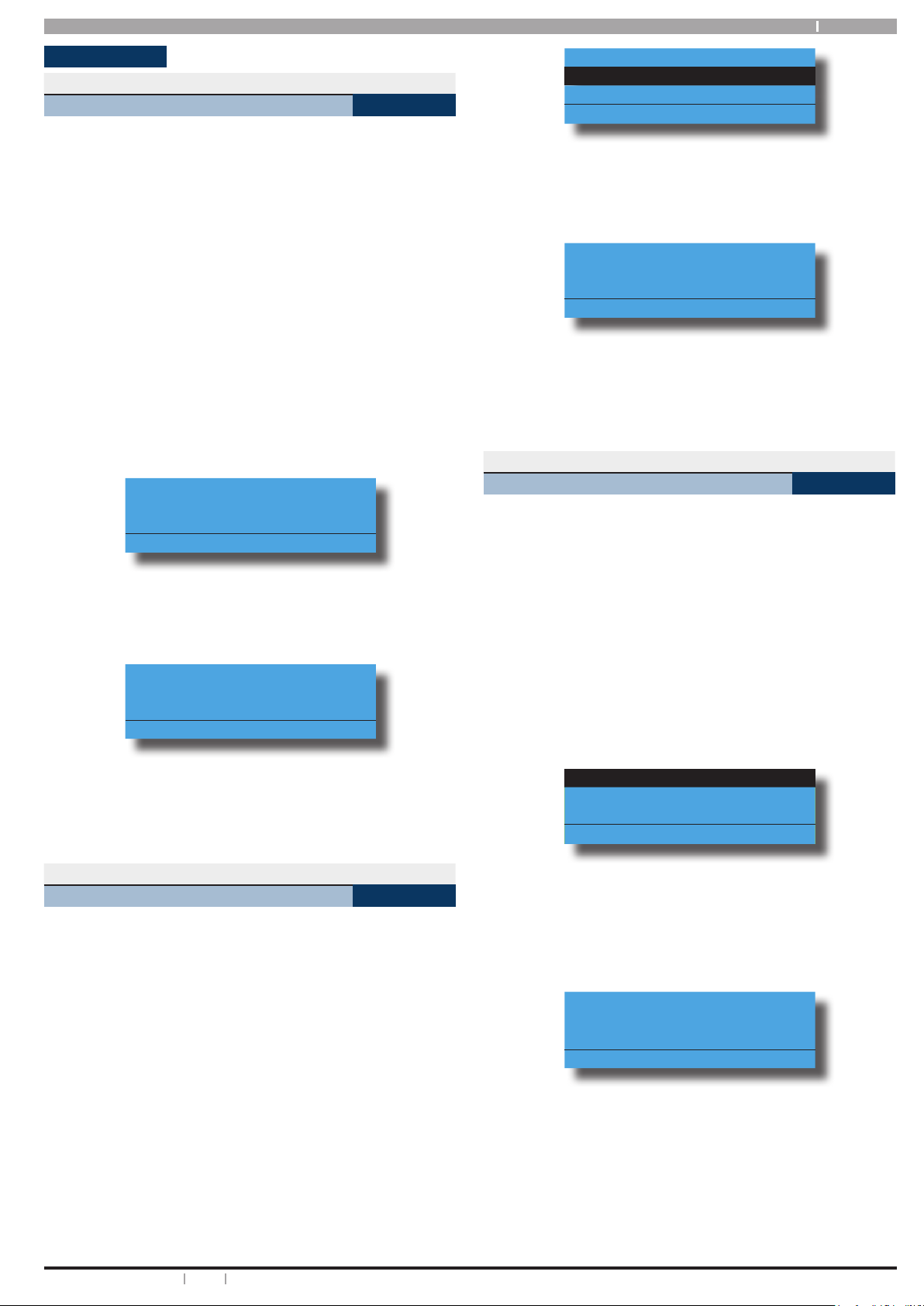
Pressing the [] and [] keys together
and holding them down for 2 seconds
will cause a Panic alarm to be triggered.
If programmed the sirens will sound
and the monitoring station will be
notied.
Pressing the [] and [] keys together
and holding them down for 2 seconds
will cause a Fire alarm to be triggered. If
programmed the sirens will sound and
the monitoring station will be notied.
Pressing the [] and [] keys together
and holding them down for 2 seconds
will cause a Medical alarm to be
triggered. If programmed the sirens
will sound and the monitoring station
will be notied.
Table 2: Keypad Keys and Their Function
6 Bosch Security Systems 04/12 BLCC600U
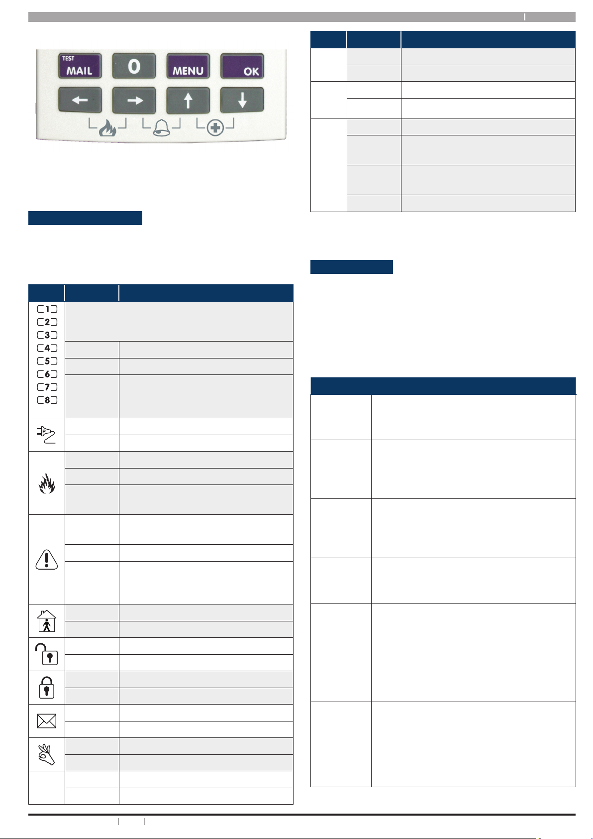
Figure 1: Keypad Emergency Alarm Triggers
Status Icons / LED’s
The following table describes the function of each of
the status icons and indicator lights. Some keypads and
readers also include a blue indicator which is used when
controlling doors or user access.
Icon Status Meaning
The keypad can display which areas (1 – 8) are
turned on or o via the Area Icon Indicators. This
option needs to be enbled by your installer,
On The area is turned All On or Part On
O The area is turned O
Solution 144 User Guide
Icon Status Meaning
Green
LED
Red &
Green
LED
On Area is o
Flashing Area not ready to turn on
Flashing Installer programming mode is active
O User Programming Mode is Active
On Door Locked
Blue
LED
Fast
Flash
2
Flashes
Door Unlocked
Door Unlocked by TimeZone
O Access Group not programmed
Table 3: Status ICONs, LED Indicator’s and Their Meanings
Keypad Tones
Your keypad emits several distinct tones and displays text
to alert you to system events. Additional bells or sirens
may also be connected to your system. Bells or sirens
mounted on the exterior of your premises alert neighbours
to emergencies and provide an audible guide for police
and re ghters.
Red
LED
Flashing
Fast
The area has an alarm
On System power is normal
Flashing System power is missing
Flashing A re alarm is active
O No re alarm
On
On
Fire alarm in memory (Turn the area
All On and O to clear).
The existing service or trouble
condition has been acknowledged
O No service or trouble conditions exist
A service or trouble condition is
Flashing
present that has not been acknowledged
On The area is turned Part On
O The area is not turned Part On
On The area is turned o.
O The area is turned All On or Part On
On The area is turned All On
O The area is turned O
On You have mail waiting to be read
O No Mail
On Area is ready to turn All On /Part On
O Not ready, Zone Open
On All On
Flashing Alarm
Type
Fire
Alarm
Tone
Burglary
Alarm
Tone
Trouble
Tone
Key
Press
Tone
Entry
Delay
Tone
Exit
Delay
Tone
Meaning
When a re zone sounds an alarm, the
keypad will sound 3 seconds on and 2
seconds o (repeat).
When a burglary zone activates while your
system is turned on, your keypad emits a
continuous siren tone. It sounds for the
time set by your security company.
When a system component is not
functioning properly, your keypad sounds
4 fast short beeps followed by a 5 second
pause (repeat).
Pressing any key on the keypad sounds one
short beep, indicating that the key press is
accepted.
When you enter the premises through
a zone programmed for entry delay, the
keypad sound a Hi/Low tone to remind you
to turn o the area. If the area is not turned
o before the entry delay expires, an alarm
condition will sound and a report may be
sent to your alarm company.
After you turn an area All On, the keypad will
sound 1 short beep every second. During
the last 10 seconds fast short beeps will be
heard. If you don’t exit before the delay time
expires and an exit delay door is faulted, an
alarm occurs.
7Bosch Security Systems 04/12 BLCC600U
Solution 144
User Guide
Error
Tone
If you press an incorrect key, your keypad
will sound a 2 second tone.
The keypad will sound a Hi / Lo tone to
Menu
Mode
indicate you have entered MENU Mode and
a Lo/Hi tone to indicate you have exited
MENU mode.
Chime
Tone
The keypad sounds fast short beeps to alert
you when a zone programmed for chime is
faulted or unsealled.
Table 4: Keypad Tones and Their Meanings
Turning An Area Part On / Part 2 On
Use this function to turn an area Part On or Part 2 On. The
control panel is factory default only for one area. Part On
and Part 2 On turns on only part of the area, leaving the
rest of the area turned o.
Only the security company can program which zones are
monitored for Part On. A master user can program which
zones are monitored when a user turns an area Part 2 On.
Once you have turned an area Part On or Part 2 On, exit
delay time starts to count down. You should leave all zones
that are active before exit delay time expires. Leaving
active zones after exit delay expires causes an alarm event.
Use Part On or Part 2 On only when you want part of an
area turned on.
1. Make sure that all zones are normal (not faulted).
2. Enter your PIN, then press the [PART] key.
If your PIN is valid and if all zones are normal, the
keypad will prompt you to select Part On or Part 2 On.
Figure 2: CP700B Graphic Keypad
Basic System Operation
Turning An Area All On
Use this function to turn an area All On. The control panel
is factory defaulted for one area. As soon as you turn an
area on, exit time will start. Exit time allows you to exit
the premises without sounding an alarm. Your security
company programs the length of exit delay time.
1. Make sure that all zones are normal (not faulted).
3. Using the arrow keys, highlight Part On or Part 2 On
then press [OK].
Exit delay time will start. You should leave now. If
your system has a faulted zone, you should return it to
normal, or bypass the faulted zone.
During exit delay, you may stop the system from
turning Part On by entering your PIN followed by the
[OFF] key.
4. When exit time has expired, the keypad will display
the Part On icon.
5. To turn the system o, enter your PIN, then press
[OFF].
Turning The System Off
When the system is on, you must enter through a designated
entry door to prevent an alarm. Opening a designated door
(e.g. front door) will start entry time. During entry time,
the keypad will emit a pulsing tone “beep” to remind you to
turn the system o. To turn o, enter your PIN followed by
the [OFF] key before the entry delay time expires.
2. Enter your PIN, then press the [ON] key.
If your PIN is valid and if all zones are normal, exit delay
time will start. You should leave now. If your control
panel detects a faulted zone, you should return it to
normal, or bypass the zone.
During exit delay, you may stop the area from turning
If you enter through the wrong door or fail to turn the
system o before the entry delay time expires, you may
cause a false alarm. If this situation arrises, silence the
alarm by entering your PIN followed by the [OFF] key and
call your security company to let them know that it is not
an emergency situation.
on by entering your PIN followed by the [OFF] key.
3. To turn the system (or area) o, enter your PIN, then
press [OFF].
1. Enter your PIN + [OFF] to turn the system (or area)
o. The keypad will no longer display the ‘Lock’ or
‘Part’ icons.
8 Bosch Security Systems 04/12 BLCC600U

Solution 144 User Guide
Silencing Alarms
When the control panel has registered an alarm, the keypad
(s) and sirens will sound to alert personnel that an alarm
occurred. The keypad will scroll in the display all alarms on
the keypad display for visual feedback. If you enter your
PIN before the system dials your security company, the
alarm report is cancelled (if programmed).
1. Enter your PIN + [OFF] to silence any alarm and turn
the system o.
The keypad will continue to scroll all alarm events that
caused the alarm. This is called alarm memory.
2. To clear alarm memory, turn the area on and o
again (eg. PIN + [ON] + PIN + [OFF]).
Automatic Arming
Your system may have been programmed to automatically
arm itself at a certain time of the day.
If for some reason you are still in the building when the
auto arming is taking place then it is possible to extend
or delay the auto-on time (automatic arming time) by one
hour simply by entering your PIN during the auto-on prealert time. The auto-on pre-alert time sounds the keypad
buzzer to warn you that the system will automatically turn
All On, Part On or Part 2 On.
Example:
If the control panel is programmed to automatically turn
All On at 6:00pm and the auto-on pre-alert time starts
beeping the keypad at 5:55pm, entering your PIN between
5:55pm and 6:00pm will delay the auto-on time by one
hour and the auto-on pre-alert time will again commence
at 6:55pm. Therefore the system will automatically turn All
On at 7:00pm.
Remote Arming - Quick Arm
If you forget to arm your system it may be possible for
you to remotely arm it using a touch tone telephone if the
remote arm option has been enabled by your installer.
To arm the system call the number which the panel is
connected to and when the panel answer you will here
3 beeps in accending frequency if the panel is in the
disarmed condition. Press [0] + [#] to arm. You will hear 3
beeps in decending order when the panel arms.
All areas on the system will be armed regardless of there
condition when using the DTMF quick arm function.
DTMF Control Functions
Your system includes comprehensive DTMF control
of individual areas and outputs with full user PIN and
timezone access verication. Some features like DTMF
disarming and output control need to be enabled by your
installer.
How to Use DTMF Control
1. Once the panel answers the incoming call, the panel
will play a short welcome jingle. You now have
approximately 5 seconds to enter a valid PIN and log
onto the panel.
2. Enter PIN followed by the [#] key on your phone. If
the PIN is valid the system will respond with two
short beeps. If the PIN is invalid then a single long
beep will be heard.
If a valid PIN is not entered in time, the panel will attempt
to establish a modem connection as if connecting to
the Solution Link software.
If this happens you will need to hang up for
approximately 60 seconds before trying again.
3. Once validated, the following commands can be
performed.
If no keys are pressed for 20 seconds or the user presses
[#] [#], the control panel will play the exit jingle and
terminate the session.
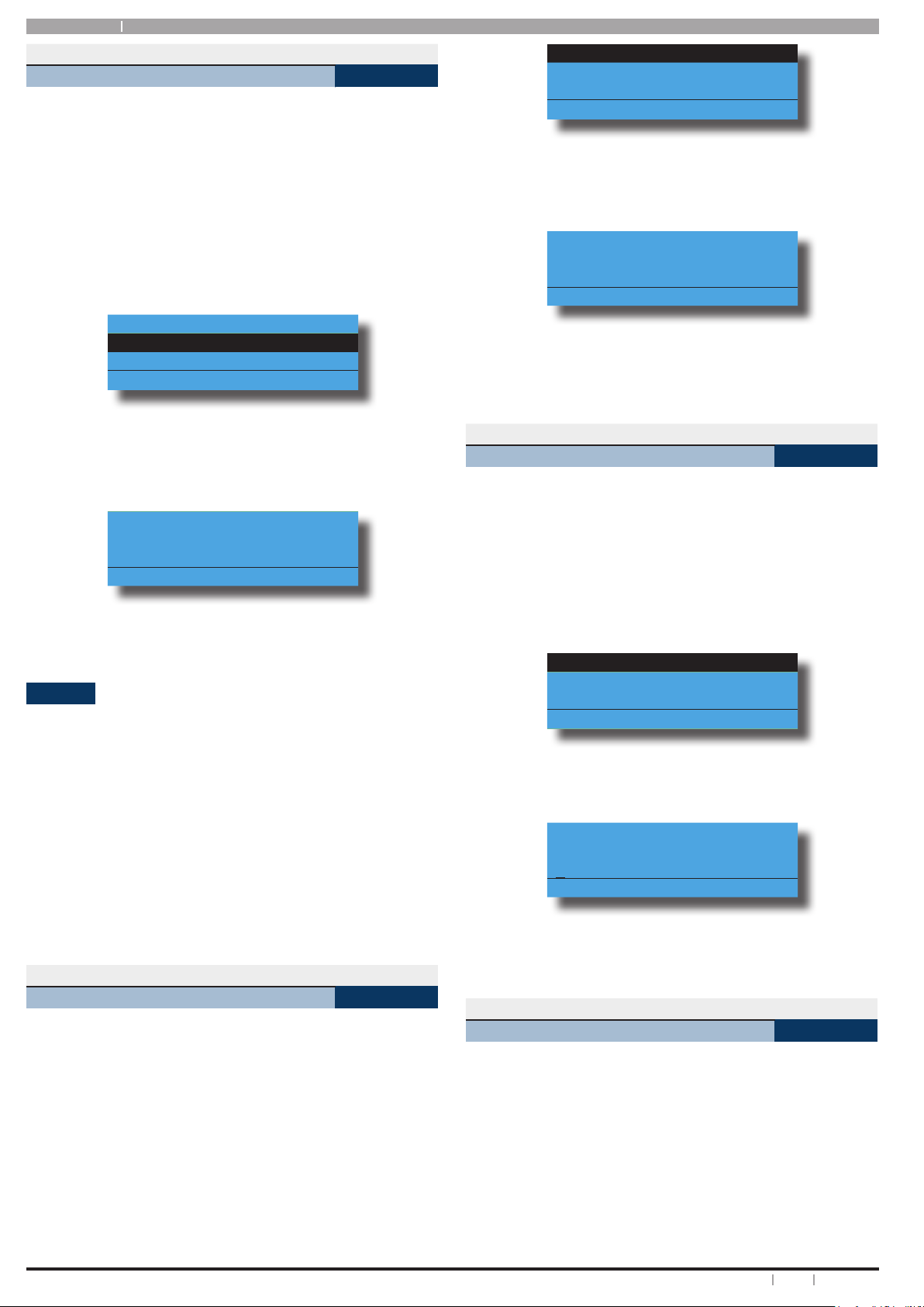
DTMF CONTROL FUNCTIONS
Operation Command Response
Quick Arm
All Areas
Log In
OK
Log In
Failed
Turn Area
All On
Turn Area
O
Turn
Output On
Turn
Output O
End
Session
[1] + [Area Nº] + [1] + [#]
[1] + [Area Nº] + [2] + [#]
[2] + [Output Nº] + [1] + [#]
[2] + [Output Nº] + [2] + [#]
[0] + [#] 2 x Beeps
[PIN] + [#]
[Invalid PIN] + [#]
[#] + [#] Exit Jingle
Welcome
Jingle
Long
Beep
2 x Beeps
(Low - High)
2 x Beeps
(High - Low)
2 x Beeps
(Low - High)
2 x Beeps
(High - Low)
Table 5: DTMF Remote Control Functions
DTMF EXAMPLES
Each example below shows the log on step for clarity. In
practise is only necessary to log on once per DTMF control
session.
To log on and turn Area 1 All On, enter the following:
[2] [5] [8] [0] + [#] = Log ON
[1] + [1] + [1] + [#] = Arm Area 1
To log on and turn Output 8 on, enter the following:
[2] [5] [8] [0] + [#] = Log ON
[2] + [8] + [1] + [#] = Turn Output 8 ON
To log on and turn Output 6 o, enter the following:
[2] [5] [8] [0] + [#]
[2] + [6] + [2] + [#]
= Log ON
= Turn Output 6 OFF
9Bosch Security Systems 04/12 BLCC600U
Solution 144
i
Note
i
Note
i
Note
User Guide
If the DTMF Quick Arm option is enabled then it is possible
to remotely turn on all areas without logging onto the
panel. Simply enter [0] + [#] following the welcome jingle.
Make sure that the telephone being used to
remotely control the panel is set to transmit DTMF
tones when keys are pressed during the call. This
option is disabled by default on some telephones.
Programming Text Using The Keypad
When programming text via the keypad, various keys on
the keypad operate dierently.
A group of characters is assigned to each of the numeric
keys on the keypad. Pressing the same numeric key again
will toggle to the next character assigned to the key (eg.
Press the [2] key will display the ‘A’ character, press the [2]
key again will toggle to the ‘B’ character, press the [2] key
again will toggle to the ‘C’ character etc).
Once the correct character is display use the arrow keys to
move to the next letter of the word you are entering. The
key assignments are identical to those found on most xed
and mobile phones.
When programming text, each numeric key represents a
dierent group of characters.
Pressing the same numeric key repeatedly will step you
through the available characters assigned to the key. The
text key layout is the same as most phones. Refer to the
table below for detailed character information.
Refer to the following table for more information.
Key Characters Assigned To Each Numeric Key
1 . , ? ! - & ` 1
2 A B C a b c 2
3 D E F d e f 3
4 G H I g h i 4
5 J K L j k l 5
6 M N O m n o 6
7 P Q R S p q r s 7
8 T U V t u v 8
9 W X Y Z w x y z 9
0 SPACE 0
Scroll Up through entire character list
Scroll Down through entire character list
Move to left one character position
Move to right one character position
OFF Clear from cursor postiion to end of line
Table 6: Text Keypad Character Set
Once the desired character is displayed press the right []
arrow key to move to the next character position. To save
programming changes, press [OK], or press [MENU] to exit
without saving.
The following additional special characters are available
by scrolling using the up and down arrow keys.
+ - @ # $ “ & % * : ( ) / < > =
Duress or Silent Alarms
A Duress or Silent Panic alarm can be easily triggered via
the keypad if you are being forced to operate the system
against your will.
To trigger a duress, enter your normal user PIN followed by
the last 2 digits of your user PIN followed by the ON or OFF
key. See the following examples.
1. If your PIN is 2580, to send a duress report when the
area is o, Enter, [2] + [5] + [8] + [0] + [8] + [0] + [OK]
or [ON].
2. If your PIN is 2580, to send a duress report when
the area is on, Enter, [2] + [5] + [8] + [0] + [8] + [0] +
[OFF].
Duress alarms are triggered by entering the user PIN
followed by the last 2 digits of the user PIN followed
by the ON or OFF key.
System Programming
Some of the examples shown in the following section
assume that you are already in programming
mode. To enter programming mode simply enter
your PIN and press the MENU key on the keypad.
Access > Commands >
Erase User
This menu lets you change your own PIN. It is recommended
that you write down your old PIN and the new one before
you begin. The new PIN must have the same number of
digits as your old PIN unless your installer has enabled the
variable length PIN option. Once the change is complete
you should destroy the written copy.
At factory default, each PIN is xed to 4 digits in length.
The default PIN for User 1 (Master user) is 2580. Only the
security installer can change the PIN length.
Enter programming mode (PIN + MENU) then,
1. Ensure that the system (or area) is turned o.
2. Enter your PIN, and then press [MENU] + [1] + [1] +
[0]. The keypad will prompt you to enter a new PIN.
To erase Ur2
Debbie Smith
press OK.
Press OK or MENU
MENU 1-0-0
10 Bosch Security Systems 04/12 BLCC600U
Solution 144 User Guide
PIN Numbers
Access > PIN Codes >
Change Own PIN
This menu lets you change your own PIN. It is recommended
that you write down your old PIN and the new one before
you begin. The new PIN must have the same number of
digits as your old PIN unless your installer has enabled the
variable length PIN option. Once the change is complete
you should destroy the written copy.
At factory default, each PIN is xed to 4 digits in length.
The default PIN for User 1 (Master user) is 2580. Only the
security installer can change the PIN length.
Enter programming mode (PIN + MENU) then,
1. Ensure that the system (or area) is turned o.
2. Enter your PIN, and then press [MENU] + [1] + [1] +
[0]. The keypad will prompt you to enter a new PIN.
Enter New PIN for Ur2
Debbie Smith
Press OK or MENU
3. Enter your new PIN, and then press [OK]. If an error
tone sounds, try a dierent PIN. The keypad will
now prompt you to enter your new PIN again.
Conrm New PIN for Ur2
Debbie Smith
Press OK or MENU
MENU 1-1-0
Ur1 John Smith
Ur2 Debbie Smith
Ur3 User 3 Name
Press
OK or MENU
2. Use the [] and [] keys to select the user that you
want to change the PIN, then press [OK] to select.
Alternatively, you can enter the user number you
want to change, then press [OK ].
Please Enter PIN for Ur2
Debbie Smith
Press OK or MENU
3. Enter the new PIN.
If an error tone sounds, try a dierent PIN.
4. Press [OK] to save and exit, or press [MENU] to exit
without saving.
Access > PIN Codes >
Add PIN
MENU 1-1-2
This menu allows a Master user to add a PIN to a new user.
A Master user can only program a new PIN for those users
that have been assigned to the same area(s) as the Master
user.
At factory default, each PIN is xed to 4 digits in length.
The default PIN for User 1 (Master user) is 2580.
Enter programming mode (PIN + MENU) then,
1. Enter [MENU] + [1] + [1] + [2].
A list of users will display on the keypad.
4. Enter your new PIN again.
5. Press [OK] to save and exit, or press [MENU] to exit
without saving Your PIN has now been changed.
Access > PIN Codes >
Change Other PIN
MENU 1-1-1
If you have a master PIN, this command allows you to
change somebody else’s PIN. It is recommended that you
write down the old PIN and the new one before you begin.
Once the change is complete you should destroy the
written copy. The new PIN must have the same number of
digits as the old PIN.
At factory default, each PIN is xed to 4 digits in length.
The default PIN for User 1 (Master user) is 2580.
Enter programming mode (PIN + MENU) then,
Ensure that the system (or area) is turned o.
1. Press [MENU] + [1] + [1] + [1]. The keypad will display
a list of available users that you can change their
PIN.
Ur1 John Smith
Ur2 Debbie Smith
Ur3 User 3 Name
Press
OK or MENU
2. Use the [] and [] keys to select the user that you
want to add a PIN, then press [OK] to select.
Alternatively, you can enter the user number you
want
to add, then press [OK].
The keypad will prompt you to enter the new pin.
Enter New PIN for Ur3
User 3 Name
Press OK or MENU
3. Enter the new PIN for the user you have selected.
If an error tone sounds, try a dierent new PIN.
4. Press [OK] to save and exit, or press [MENU] to exit
without saving.
11Bosch Security Systems 04/12 BLCC600U
Solution 144
User Guide
Access > PIN Codes >
Delete PIN
MENU 1-1-3
This menu allows a Master user the ability delete other
users PIN’s. A Master user can only delete a PIN for those
users that have been assigned to the same area(s) as the
Master user. A Master user cannot delete their own PIN.
Enter programming mode (PIN + MENU) then,
1. Make sure that the system is turned o.
2. Press [MENU] + [1] + [1] + [3].
The keypad will list all users that you can delete.
Ur1 John Smith
Ur2 Debbie Smith
Ur3 User 3 Name
Press
OK or MENU
3. Use the [] and [] keys to highlight the user whose
PIN you want to delete, then press [OK] to select.
Alternatively, you can enter the user number you
want to delete, then press [OK].
Press OK to delete PIN
For Ur2
Debbie Smith
Press OK or MENU
Ur1 John Smith
Ur2 Debbie Smith
Ur3 User 3 Name
Press
OK or MENU
3. If you are using a keypad with built in reader the
system will prompt you to present the token to the
keypad. Once the token is presented the keypad we
beep and return to the menu.
To add token for Ur1
JOHN SMITH present new
token
Press OK or MENU
A Master user can only delete a token for those users that
have been assigned to the same area(s) as the Master user.
Access > Token >
Delete Token
MENU 1-2-1
This menu allows a Master user the ability to delete a token
for those users that have been assigned to the same
area(s) as the Master user.
Enter programming mode (PIN + MENU) then,
4. Press [OK] again to delete the PIN, or press [MENU]
to cancel.
Tokens
This section outlines how to add and delete token cards
that allow an alternate method for users to turn the system
on and o via a prox reader enabled Keypads. The system
can also be congured to automaticall open a door if it has
been tted with an electric door lock. You should discuss
this feature with your installer for more details on your
particular installation.
A token is a small plastic tag card that has a unique ID. A
user can place the token card in front of a keypad that has
a built-in token reader to turn the system or specic areas
on and o.
Access > Token >
Add Token
This menu allows a Master user the ability to add a new
token for for those users that have been assigned to the
same area(s) as the Master user.
Enter programming mode (PIN + MENU) then,
1. Enter [MENU] + [1] + [2] + [0].
A list of users will display on the keypad.
MENU 1-2-0
1. Enter [MENU] + [1] + [2] + [1].
A list of users will display on the keypad.
Ur1 John Smith
Ur2 Debbie Smith
Ur3 User 3 Name
Press
OK or MENU
2. Use the [] and [] keys to select the user who’s
token you want to delete, then press [OK] to select.
To delete token for Ur1
John Smith Press OK
009553507
Press OK or MENU
3. When prompted press the [OK] key to conrm token
deletion.
Access > Token >
Token Status
MENU 1-2-2
This menu allows a Master user the ability to identify a
token which has been programmed into the system. Only
tokens that have been assigned to the same area(s) as the
Master user cn be identied.
Enter programming mode (PIN + MENU) then,
2. Use the [] and [] keys to select the user that you
want to add a token for, then press [OK] to select.
1. Enter [MENU] + [1] + [2] + [2].
The system will prompt you to present the token to
the keypad.
12 Bosch Security Systems 04/12 BLCC600U

Solution 144 User Guide
2. Once the token is presented the system will display
the owner of the token.
Token belongs to Ur2
Debbie Smith
Press OK or MENU
Access > Token >
Edit Token
MENU 1-2-3
This menu allows a Master user the ability to delete a token
for those users that have been assigned to the same
area(s) as the Master user.
Enter programming mode (PIN + MENU) then,
1. Enter [MENU] + [1] + [2] + [1].
A list of users will display on the keypad.
2. Use the [] and [] keys to select the user who’s
token you want to delete, then press [OK] to select.
ID number:
Enter Keyfob ID Ur16
User 16 Name
000000000
Press OK or MENU
3. Enter the RF Keyfob ID Number
4. Press [OK] to save and exit, or press [MENU] to exit
without saving.
Access > RF Keyfob >
Delete Keyfob
MENU 1-3-1
This menu allows the security installer or a master user to
delete the RF keyfob ID that has been assigned to a user.
Enter programming mode (PIN + MENU) then,
1. Enter [MENU] + [1] + [3] + [1].
A list of users will display on the keypad.
Edit Token Ur2
Debbie Smith
000000000
Press 0-9 OK to SAVE
3. When prompted press the [OK] key to conrm token
deletion.
RF Keyfob
This section outlines how to add and delete RF keyfobs
which provide an alternate method for users to turn an
area(s) on and o. The RF Keyfob must be compatible with
the RF Receiver that has been installed by the security
company.
Access > RF Keyfob >
Add Keyfob
This menu allows the security installer or a master user to
program the user’s keyfob ID number.
Enter programming mode (PIN + MENU) then,
1. Enter [MENU] + [1] + [3] + [0].
MENU 1-3-0
Ur1 John Smith
Ur2 Debbie Smith
Ur3 User 3 Name
Press
OK or MENU
2. Use the [] and [] keys to select the user that you
want to delete the keyfob, then press [OK] to select.
Alternatively, you can enter the user number, then
press [OK].
Delete Keyfob ID Ur2
Debbie Smith
009553507
Press OK or MENU
3. Press [OK] to delete the RF Keyfob ID number and
exit, or press [MENU] to exit without saving.
Access > User Properties >
User Name
MENU 1-4-0
This menu allows the master user to program the user’s
name. A maximum of 16 characters can be entered.
Enter programming mode (PIN + MENU) then,
A list of users will display on the keypad.
Ur1 John Smith
Ur2 Debbie Smith
Ur3 User 3 Name
Press
OK or MENU
2. Use the [] and [] keys to select the user that you
want to add the RF keyfob ID, then press [OK] to
select. Alternatively, you can enter the user number
you, then press [OK].
The keypad will prompt you to enter the RF keyfob
1. Enter [MENU] + [1] + [4] + [0].
A list of users will display on the keypad.
Ur1 John Smith
Ur2 Debbie Smith
Ur3 User 3 Name
Press
OK or MENU
2. To program the user name, use the [] and [] keys
to select the user that you want to program, then
press [OK] to select. Alternatively, you can enter the
user number you want to program, then press [OK].
13Bosch Security Systems 04/12 BLCC600U
Solution 144
User Guide
The keypad will display the current user name.
User Name Ur1
Follow the procedure below to congure the required
options.
1. Enter your Master PIN + [MENU].
User 1 Name
Press
OK to SAVE
3. Use the [] and [] keys to scroll the cursor left
and right across the user name text. Use the [] and
[] keys to scroll through the dierent characters
available. To clear all text from the cursor position,
press the [OFF] key.
4. When the user name is complete, press [OK] to save
and exit, or press [MENU] to exit without saving.
Access > User Properties >
Area Assignment
MENU 1-4-1
This menu allows the master user to program which areas
(1 to 4) a user can access. Each user can be assigned to
one or multiple areas. The master user is restricted and can
only assign another user to any one or multiple areas that
the master user has been assigned to. At factory default,
each user is assigned to operate Area 1.
Enter programming mode (PIN + MENU) then,
1. Enter [MENU] + [1] + [4] + [1].
A list of users will display on the keypad.
2. To assign areas to a user, use the [] and [] keys to
select the user that you want to program, then press
[OK] to select. Alternatively, you can enter the user
number you want to program, then press [OK].
The keypad will display which areas the user has
been assigned to.
Security System
Area 2 Name
Area 3 name
Press
OK ON OFF MENU
3. Use the [] and [] keys to select the area that
you want to assign to the user. Press the [ON] key
to assign the user to the area (√ will display) or
press the [OFF] key to disable the user from the
corresponding area (√ will no longer display).
4. Repeat Step 3 until you have assigned the user to all
areas that are required.
2. Enter [1] + [4] + [2] + [OK].
The keypad will display the list of current options.
Options with a preceeding tick mark are selected.
Master User
Reserved
Arm Only
Press
OK ON OFF MENU
3. Use the [] and [] keys to highlight the feature that
you want to program, then use the [ON] and [OFF]
keys to turn on and o the features as required.
4. When all user options are programmed, press [OK] to
save and exit, or press [MENU] to exit without saving.
TimeZones
Timezones can be used to restrict users from operating
doors or from controlling the alarm system outside given
times of the day, days of the week or during holidays.
A master code holder is able to change the timezone
parameters so they can control the access times for a given
user. If a resticted user tries to operate the system outside
their assigned timezone then access will be denied.
See MENU 7-5-0 for more information on timezone
programming.
Access > User Properties >
TimeZone Access
This menu is used to assign a user to a timezone. Timezones
can be used to restrict a users access to be within specic
times of the day and or days of the week. Each User can
only be assigned to one timezone. Setting this option to
timezone 1 will give the user 24 hour access to the system.
Enter programming mode (PIN + MENU) then,
1. Enter [MENU] + [1] + [4] + [4] and select the user
from the list then press [OK].
Ur1 John Smith
Ur2 Debbie Smith
Ur3 User 3 Name
Press
OK or MENU
MENU 1-4-4
5. Press [OK] to save and exit, or press [MENU] to exit
without saving.
Access > User Properties >
User Options
MENU 1-4-2
This menu allows the master user to set or change various
options for other users on the system. You should discuss
these options with your installer before making changes.
14 Bosch Security Systems 04/12 BLCC600U
2. Using the numeric keys, enter the timezone.
Valid entries are 1 – 16 or 0 to disable.
TimeZone Access Ur1
01 - 24 Hour TimeZone
Press
0-9 OK to SAVE
3. Press [OK] to save and exit or press [MENU] to exit
without saving.
 Loading...