

Page 1
System Checkout | 17SM CS Series Heat
SYSTEM CHECKOUT
After completing the installation, and before
energizing the unit, the following system checks
should be made:
1. Verify that the supply voltage to the heat pump
is in accordance with the nameplate ratings.
2. Make sure that all electrical connections are
tight and secure.
3. Check the electrical fusing and wiring for the
correct size.
Ensure cabinet and Electrical Box are
properly grounded.
4. Verify that the low voltage wiring between the
thermostat and the unit is correct.
5. Verify that the water piping is complete and
correct.
6. Check that the water flow is correct, and
adjust if necessary.
7. Check the blower for free rotation, and that it
is secured to the shaft.
8. Verify that vibration isolation has been
provided.
9. Unit is serviceable. Be certain that all access
panels are secured in place.
Considerations:
• Always check incoming line voltage power
supply and secondary control voltage for
adequacy. Transformer primaries are dual
tapped for 208 and 230 volts. Connect the
appropriate tap to ensure a minimum of 18
volts secondary control voltage. 24 volts is
ideal for best operation.
•Long length thermostat and control wiring
leads may create voltage drop. Increase wire
gauge or up-size transformers may be required
to insure minimum secondary voltage supply.
• FHP recommends the following guidelines for
wiring between a thermostat and the unit: 18
GA up to 60 foot, 16 GA up to 100 ft and 14 GA
up to 140 ft.
• Do not apply additional controlled devices to
the control circuit power supply without
consulting the factory. Doing so may void
equipment warranties.
• Check with all code authorities on
requirements involving condensate disposal/
over flow protection criteria.
UNIT START-UP
1. Set the thermostat to the highest setting.
2. Set the thermostat system switch to “COOL”,
and the fan switch to the “AUTO” position. The
reversing valve solenoid should energize. The
compressor and fan should not run.
3. Reduce the thermostat setting approximately 5
degrees below the room temperature.
4. Verify the heat pump is operating in the cooling
mode.
5. Turn the thermostat system switch to the
“OFF” position. The unit should stop running
and the reversing valve should de energize.
6. Leave the unit off for approximately (5)
minutes to allow for system equalization.
7. Turn the thermostat to the lowest setting.
8. Set the thermostat switch to “HEAT”.
9. Increase the thermostat setting approximately
5 degrees above the room temperature.
10. Verify the heat pump is operating in the heating
mode.
11. Set the thermostat to maintain the desired
space temperature.
12. Check for vibrations, leaks, etc.
MAINTENANCE
1. Filter changes or cleanings are required at
regular intervals. The time period between
filter changes will depend upon type of
environment the equipment is used in. In a
single family home, that is not under
construction, changing or cleaning the filter
every 60 days is sufficient. In other
applications such as motels, where daily
vacuuming produces a large amount of lint,
filter changes may need to be as frequent as
biweekly.
Equipment should never be used during
construction due to likelihood of wall board
dust accumulation in the air coil of the
equipment which permanently affects the
performance and may shorten the life of the
equipment.
8 733 920 846 (2015/01)Revised 01-15
Page 2
18 | Maintenance SM CS Series Heat Pump
2. An annual “checkup” is recommended by a
licensed refrigeration mechanic. Recording the
performance measurements of volts, amps,
and water temperature differences (both
heating and cooling) is recommended. This
data should be compared to the information on
the unit’s data plate and the data taken at the
3. Lubrication of the blower motor is not
required, however may be performed on some
motors to extend motor life. Use SAE-20 nondetergent electric motor oil.
4. The condensate drain should be checked
annually by cleaning and flushing to insure
proper drainage.
original startup of the equipment.
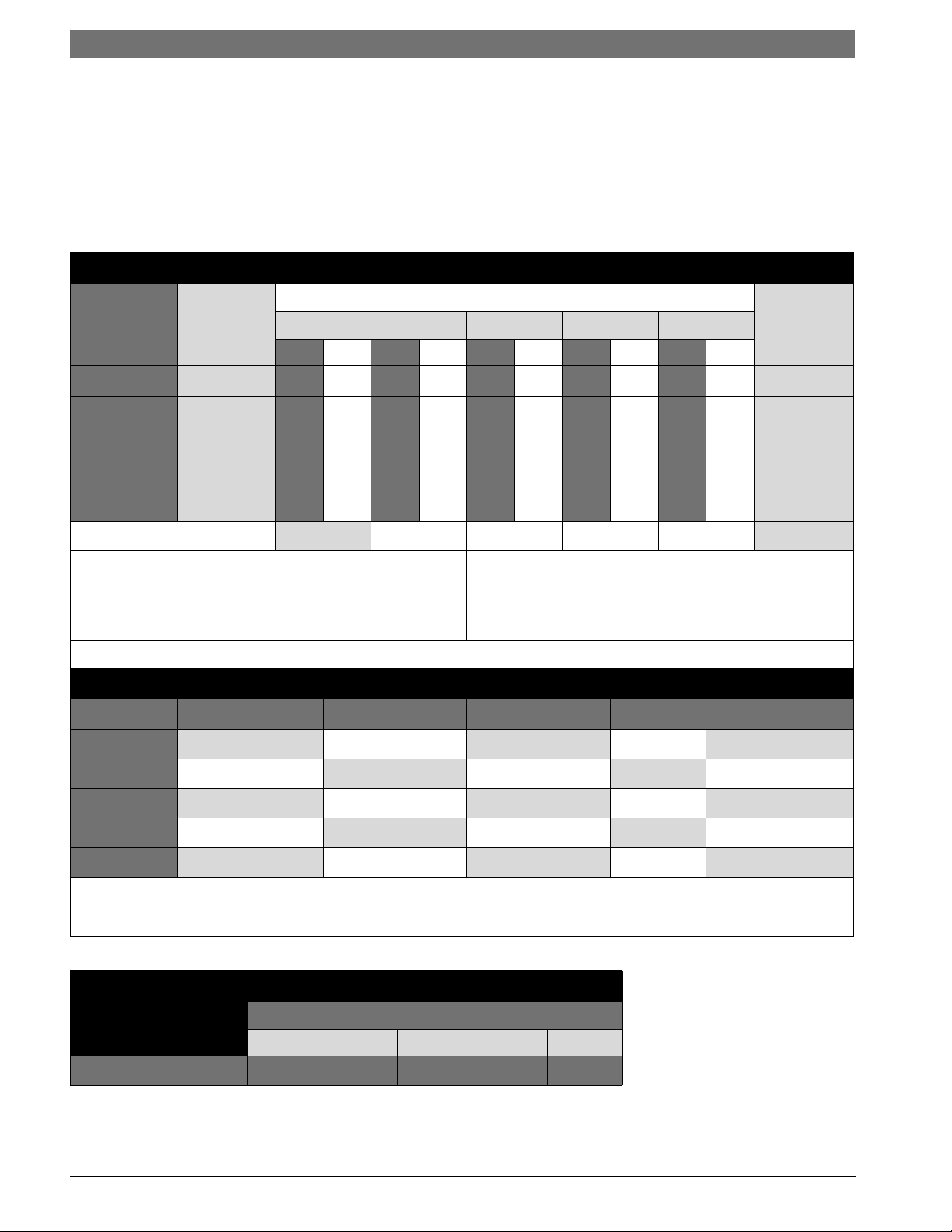
Figure 12: Refrigerant Charge, Line Sizing and Capacity Multiplier Chart
SYSTEM
MODEL
Factory
R410A
Charge
SM024
SM036
SM048
SM060
SM070
CAPACITY MULTIPLIER
(Oz)*
80
86
93
115
127
Refrigerant Line O.D. Size (Based on Equivalent Line Length)
25 FT. 35 FT. 45 FT. 50 FT. 75 FT
LIQ. SUC. LIQ. SUC. LIQ. SUC. LIQ. SUC. LIQ. SUC.
3/8 3/4 3/8 3/4 3/8 3/4 3/8 3/4 3/8 7/8
3/8 3/4 3/8 3/4 3/8 3/4 3/8 7/8 3/8 7/8
3/8 7/8 3/8 7/8 3/8 7/8 3/8 7/8 3/8 7/8
3/8 1-1/8 3/8 1-1/8 3/8 1-1/8 3/8 1-1/8 3/8 1-1/8
3/8 1-1/8 3/8 1-1/8 3/8 1-1/8 3/8 1-1/8 3/8 1-1/8
1.00 .995 0.990 0.990 0.980
Suct. Line
Riser Max.
3/4
3/4
7/8
7/8
7/8
Example 1:
Model SM036 with 45ft of equivalent length of 3/8” O.D Liquid
Line. Total system charge= Factory charge + (45ft - 25 ft) x .60
oz/ft Total System Charge =86 oz + (20ft x .60 oz/ft) = 98 oz.
Additional 12 oz of R410A refrigerant required.
Note: Charge value shown for paired SM air handler.
Example 2:
Model SM060 with 10ft of equivalent length of 3/8” O.D
Liquid Line. Total system charge= Factory charge - (25ft 10ft) x .60 oz/ft Total System Charge = 115 oz - (15ft x .60 oz/
ft) = 106 oz. Removal of 9oz of R410A refrigerant required.
Charge adjustments for SM CS when paired with DX AH (oz)
Unit
SM024-1CSC
SM036-1CSC
SM048-1CSC
SM060-1CSC
SM070-1CSC
Example 3:
Model SM036 CS paired with DX049 AH with 45ft of equivalent length of 3/8” O.D Liquid Line. Total system charge = Factory
charge + (DX charge adjustments) + (45ft - 25ft) x .60 oz/ft) = 123 oz. Additional 37 oz of R410A refrigerant required.
DX025 DX035 DX049 DX061 DX071
-2 12 ---
- 025--
--22 - -
- --10 6
----0
Figure 13: Liquid Line Charge Per Linear Foot
R410A oz per foot
Liquid Line Size, O.D.
1/4 5/16 3/8 1/2 5/8
.25 .44 .60 1.15 1.95
SM CS Series Heat Pump8 733 920 846 (2015/01) Subject to change without prior notice
 Loading...