

Bosch SM024, SM060, SM070, SM036, SM048 Installation, Operation And Maintenance Manual
SM Series Heat pump
SM024 | SM036 | SM048 | SMO60 | SM070
Installation, Operation and Maintenance Manual
6 720 220 406 (2015/02)
2 |
SM Series Heat Pump
CONTENTS
Key to Symbols...................................................................3
Safety Warnings ................................................................ 3
Standard package.............................................................. 3
Model Nomenclature.......................................................... 3
General Description........................................................... 5
Moving and Storage ........................................................... 6
Initial Inspection ............................................................... 6
Location............................................................................ 6
Configurability .................................................................. 7
Horizontal Configurability .................................................. 7
Required Tools ............................................................ 7
Instructions - Left-Hand Unit (SM0**-1HZ-*L*-**) ............... 7
Instructions - Right-Hand Unit (SM0**-1HZ-*R*-**) ........... 10
Counter-Flow configurability............................................ 13
Vertical Configurability.................................................... 13
Required Tools .......................................................... 15
Access to Internal Components.................................... 15
Blower Re-Configuration ............................................. 17
Condensate Drain Connection Re-configuration ............. 20
HRP Switch Relocation ............................................... 21
Electric Heat Relocation.............................................. 22
Electrical Box re-configuration ..................................... 24
Reinstall All Panels ..................................................... 25
Return and Discharge Duct Flanges .................................. 25
Pre Installation Unit Preparation ...................................... 26
Corner Cap Installation Instructions .............................. 26
DPS Water Flow Proving..............................................38
Pump Relay ............................................................... 38
Comfort Alert Module .................................................38
Smart Start Assist.............................................................39
Mode of Operation Notes............... ...............................40
Heat Recovery Package .................................................... 41
Water Tank Preparation ..............................................41
HR Water Piping.........................................................41
Water Tank Refill ........................................................42
Initial Start-Up ...........................................................42
Sequence of Operation.....................................................43
Cooling Mode ............................................................ 43
Heating Mode ............................................................43
Application Considerations ..............................................45
Well Water Systems.................................................... 45
Cooling Tower/Boiler Systems ..................................... 45
Geothermal Systems ..................................................47
System Checkout .............................................................48
Unit Start-up....................................................................48
Maintenance ...................................................................49
Unit Check-Out Sheet .......................................................50
Customer Data...........................................................50
Unit Nameplate Data................................................... 50
Operating Conditions..................................................50
Auxiliary Heat ............................................................50
Troubleshooting ..............................................................51
Electronic Thermostat Installation ....................................56
Operating Temperatures and Pressures ............................ 57
Airflow Tables..................................................................62
Mounting Vertical Units ................................................... 27
Mounting horizontal Units ................................................ 27
Hanging Bracket kit..........................................................27
Condensate Drain ............................................................ 28
Duct System.................................................................... 29
Piping ............................................................................. 29
Electrical ........................................................................ 30
Safety Devices and the UPM Controller ......................... 31
ECM INTERFACE BOARD ............................................ 35
Dehumidification Method Selector ............................... 36
Constant Torque Motors (ECM).................................... 36
Options........................................................................... 37
Hot Gas Reheat (HGRH).............................................. 37
Electric Heat ............................................................. 37
Heat Recovery Package (HRP) ..................................... 37
Constant Airflow Motor............................................... 38
Water Side Pressure Drop Table........................................64
Wiring Diagrams ..............................................................65
WIRING HARNESS DRAWINGS ..........................................72
Constant Torque Motor (SM0**-***-***-T*)........................72
Constant Airflow Motor (SM0**-***-***-A*) ....................... 73
Spare Parts List ...............................................................74
Dimensional Drawings......................................................95
Horizontal - Straight Through .......................................96
Horizontal - Hanging bracket location ............................97
Counter Flow.................................................. ...........98
CF Vertical ................................................................99
SM Series Heat Pump6 720 220 406 (2015/02) Subject to change without prior notice
Key to Symbols | 3SM Series Heat Pump
1
2
3
4
KEY TO SYMBOLS
Warnings
Warnings in this document are identified by
a warning triangle printed against a grey
background. Keywords at the start of the
warning indicate the type and seriousness
of the ensuing risk if measures to prevent
the risk are not taken.
The following keywords are defined and can be
used in this document:
• NOTE indicates a situation that could result in
damage to property or equipment.
• CAUTION indicates a situation that could
result in minor to medium injury.
• WARNING indicates a situation that could
result in sever injury or death.
• DANGER indicates a situation that will result in
severe injury or death.
Important Information
This symbol indicates important information
where there is no risk to property or people.
SAFETY WARNINGS
NOTE: All refrigerant discharged from this
unit must be recovered WITHOUT
EXCEPTION. Technicians must follow
industry accepted guidelines and all local,
state, and federal statutes for the recovery
and disposal of refrigerants. If a compressor
is removed from this unit, refrigerant circuit
oil will remain in the compressor. To avoid
leakage of compressor oil, refrigerant lines
of the compressor must be sealed after it is
removed.
NOTE: To avoid equipment damage, DO
NOT use these units as a source of heating
or cooling during the construction process.
Doing so may affect the unit’s warranty. The
mechanical components and filters will
quickly become clogged with construction
dirt and debris, which may cause system
damage.
STANDARD PACKAGE
WARNING: Installation and servicing of this
equipment can be hazardous due to system
pressure and electrical components. Only
trained and qualified personnel should
install, repair, or service the equipment.
WARNING: Before performing service or
maintenance operations on the system, turn
off main power to the unit. Electrical shock
could cause personal injury or death.
WARNING: When working on equipment,
always observe precautions described in
the literature, tags, and labels attached to
the unit. Follow all safety codes. Wear
safety glasses and work gloves. Use a
quenching cloth for brazing, and place a fire
extinguisher close to the work area.
NOTE: To avoid the release of refrigerant
into the atmosphere, the refrigerant circuit
of this unit must be serviced only by
technicians who meet local, state, and
federal proficiency requirements.
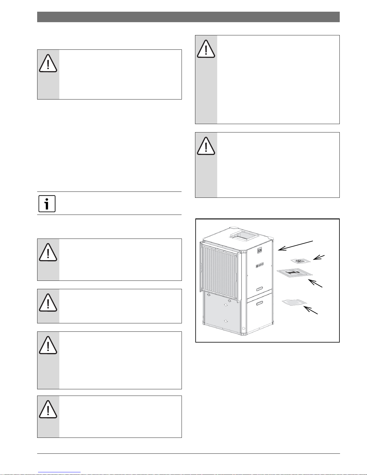
Figure # 1
[1] SM Series Water-to-Air Heat Pump
[2] Corner Caps Package
[3] Installation and Operation Manual
[4] Hanging Bracket kit (HZ unit only)
6 720 220 406 (2015/02)Revised 02-15
4 | Model Nomenclature
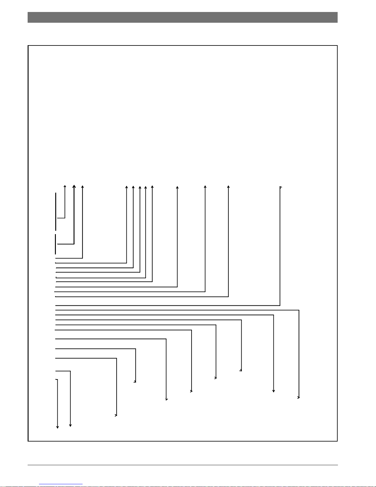
SM024 - 1 VT C - S LTATA - XXGAEXXXX7XXXX5XXXX SB A
SM
75VA Transformer +
Size
024
036 Refrigeration Circuit Options
H - Hot Gas Reheat - On/O
070 D - Heat Recovery Package
Voltage
1 208-230/60/1 General Electrical Options (up to 5 available per unit)
A - EMS relay
Cabinet Conguration E - Pump/valve relay
HZ - Horizontal H - Flow proving switch (DPS)
VT - Vertical N - Comfort Alert Module
CF - Downow (Counterow) S - Smart Start Assist
X - As default for non used electrical codes
Coax Options
N - Cupro-Nickel Application
G - EXTENDED RANGE (Geothermal)
Water Connections
y
F - Front (HZ only) Cabinet Construction
H - Painted Steel / 1/2" Closed Cell Foam
Return Air Conguration
Electric Heat (Dual power connection)
(Not Available with HGRH)
Discharge Air Conguration X - None
T - Top (VT only) A - 5 kW
E - End (HZ only) C - 10 kW
B - Bottom (CF only) D - 15 kW
E - 20 kW
Fan/Motor Options
Revision Level
T - Constant Torque ECM A - Current
Air Coil
T- Tin Plated
MERV13 - 2" w/ 4-SIDED FILTER RACK
MODEL NOMENCLATURE
SM Series Heat Pump
)
048 X - None
060
L - Left
R - Right
A - Constant Airow ECM
SM Series Heat Pump6 720 220 406 (2015/02) Subject to change without prior notice
C - Copper
Figure # 2
S - Side (VT and CF onl
General Description | 5SM Series Heat Pump
1
2
3
4
5
6
7
9
10
3
8
10
GENERAL DESCRIPTION
SM Series Water-to-Air Heat Pumps provide the
best combination of performance and efficiency
available. All units are performance certified to
American Heating and Refrigeration Institute
(AHRI) ISO Standard 13256-1. All SM Water-to-Air
Heat Pumps conform to UL1995 standard and are
certified to CAN/CSA C22.2 No 236 by IntertekETL. The Water-to-Air Heat Pumps are designed to
operate with entering fluid temperature between
20°F to 90°F in the heating mode and between
30°F to 120°F in the cooling mode
NOTE: Heat Pump operating under extreme
conditions will have limitation on air/fluid flow
rates and/or temperatures.
.
NOTE: 50° F Minimum Entering Water
Temperature (EWT) is recommended for well
water applications with sufficient water flow to
prevent freezing. Antifreeze solution is required
for all closed loop applications and EWT below
45°. Cooling Tower/Boiler and Geothermal
applications should have sufficient antifreeze
solution to protect against extreme conditions
and equipment failure. Frozen water coils are
not covered under warranty. Other equivalent
methods of temperature control are acceptable.
Safety devices are built into each unit to provide
the maximum system protection possible when
properly installed and maintained. Each unit has
externally mounted LCD error code display,
allowing unit diagnosis without opening the
cabinet.
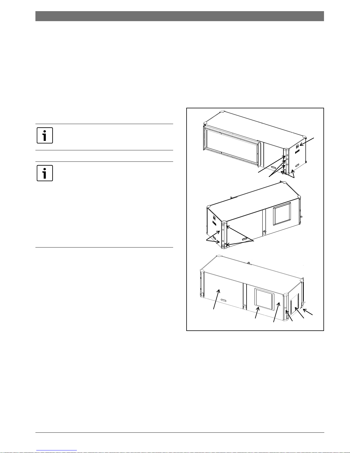
Basic Horizontal unit layout and connections are
shown in Figure #3 . Refer to Dimensional
Drawings for further detail, as well as Vertical and
Counter Flow unit details. Pg#95 through Pg#95
SM Series Water-to-Air Heat Pumps are available in
Vertical (VT), Horizontal (HZ) and Counter-Flow
(CF) configurations. VT units are field convertible
for three discharge/supply air orientations and
left-hand (LH) or right-hand (RH) return
configurations. HZ units have two field
configurable discharge/supply air orientations.
Several factory installed options are available: Hot
Gas Reheat, Electric Heat, Heat Recovery Package,
Smart Start Assist, Constant Airflow Blower Motor,
DPS Water Flow Proving Switch, Auxiliary Pump
Figure # 3
Relay, and Comfort Alert Module. Electric Heat and
Smart Start Assist are also available as field
installed accessory. See Pg#37 for more detail.
[1] LCD Error Code Display
[2] Air handler access panel
[3] Condensing section access panel
[4] Condensate drain connection
[5] Water connection
[6] Heat Recovery water connection (Optional)
[7] Heat Recovery disconnect switch (Optional)
[8] Electrical connection knockout
6 720 220 406 (2015/02)Revised 02-15
6 | Moving and Storage
[9] Electric Heat electrical connection knockout
(Optional)
[10] Blower outlet (Supply Air)
MOVING AND STORAGE
If the equipment is not needed for immediate
installation upon its arrival at the job site, it should
be left in its shipping carton and stored in a clean,
dry area. Units must only be stored or moved in the
normal upright position as indicated by the “UP”
arrows on each carton at all times.
WARNING: For storage If unit stacking is
required, stack units as follows:
Vertical units: less than 6 tons, no more
than two high.
Horizontals units: less than 6 tons, no more
than three high.
INITIAL INSPECTION
Be certain to inspect all cartons or crates on each
unit as received at the job site before signing the
freight bill. Verify that all items have been received
and that there are no visible damages; note any
shortages or damages on all copies of the freight
bill. In the event of damage or shortage, remember
that the purchaser is responsible for filing the
necessary claims with the carrier. Concealed
damages not discovered until after removing the
units from the packaging must be reported to the
carrier within 24 hours of receipt.
SM Series Heat Pump
LOCATION
Locate the unit in an indoor area that allows easy
removal of the filter and access panels, and has
enough room for service personnel to perform
maintenance or repair. Provide sufficient room to
make fluid, electrical, and duct connection(s). If
the unit is located in a confined space such as a
closet, provisions must be made for return air to
freely enter the face of unit’s air coil. On horizontal
units, allow adequate room below the unit for a
condensate drain trap and do not locate the unit
above supply piping.
NOTE: These units are not approved for
outdoor installation; therefore, they must
be installed inside the structure being
conditioned. Do not locate in areas that are
subject to freezing.
SM Series Heat Pump6 720 220 406 (2015/02) Subject to change without prior notice
Configurability | 7SM Series Heat Pump
1
1
2
2
CONFIGURABILITY
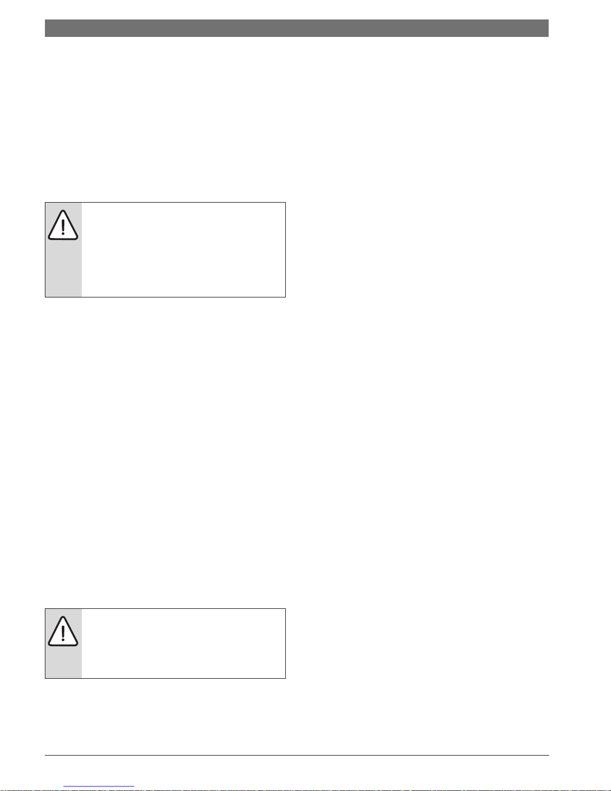
HORIZONTAL CONFIGURABILITY
The Horizontal Configuration water source heat
pump is designed to have a field configurable
blower orientation: end blow (default) and straight
through. (Figure #4 and #5)
Figure # 4
• 1/4" hex head driver
• Needle nose pliers
• 5/16”-1/4” ratchet wrench
NOTE: Discharge air configuration change is
not possible on Heat Pumps equipped with
Electric Heat Option.
Instructions - Left-Hand Unit (SM0**1HZ-*L*-**)
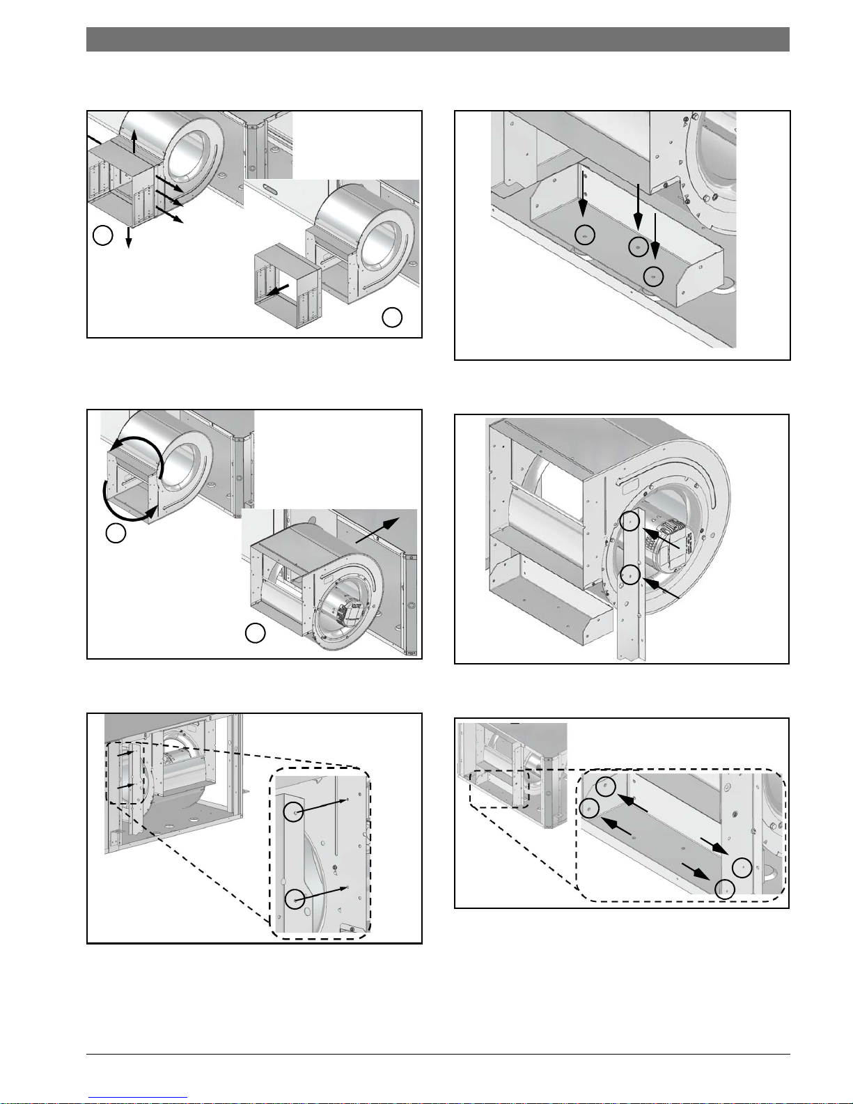
1. Remove and retain end and side panels.(Figure
#6)
Figure # 5
Left-Hand and Right-hand Horizontal (HZ) units
have different Blower Configuration instructions.
---------------------------------------------------------------
Left- Hand unit instructions refer to Pg#7 and
Right-Hand unit instructions refer to Pg#10.
Internally mounted electric heat is only available
in End Blow configuration.
Blower configuration changes should be done
prior to unit being installed in the final location.
Figure # 6
2. Disconnect blower motor wiring and ground
wire fastened to blower housing.(Figure#7)
Figure # 7
Required Tools
• 5/16" hex head driver
•3/8" hex head driver
• 7/16" hex head driver
• Flat screw driver
• Phillips screw driver
6 720 220 406 (2015/02)Revised 02-15
8 | Horizontal Configurability
SM Series Heat Pump
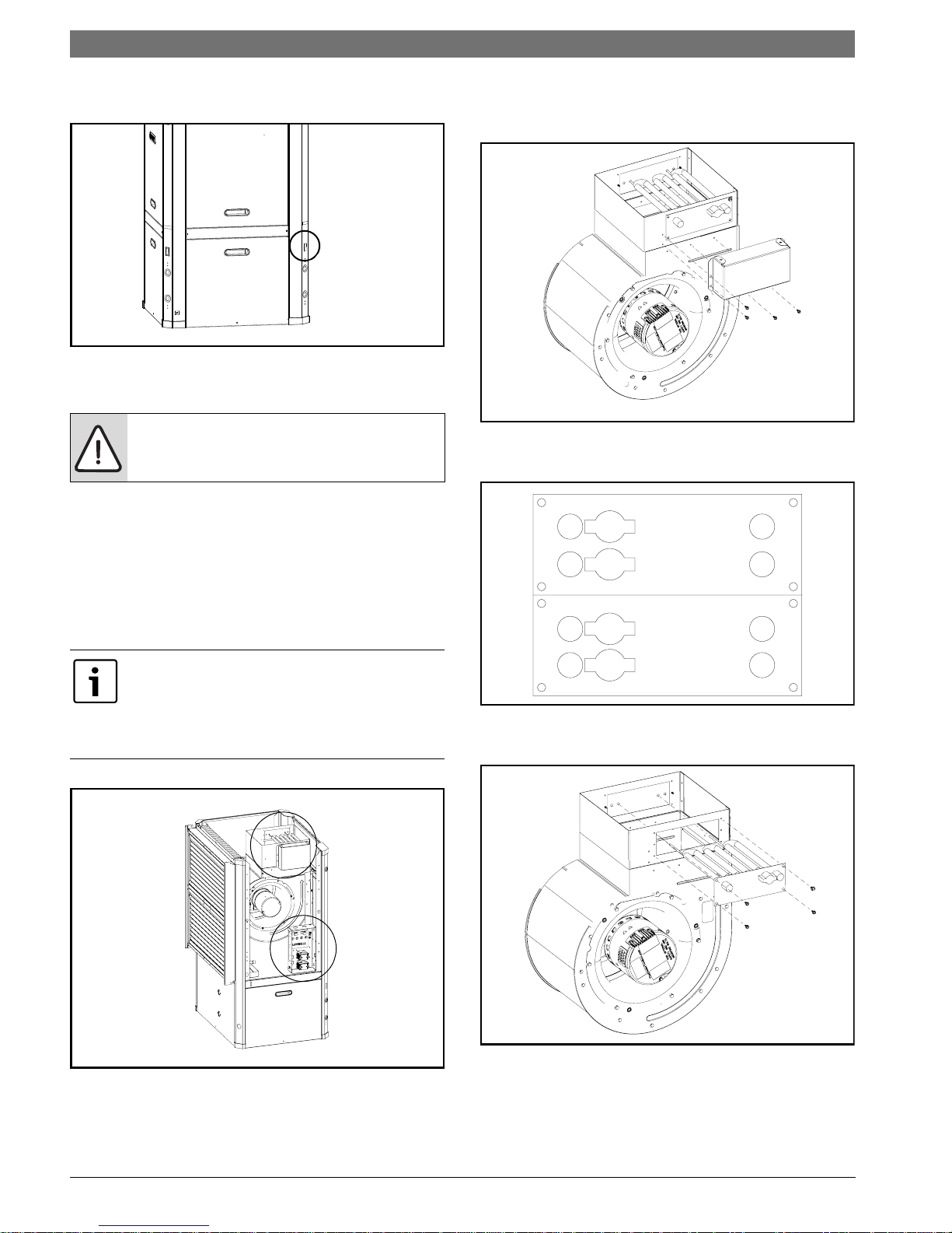
3. Remove and retain bracket by removing (3)
screws. (Figure #8)
Figure # 8
4. Loosen blower assembly by removing (4)
screws. (Figure #9)
6. Rotate the blower into its new
position.(Figure#11)
Figure # 11
7. Remove and retain remaining bracket by
removing (2) screws. (Figure #12)
Figure # 9
5. Remove and retain bracket by removing (2)
screws. (Figure #10)
Figure # 10
Figure # 12
8. Remove the blower assembly by sliding it
forward. (Figure #13)
Unit top is notched to allow blower to slide
through.
Figure # 13
SM Series Heat Pump6 720 220 406 (2015/02) Subject to change without prior notice
Horizontal Configurability | 9SM Series Heat Pump
1
2
1
2
9. Remove and discard blower collar by removing
(8) screws. (Figure #14)
Figure # 14
10. Reorient the blower assembly 180 degree with
blower “belly” down and slide back into the
cabinet. (Figure #15)
12. Reinstall bracket removed in step (#3) using
(3) screws in the same location. (Figure#17)
Figure # 17
13. Reinstall remaining bracket using (2) screws.
(Figure#18)
Figure # 15
11. Reinstall bracket in the new vertical position
using (2) screws. (Figure #16)
Figure # 16
Figure # 18
14. Connect vertical and horizontal brackets by
installing (4) screws. (Figure#19)
Figure # 19
15. Reconnect blower motor wiring and ground
wire.
6 720 220 406 (2015/02)Revised 02-15
10 | Horizontal Configurability
2
1
3
1
1
2
2
SM Series Heat Pump
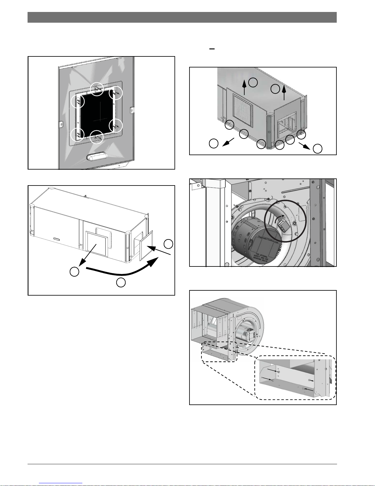
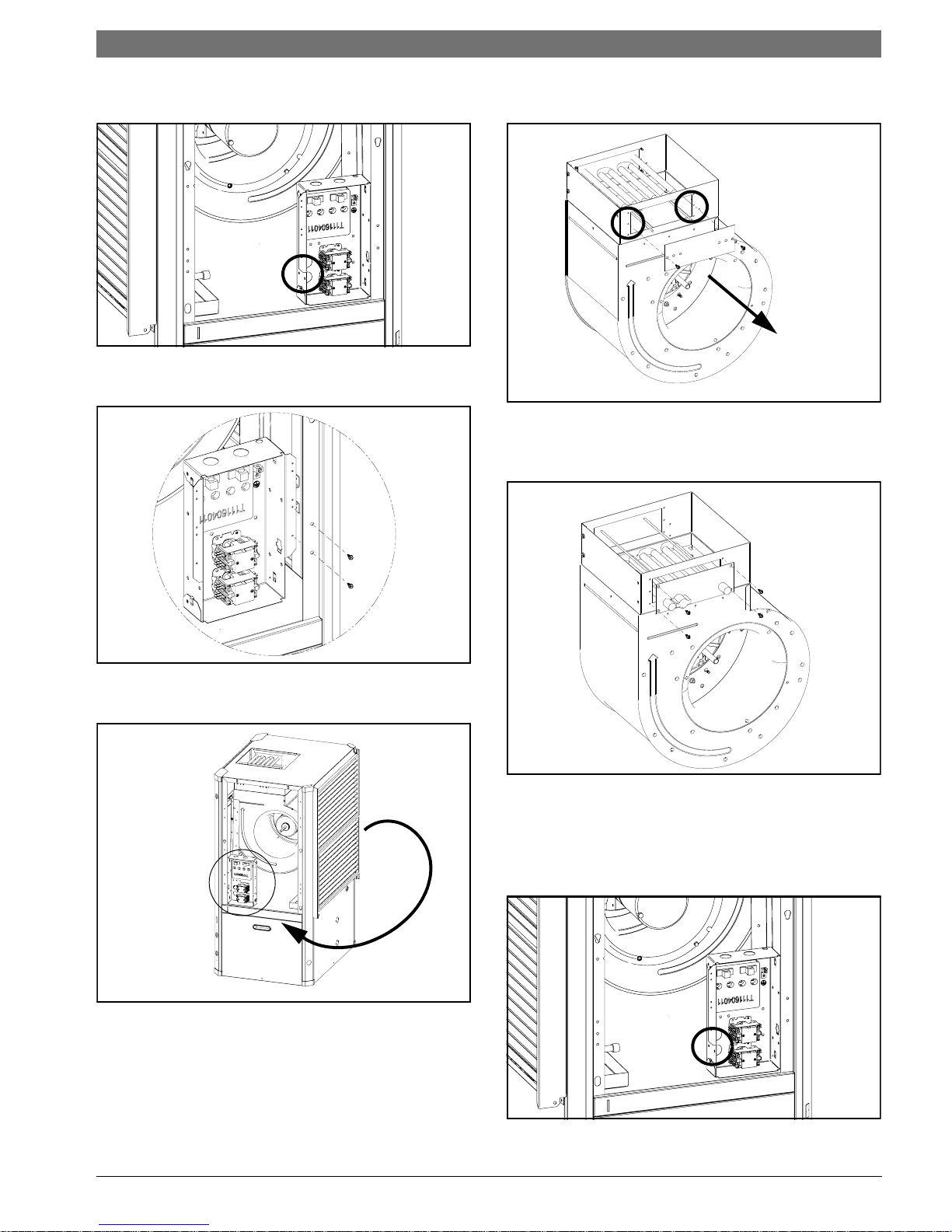
16. Remove and retain plastic Blower opening
cover by removing (6) screws and reinstall it in
the new location (Figure#20 and #21)
Figure # 20
Instructions - Right-Hand Unit (SM0**1HZ-*R*-**)
1. Remove and retain end and side
panels.(Figure#22)
Figure # 22
2. Disconnect blower motor wiring and ground
wire fastened to blower housing.(Figure#23)
Figure # 21
17. Reinstall all unit panels.
Figure # 23
3. Remove and retain (4) screws under the
blower collar. (Figure #24)
Figure # 24
SM Series Heat Pump6 720 220 406 (2015/02) Subject to change without prior notice
NOTE: Air coil is in close proximity to the
blower. Air coil fins are easily damaged.
Great care must be taken during this step to
avoid coil damage. Shipping cardboard can
be used as protection during blower
removal and installation.
4. Slide blower assembly away from mounting
bracket. (Figure #25)
Horizontal Configurability | 11SM Series Heat Pump
6. Remove and discard horizontal blower bracket
by removing (3) screws. (Figure #27)
Figure # 27
7. Rotate the blower into its new
position.(Figure#28)
Figure # 25
5. Remove and retain (1) vertical bracket by
removing (2) screws. (Figure #26)
Figure # 26
Figure # 28
8. Remove and retain remaining vertical blower
bracket by removing (2) screws. (Figure #29)
Figure # 29
6 720 220 406 (2015/02)Revised 02-15
12 | Horizontal Configurability
SM Series Heat Pump
9. Remove the blower assembly by sliding it
forward. (Figure #30)
Unit top is notched to allow blower to slide
through.
Figure # 30
10. Remove and discard blower collar by removing
(8) screws. (Figure #31)
11. Reorient the blower assembly 180 degree with
blower “belly” up. (Figure #32)
Figure # 32
12. Move the blower back into the cabinet. (Figure
#33)
Figure # 31
Figure # 33
13. Reinstall (2) vertical blower brackets in the
new horizontal position using (4) screws.
(Figure #34)
Figure # 34
SM Series Heat Pump6 720 220 406 (2015/02) Subject to change without prior notice
14. Secure (2) the now horizontal blower brackets
2
1
3
to the unit base using (4) screws. (Figure#35)
Figure # 35
15. Reconnect blower motor wiring and ground
wire.
16. Remove and retain plastic Blower opening
cover by removing (6) screws and cutting/
tearing insulation at perforations around the
perimeter of cover. Reinstall it in the new
location (Figure#36 and #37)
Counter-Flow configurability | 13SM Series Heat Pump
Figure # 37
17. Reinstall all unit panels.
COUNTER-FLOW CONFIGURABILITY
The Counter-Flow Configuration water source heat
pump is a dedicated down flow configuration.
Available from the factory in Left-hand and righthand return air configurations.
VERTICAL CONFIGURABILITY
The Vertical (VT) Configuration water source heat
pump is designed to be field configured for various
configurations. This is achieved by relocating
Electrical box (E-box), unit panels and reorienting
blower to discharge UP, BACK OR SIDE. See Figure
#37 through #41 for more detail.
The unit, as shipped from the factory, does not
have configuration on the discharge air from to
side or back, field configuration kit is requiered,
(sold as an accessory Kit).
Figure # 36
Discharge air configuration change is not
possible on Heat Pumps equipped with
Electric Heat Option.
Blower, E-box and panel configuration
changes should be done prior to unit being
installed in the final location.
6 720 220 406 (2015/02)Revised 02-15
14 | Vertical Configurability
1
2
3
Figure # 38 Top Discharge (Default)
SM Series Heat Pump
Figure # 39 Back Discharge
Figure # 40 Side Discharge
Figure # 41
[1] Logo/Front Panel
[2] Electrical Box
[3] Default Configuration (can be ordered as either
right or left hand return)
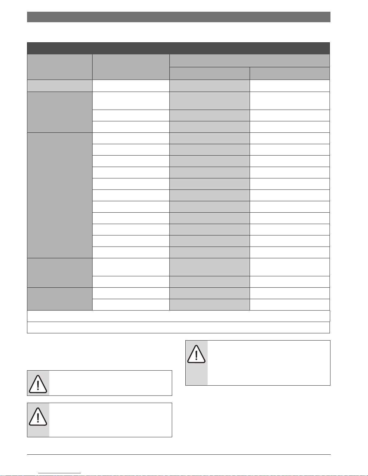
Internally mounted electric heat is only available
in Top Discharge configuration. See table below
for details
Blower Orientation and Electric Heat
Compatibility
Up Yes Internally or Duct Mounted
Back
Blower
Side
Duct Mounted
Duct Mounted
SM Series Heat Pump6 720 220 406 (2015/02) Subject to change without prior notice
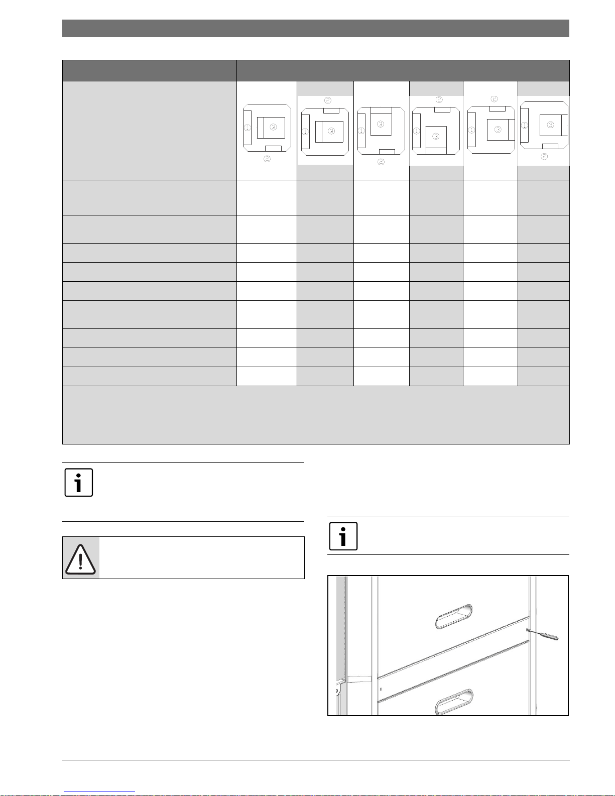
Required steps Possible unit configurations
How to use this table:
• Select desired configuration
from “possible unit
configurations”.
• Instructions with “X” have to
be performed to reconfigure
the unit.
Vertical Configurability | 15SM Series Heat Pump
ACCESS TO INTERNAL COMPONENTS
(PG#15)
BLOWER RE-CONFIGURATION (PG#17)
E-BOX CONFIGURATION (PG#24)
ELECTRIC HEAT RELOCATION* (PG#22)
CONDENSATE DRAIN RELOCATION
(PG#20)
HRP SWITCH* (PG#21)
REINSTALL PANELS (PG#25)
*APPLIES IF OPTION IS INSTALLED
[1] AIR COIL
[2] E-BOX (UNIT FRONT)
[3] BLOWER
X APPLICABLE STEP
All heat pumps are supplied with panel belt
which needs to be removed to access screws
for panel removal. The panels have additional
internal fasteners to prevent any air leakage.
For safety precautions two persons are
required to perform this operation.
Left return,
top discharge
Right return,
top
discharge
Left return,
rear
discharge
Right
return, rear
discharge
XXXXX
X XXX
X XX
X*
X XX
X* X* X* X*
XXXXX
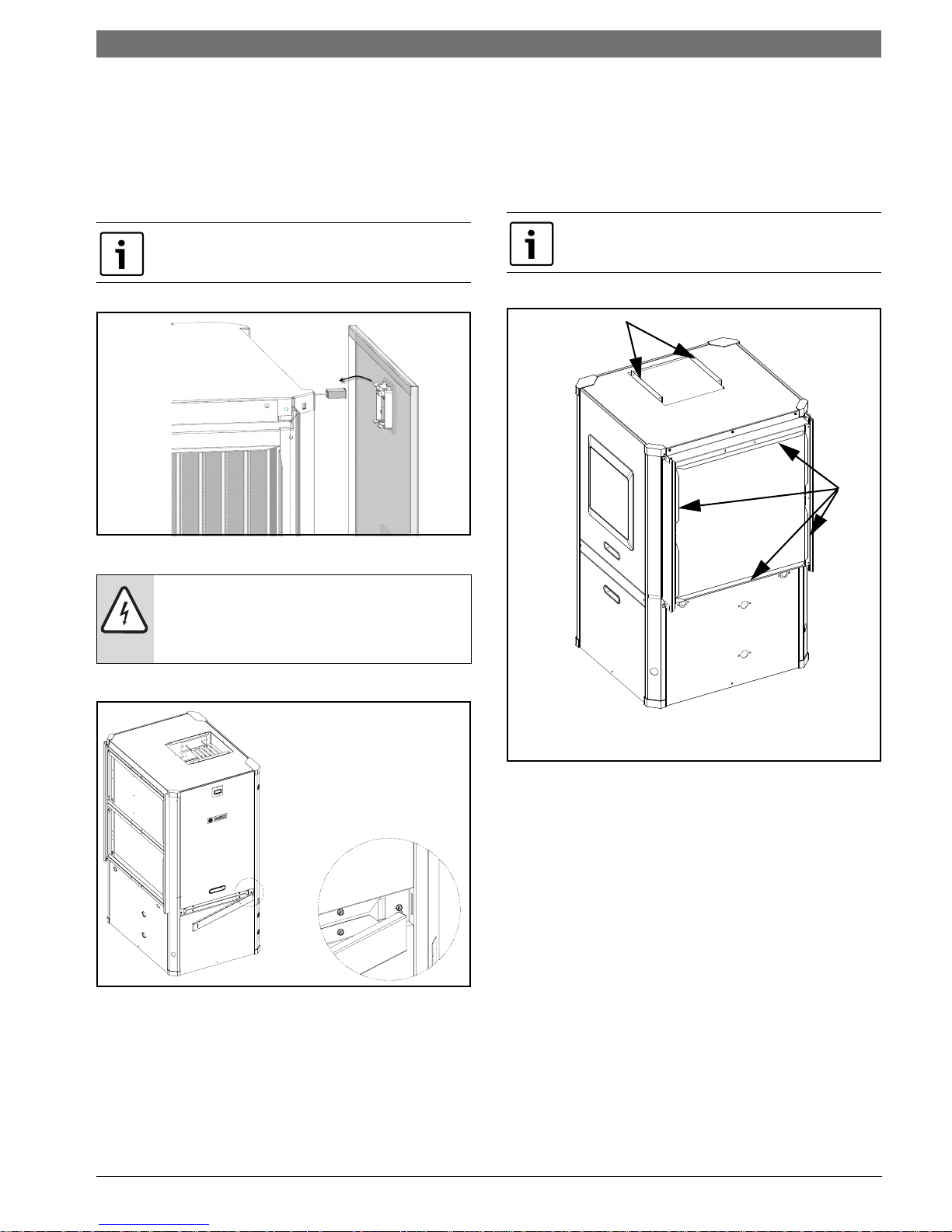
Access to Internal Components
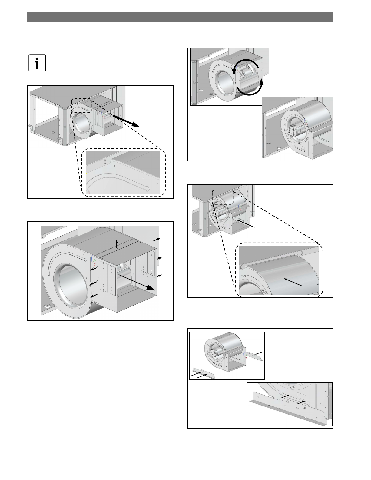
1. Using a Flat Screw driver remove and retain
Panel Belt by inserting the screwdriver into the
slot and releasing the catch.
(Figures#42and#43)
The belt is held in place by a clip on one side
and an interference fit on the other end.
Right return,
left
discharge
Left return,
right
discharge
Required Tools
• 5/16" hex head driver
•3/8" hex head driver
• 7/16" hex head driver
• Flat screw driver
• Phillips screw driver
•1/4" hex head driver
• Needle nose pliers
Figure # 42
6 720 220 406 (2015/02)Revised 02-15
16 | Vertical Configurability
1) UP
2) AWAY
1) UP
2) AWAY
Figure # 43
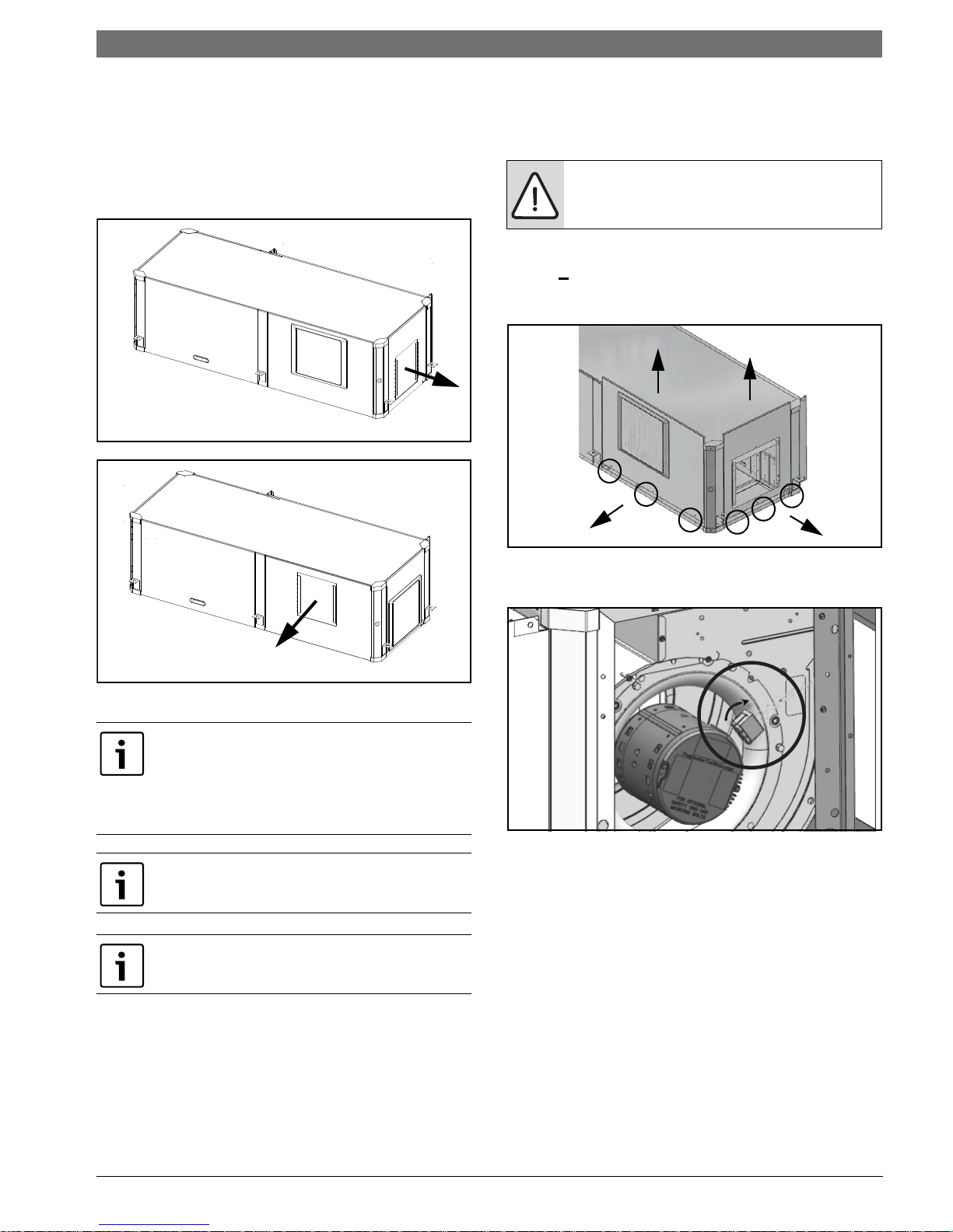
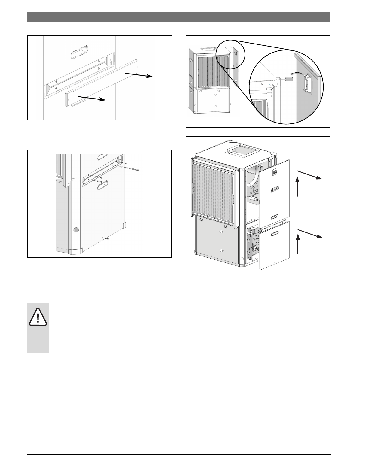
2. Remove and retain Condensing Section access
panels (bottom panel) by removing (3) screws.
(Figure #44)
SM Series Heat Pump
Figure # 45
Figure # 44
3. Remove and retain Air Handler Panel by lifting
up and out as shown in Figure #46. Remove
panel about 12" away from the cabinet and
unplug LCD screen wiring. (Figures #45
and#46)
The unit panel mounted diagnostic display
is connected to the heat pump controls with
a wire harness. Use care when removing the
display panel and carefully disconnect and
reconnect the harness when repositioning
the panel.
Figure # 46
4. Repeat steps 1–3 for all three sides.
SM Series Heat Pump6 720 220 406 (2015/02) Subject to change without prior notice
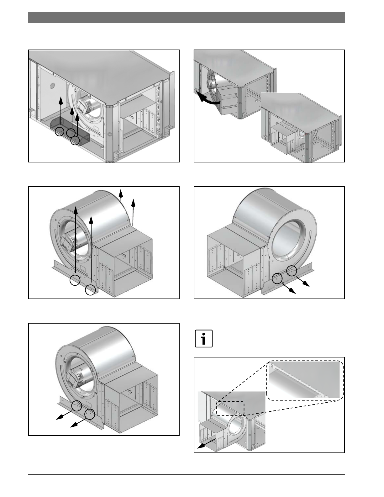
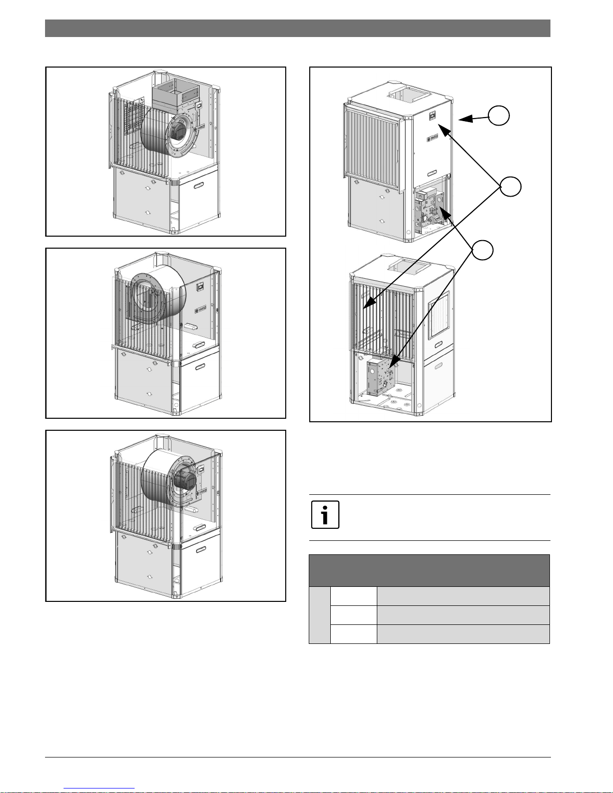
Blower Re-Configuration
This instruction details re-configuration of
blower from UP to SIDE discharge. Reconfiguration to other side uses similar steps.
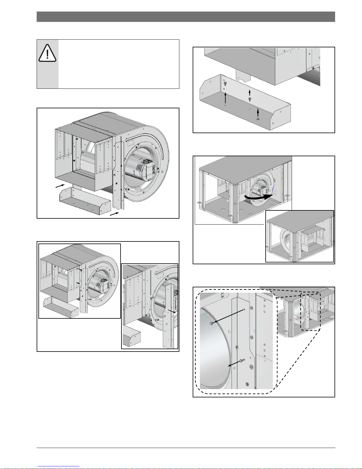
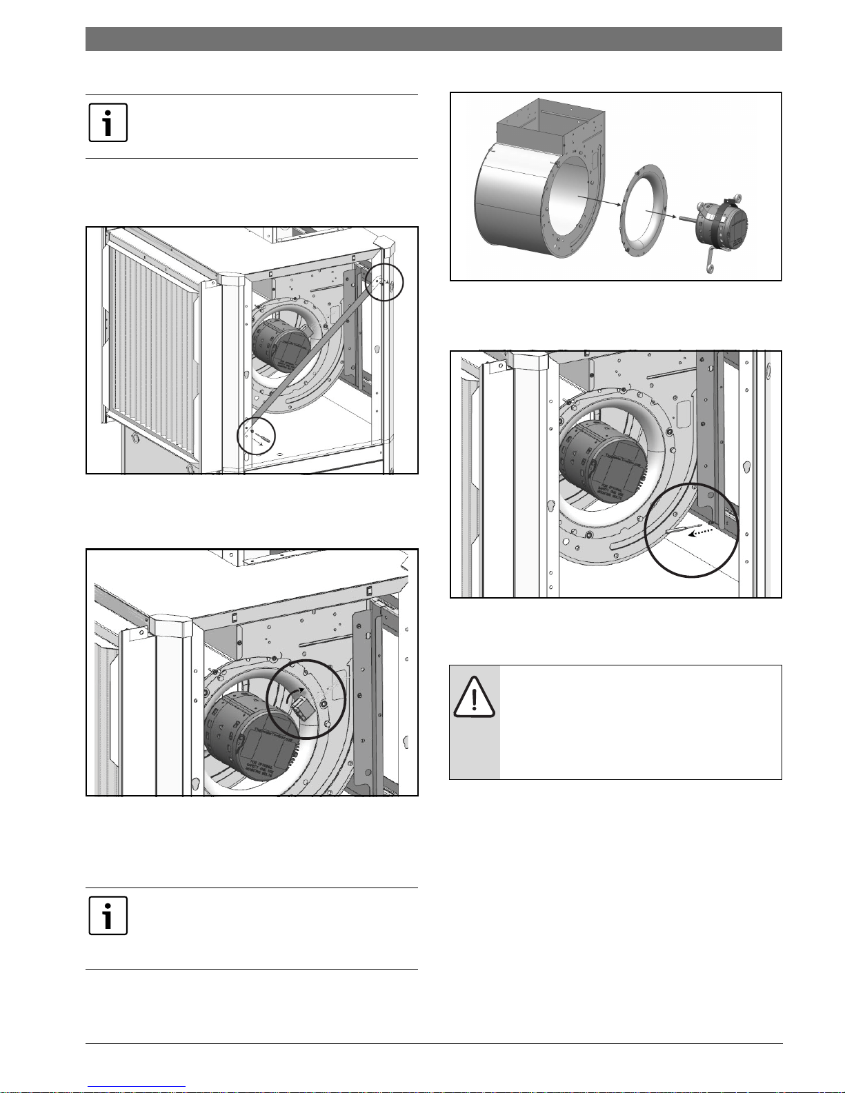
1. Remove and retain diagonal support brackets
on Front and Back sides of the unit. (Figure
#47)
Vertical Configurability | 17SM Series Heat Pump
Figure # 49
4. Remove screws on both sides of the blower
securing vertical blower bracket to horizontal
support.(Figure#50)
Figure # 47
2. Unplug electrical connections of Blower motor
and ground wire connected to blower housing.
(Figure #48)
Figure # 48
3. Remove and retain blower motor and inlet ring
assembly by removing (3) bolts securing
blower motor bracket and screws securing the
blower inlet ring. (Figure #49)
Figure # 50
5. Remove and retain blower assembly by lifting
up. (Figure #51)
Air coil is in close proximity to the blower
and air coil fins are easily damaged. Great
care must be taken during this step to avoid
coil damage. Shipping cardboard can be
used as protection during blower removal
and installation.
Removing the blower motor and blower wheel
greatly simplifies handling of the blower
assembly and reduces the chance of damaging
heat pump components.
6 720 220 406 (2015/02)Revised 02-15
18 | Vertical Configurability
1
2
FRONT OF THE PANEL VIEW
Figure # 51
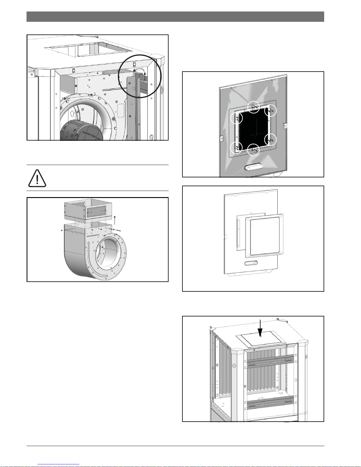
6. Remove and discard blower collar. (Figure
#52)
Discharge air configuration change is not
possible on Heat Pumps equipped with
Electric Heat Option.
SM Series Heat Pump
7. Remove and retain side panel blower opening
cover by removing (6) phillips head screws and
cutting/tearing insulation at perforations
around the perimeter of cover.(Figures #53
and #54)
Figure # 53
Figure # 52
Figure # 54
8. Reinstall blower opening cover in the TOP
panel. (Figure #55)
Figure # 55
SM Series Heat Pump6 720 220 406 (2015/02) Subject to change without prior notice
Vertical Configurability | 19SM Series Heat Pump
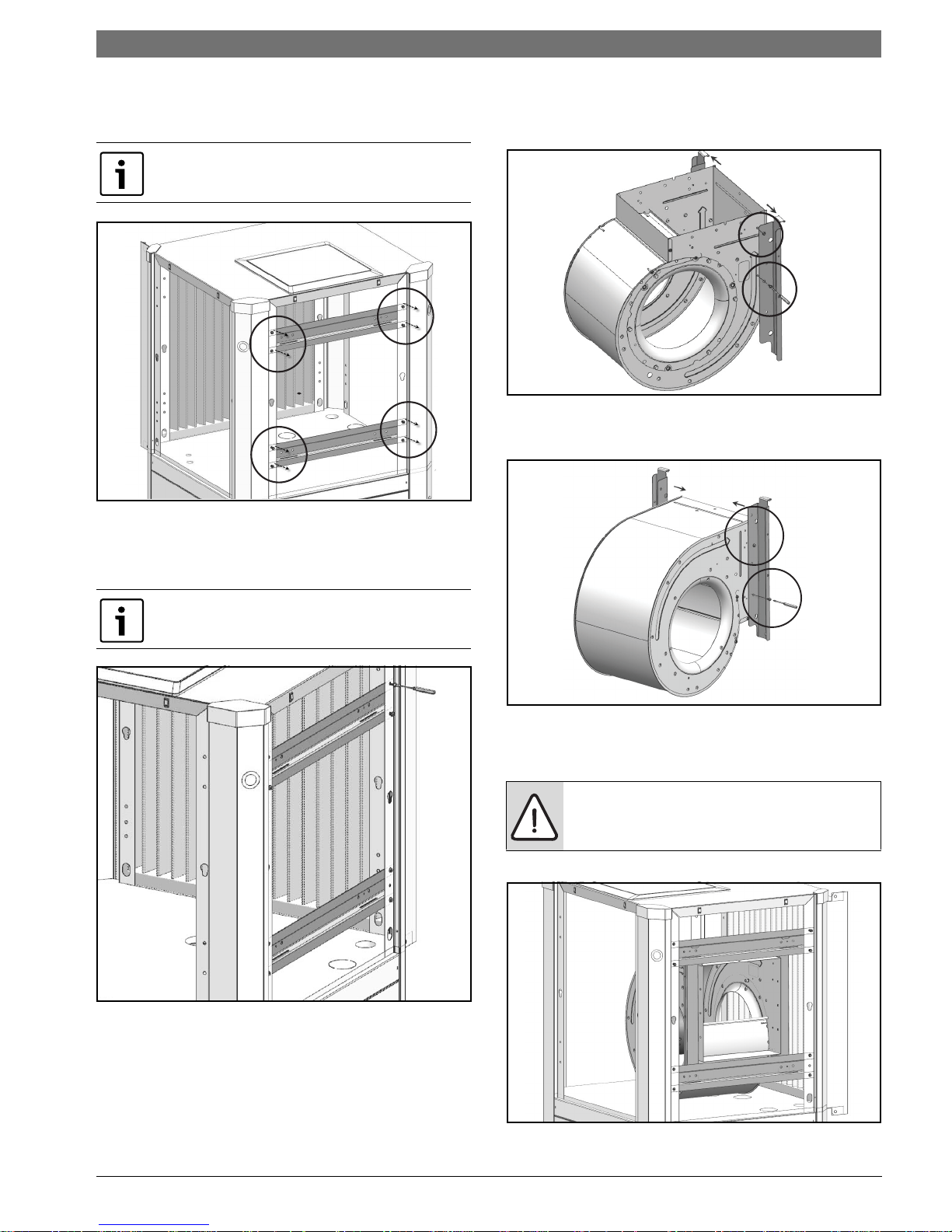
9. Remove and retain (2) horizontal blower
support brackets by removing (4) screws in
each. (Figure #56)
Upper bracket contains two push-in rubber
bump stops.
Figure # 56
10. Reinstall brackets removed in Step (9) on the
same side of the unit as the blower outlet.
(Figure #57)
11. Remove and retain vertical brackets from
blower by removing (4) screws, (2) on each
side of the blower. (Figure #58)
Figure # 58
12. Reinstall vertical brackets in new orientation.
(Figure #59)
Ensure bracket with push-in rubber bump stops
is installed in the top position.
Figure # 57
Figure # 59
13. Reinstall the blower assembly in the new
desired location, using the existing holes.
(Figure
#60)
NOTE: Be aware of blower housing
proximity to air side coil and potential for
coil damage.
Figure # 60
6 720 220 406 (2015/02)Revised 02-15
20 | Vertical Configurability
SM Series Heat Pump
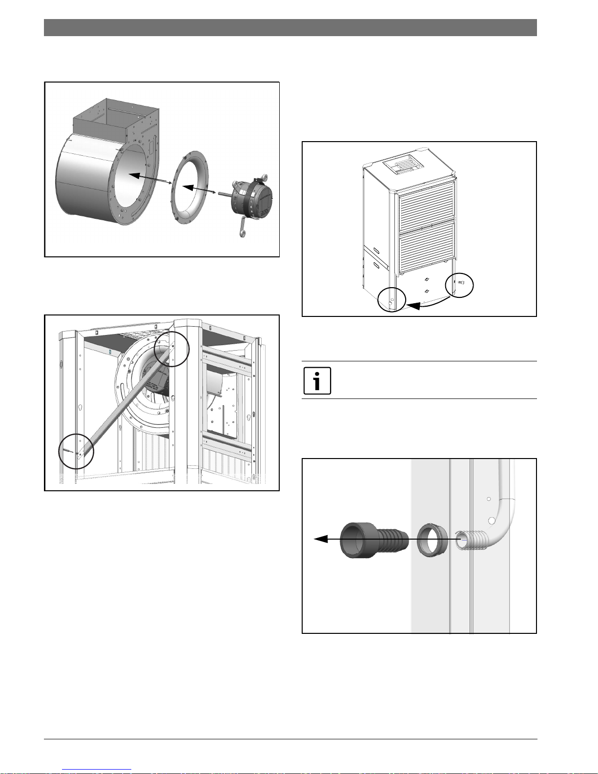
14. Reinstall blower motor and inlet ring assembly
by reversing Step #6. (Figure #61)
Figure # 61
15. Reconnect blower motor electrical plug and
ground wire.
16. Reinstall diagonal bracket(s). (Figure #62)
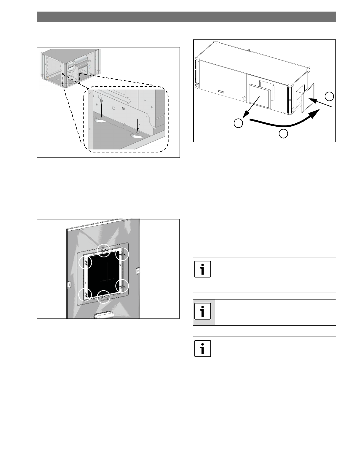
Condensate Drain Connection Reconfiguration
When re-configuring the unit from Left-Hand
Return to Right-Hand Return it is necessary to
relocate condensate drain connection from FRONT
left corner post to BACK left corner
post.(Figure#63)
Figure # 63
1. Cut the condensate drain hose on the inside of
cabinet.
Be sure to retain the spring
2. Remove and retain condensate drain plastic
fitting and grommet from the hose by pulling it
away from the hose (barb style connection).
(Figure#64)
Figure # 62
Figure # 64
SM Series Heat Pump6 720 220 406 (2015/02) Subject to change without prior notice

Vertical Configurability | 21SM Series Heat Pump
3. Locate the BACK left condensate drain and
remove and retain plastic plug covering the
cutout. (Figure#65)
Figure # 65
4. Reinstall the removed plastic plugs in the
original Condensate Drain Location.
5. Route the flexible plastic tube from FRONT left
corner post to BACK left. (Figure#66)
NOTE: Avoid kinking the hose and/or
creating a dip which could act as a second
internal p-trap. Double trapped drain lines
will not drain properly.
8. Reinstall condensate drain plastic fitting and
bushing in its new location.(Figure#67)
Figure # 67
HRP Switch Relocation
The HRP Pump Disconnect Switch is shipped loose
inside unit E-Box, to be connected to either FRONT
right corner post or BACK right corner
post.(Figure#68)
Figure # 66
6. Measure and cut the condensate drain hose to
the appropriate length.
7. Insert spring onto condensate drain hose.
Figure # 68
1. From the inside of the unit remove (2) wires
connected to HRP Pump Disconnect Switch.
6 720 220 406 (2015/02)Revised 02-15
22 | Vertical Configurability
1
2
SM Series Heat Pump
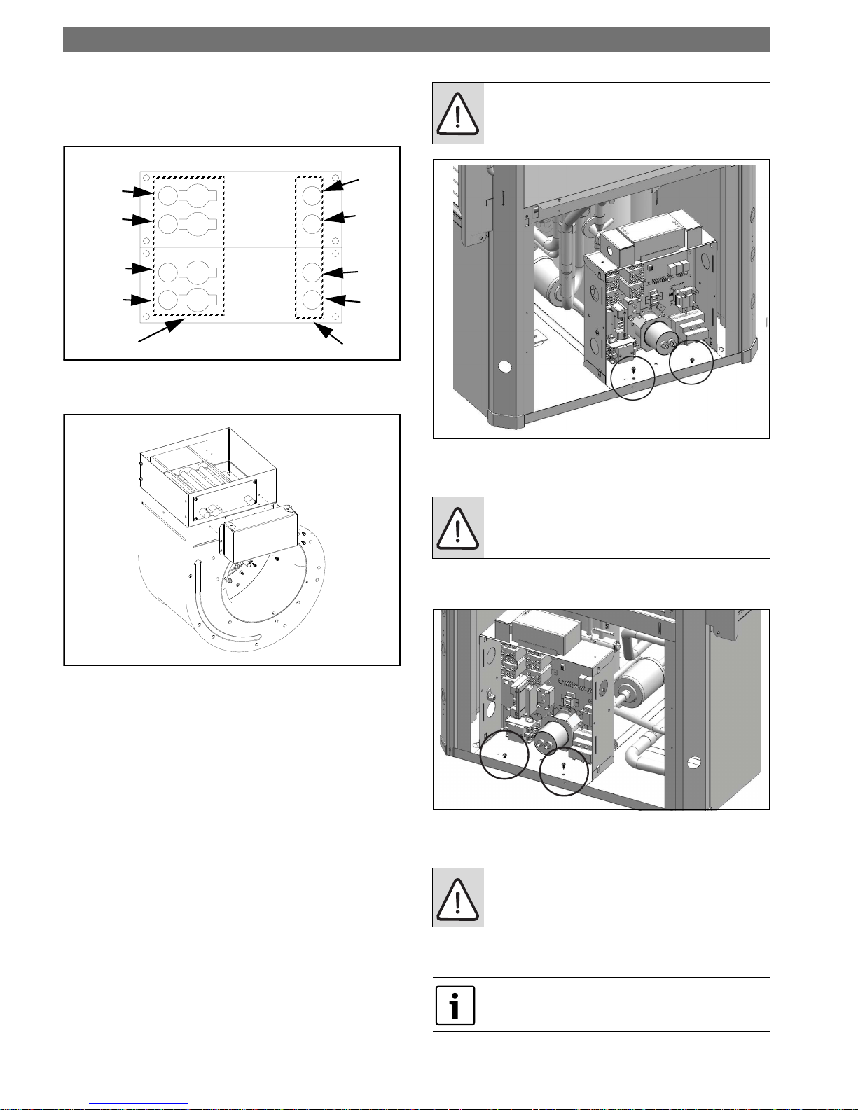
2. Identify a rectangular knockout and remove it.
Along with insulation.(Figure#69)
Figure # 69
3. Route HRP Pump Disconnect switch wires to
the new switch location.
NOTE: Do not route wiring over potentially
hot surfaces or exposed sharp edges.
Damage to wiring could result.
4. Install HRP Switch.
5. Reconnect the Switch wires.
2. Remove and retain the Electric Heat Element
cover(s) by removing (4) screws in
each.(Figure#71)
Figure # 71
3. Disconnect high voltage wiring a the Electric
Heat Elements. (Figure#72)
Electric Heat Relocation
When changing the unit from Left-Hand Return to
Right-Hand Return, it’s required to relocate
Electric Heat Components to the opposite side of
the blower in order to allow field servicing.
Electric Heat comes with (1) or (2) heating
element inserts, depending on capacity.
This instruction shows (1) heating element
insert. Perform the same steps for the
second insert, if present.
1. Identify Electric Heat components. (Figure#70)
Figure # 72
4. Remove and retain Electric Heat
Element(s).(Figure#73)
Figure # 70
[1] Electric Heat Electrical Box
[2] Electric Heat Elements.
Figure # 73
SM Series Heat Pump6 720 220 406 (2015/02) Subject to change without prior notice
Vertical Configurability | 23SM Series Heat Pump
5. Disconnect main Electric Heat E-box
plug.(FIgure#74)
Figure # 74
6. Remove and retain Electric Heat E-box by
removing (2) screws.(Figure#75)
8. Remove and retain Blower collar cover(s).
(FIgure#77)
Figure # 77
9. Re-install Electric Heat Elements in the new
location. Ensure High Temperature Cutouts are
located on the left side. (Figure#78)
Figure # 75
7. Re-install Electric Heat E-box in the new
location. (Figure#76)
Figure # 76
Figure # 78
10. Route the Unit E-box to Electric Heat wiring
harness to the new Electric Heat Element
location.
11. Connect wiring harness to the connector on
the side of Electric Heat E-Box. (Figure#79)
Figure # 79
6 720 220 406 (2015/02)Revised 02-15
24 | Vertical Configurability
HT-4
HT-3
HT-2
HT-1
HLS-1
HLS-2
HLS-3
HLS-4
BLACK
RED
SM Series Heat Pump
12. Reconnect high voltage wiring from Electric
Heat E-Box and Heating Element(s) matching
wire number to terminals as
shown.(Figure#80)
Figure # 80
13. Re-install Electric Heat Elements Cover(s).
(Figure#81)
CAUTION: take great care to ensure all
wires are disconnected and none of the
wires are 'snagged' on any components
Figure # 82
4. Reroute all of the disconnected wire bundles
to the opposite side of the heat pump.
Figure # 81
Electrical Box re-configuration
E-box is designed to be removable to support field
configuration of unit: Left-Hand Return and RightHand Return, and also to allow full access to
compressor during servicing.
The Electrical box (E-Box) has a set of plugs that
allows complete removal from the system while
keeping the majority of its internal connections.
(FIgure#123 & #124, Pg#72 and Pg#73)
1. Disconnect wiring harness by unplugging the
following plugs: P18, P19, P20 and P23 (P12 if
unit is equipped with Electric Heat).
(FIgure#123 & #124, Pg#72 and Pg#73)
2. Disconnect compressor plugs at compressor.
3. Remove and retain Electric Box by removing
(2) screws. (Figure #82)
NOTE: Do not route wiring over potentially
hot surfaces or exposed sharp edges.
Damage to wiring could result.
5. Install E-box in its new location by installing (2)
screws. (Figure #83)
Figure # 83
6. Reconnect all the wiring disconnected in Step
#1.
NOTE: Ensure all connectors are properly
oriented and are fully engaged.
7. Identify and re-route LCD wiring harness to the
new location.
Panel containing LCD always mounts on the
same side as E-Box.
SM Series Heat Pump6 720 220 406 (2015/02) Subject to change without prior notice
Return and Discharge Duct Flanges | 25SM Series Heat Pump
8. Swap FRONT panel (containing LCD) to the
BACK
Reinstall All Panels
1. Re-route the LCD wiring to the new location
and reconnect LCD screen wiring. Reinstall
panels. (Figure #84)
Panel containing LCD and Bosch Logo must be
installed on the same side as Electrical Box.
Figure # 84
RETURN AND DISCHARGE DUCT
FLANGES
Return and discharge opening duct flanges are
shipped unfolded. Flanges bend lines are
perforated allowing easy bending using standard
sheet metal pliers or channel locks. (Figure #90)
Bend flanges one at a time.
NOTE: When re-installing panel, the “RED”
cable from the LCD connector must be
connected to the “R” terminal of the LCD
PCB. The LCD will not work any other way.
2. Reinstall belts. (Figure#85)
Figure # 85
6 720 220 406 (2015/02)Revised 02-15
26 | Pre Installation Unit Preparation
T
B
A
T2
T1
T1
T1
T2
T2
A
A
A
A
SM Series Heat Pump
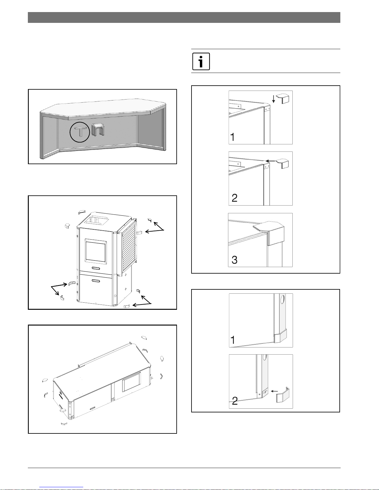
PRE INSTALLATION UNIT PREPARATION
Corner Cap Installation Instructions
Each corner cap is stamped with one the following
identifiers: T, T1,T2 B, B1, B2, A.
1. Identify Letter code on each Corner Cap.
(Figure#86)
Figure # 86
2. In preparation for installation identify each
Corner Cap location. (VT & CF Figure#87 and
HZ Figure#88)
3. Remove adhesive backing and install each
Corner Cap. (Figure#89 and#90)
Ensure cabinet surface is clean and free of
debris to ensure proper Corner Cap Adhesion.
Figure # 87
Figure # 88
Figure # 89
Figure # 90
SM Series Heat Pump6 720 220 406 (2015/02) Subject to change without prior notice
Mounting Vertical Units | 27SM Series Heat Pump
VIBRATION
PAD FULL SIZE
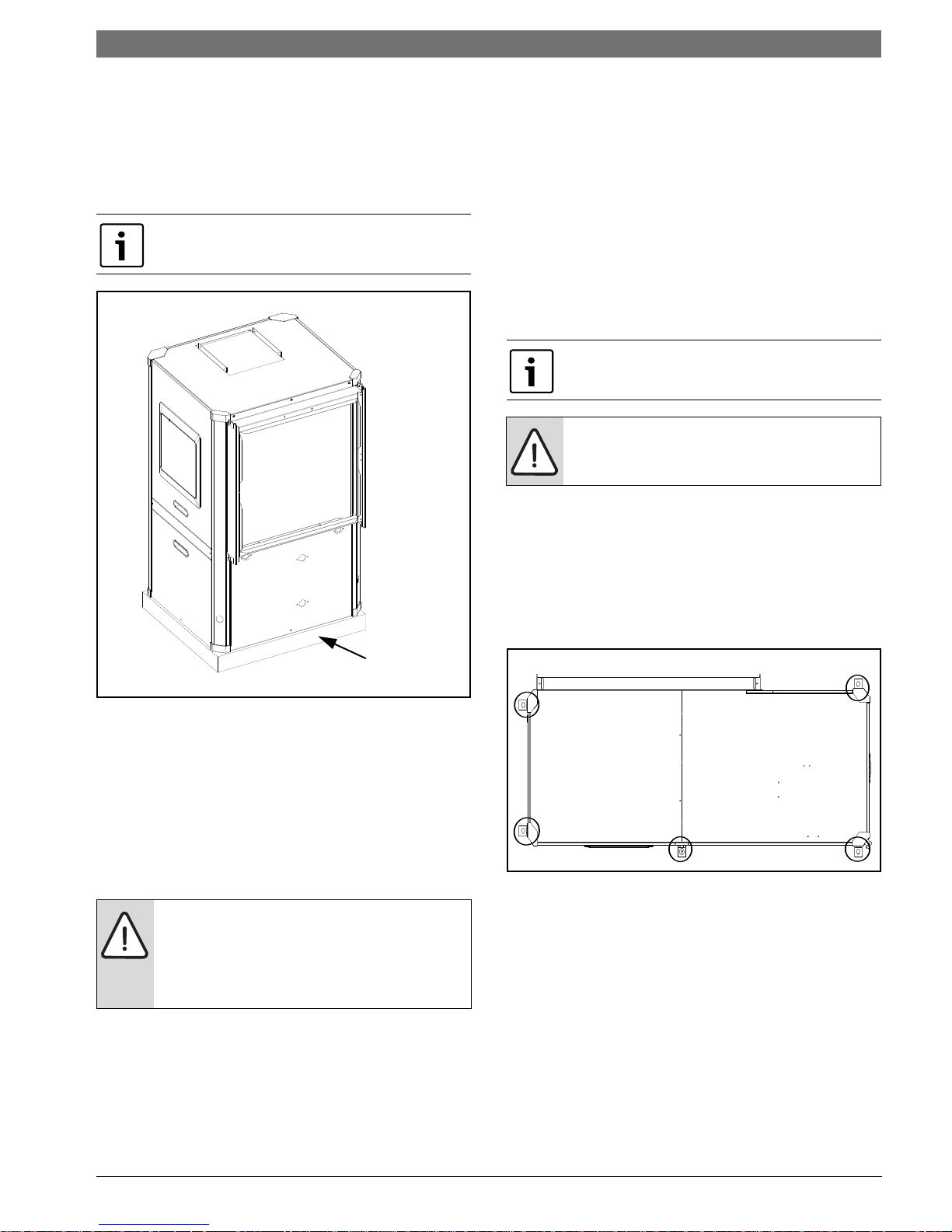
MOUNTING VERTICAL UNITS
Vertical units should be mounted level on a
vibration absorbing pad slightly larger than the
base to minimize vibration transmission to the
building structure. It is not necessary to anchor the
unit to the floor. (Figure #91).
On VT and CF Units Condensate Drain pan is
internally sloped. There is no internal P-Trap.
The secondary drain pan prevents possible
condensate overflow or water leakage damage to
the ceiling.
The secondary drain pan is usually placed on a
plywood base isolated from the ceiling joists by
additional layers of vibration absorbing mesh. In
both cases, a 3/4”drain connected to this
secondary pan should be run to an eave at a
location that will be noticeable.
If the unit is located in a crawl space, the bottom
of the unit must be at least 4” above grade to
prevent flooding of the electrical parts due to
heavy rains.
HZ Units Condensate Drain pan is NOT
internally sloped.
NOTE: Horizontal (HZ) units must be
installed pitched toward the Condensate
Drain Connection 1/8” per foot.
HANGING BRACKET KIT
Installation Instructions
All horizontal units come with hanging bracket
installation kit to facilitate suspended unit
mounting using threaded rod.Hanging brackets are
to be installed as shown in Figure #92.
Figure # 91
MOUNTING HORIZONTAL UNITS
While horizontal units may be installed on any level
surface strong enough to hold their weight, they
are typically suspended above a ceiling by
threaded rods. The manufacturer recommends
these be attached to the unit corners by hanger
bracket kits. The rods must be securely anchored
to the ceiling. Refer to the hanging bracket
assembly and installation instructions for details.
WARNING: Horizontal units installed above
the ceiling must conform to all local codes.
An auxiliary drain pan if required by code,
should be at least four inches larger than
the bottom of the heat pump.
Plumbing connected to the heat pump must not
come in direct contact with joists, trusses, walls,
etc. Some applications require an attic floor
installation of the horizontal unit. In this case the
unit should be set in a full size secondary drain pan
on top of a vibration absorbing mesh.
Figure # 92
This kit includes the following:
(5) Brackets
(5) Rubber Vibration isolators
(8) Screws #10x1/2 (not used for these models)
(10) Bolts 1/4-28x12” Hex bolt
The following are needed and are to be field
provided:
Threaded rod (3/8“ max dia)
Hex nuts
Washers (1-3/4“ min O.D.)
6 720 220 406 (2015/02)Revised 02-15
28 | Condensate Drain
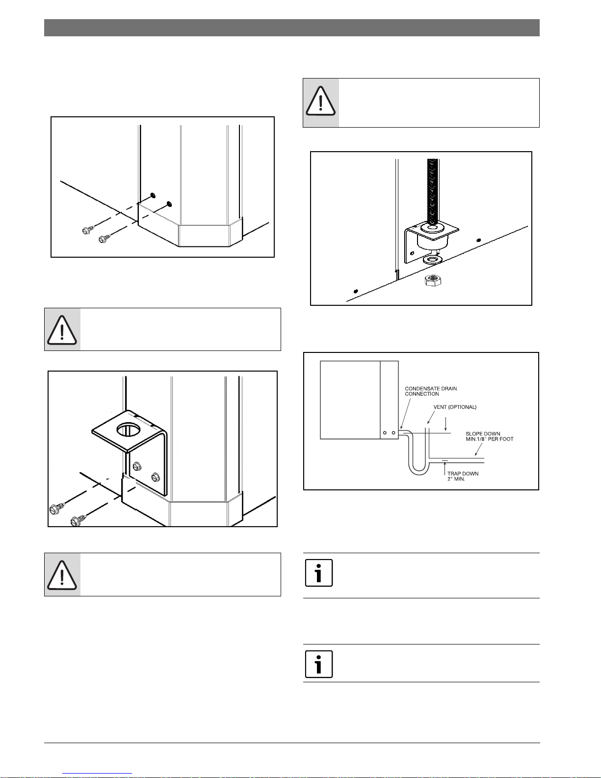
1. Remove and discard factory provided screws
from locations where hanging brackets will be
installed shown in Figure #93
Figure # 93
2. Mount 5 brackets to unit corner post using the
Bolts provided in the kit as shown on Figure # 94
SM Series Heat Pump
WARNING:Rods must be securely anchored
to the ceiling
WARNING: Do not re-use screws removed
from the unit on step 1 to mount the
hanging brackets to the unit.
Figure # 94
WARNING: Follow all applicable codes and
requirements when hanging this unit,
selecting threaded rod material, etc.
Figure # 95
CONDENSATE DRAIN
Figure # 96
A drain line must be connected to the heat pump
and pitched away from the unit a minimum of 1/8”
per foot to allow the condensate to flow away from
the unit.
When converting unit from left-hand return to
right-hand return, condensate drain connection
must be relocated. Refer to Pg#20.
3. Install rubber grommet onto the brackets as
shown in Figure # 95
4. Hang the unit and assemble the field provided
Thread rod, nuts and washers on to the brackets as
shown in Figure # 95
This connection must be in conformance with local
plumbing codes. A trap must be installed in the
condensate line to insure free condensate flow.
HZ Heat Pump Drain Pan is not internally
sloped.
SM Series Heat Pump6 720 220 406 (2015/02) Subject to change without prior notice
Duct System | 29SM Series Heat Pump
A vertical air vent is sometimes required to avoid
air pockets. The length of the trap depends on the
amount of positive or negative pressure on the
drain pan. A second trap must not be included.
DUCT SYSTEM
A supply air outlet collar and return air duct flange
are provided on all units to facilitate duct
connections.
Supply air duct and return air duct flanges are
shipped unfolded with unit.
Fold the duct flange outwards along the perforated
line. Refer to unit Dimensional Drawings for
physical dimensions of the collar and flange.
(Pg#95 through Pg#95)
A flexible connector is recommended for supply
and return air duct connections on metal duct
systems. All metal ducting should be insulated
with a minimum of one inch duct insulation to
avoid heat loss or gain and prevent condensate
forming during the cooling operation. Application
of the unit to the no insulated duct work is not
recommended as the unit’s performance will be
adversely affected.
NOTE: Do not connect discharge ducts
directly to the blower outlet.
PIPING
Supply and return piping must be as large as the
unit connections on the heat pump (larger on long
runs).
NOTE: Never use flexible hoses of a smaller
inside diameter than that of the fluid
connections on the unit.
SM units are supplied with either a copper or
optional cupro-nickel condenser. Copper is
adequate for ground water that is not high in
mineral content.
Proper testing is recommended to assure the
well water quality is suitable for use with water
source equipment. When in doubt, use cupronickel.
In conditions anticipating moderate scale
formation or in brackish water a cupro-nickel heat
exchanger is recommended.
Refer to water quality table on page #30
Both the supply and discharge water lines will
sweat if subjected to low water temperature.
These lines should be insulated to prevent damage
from condensation. All manual flow valves used in
the system must be ball valves. Globe and gate
valves must not be used due to high pressure drop
and poor throttling characteristics.
The factory provided air filter must be removed
when using a filter back return air grill. The factory
filter should be left in place on a free return
system.
If the unit will be installed in a new installation
which includes new duct work, the installation
should be designed using current ASHRAE
procedures for duct sizing. If the unit is to be
connected to existing duct work, a check should
be made to assure that the duct system has the
capacity to handle the air required for the unit
application. If the duct system is too small, larger
duct work should be installed. Check for existing
leaks and repair.
The duct system and all diffusers should be sized
to handle the designed air flow quietly. To
maximize sound attenuation of the unit blower, the
supply and return air plenums should be insulated.
There should be no direct straight air path thru the
return air grille into the heat pump. The return air
inlet to the heat pump must have at least one 90
degree turn away from the space return air grille. If
air noise or excessive air flow are a problem, the
blower speed can be changed to a lower speed to
reduce air flow.
NOTE: Never exceed the recommended
water flow rates as serious damage or
erosion of the water-to-refrigerant heat
exchanger could occur.
Always check carefully for water leaks and repair
appropriately. Units are equipped with swivel
female pipe thread fittings. Consult Unit
Dimensional Drawings. (Pg#95 through Pg#95)
Teflon tape sealer should be used when
connecting water piping connections to the units
to insure against leaks and possible heat
exchanger fouling.
NOTE: Do not overtighten the connections.
Flexible hoses should be used between the unit
and the rigid system to avoid possible vibration.
Ball valves should be installed in the supply and
return lines for unit isolation and unit water flow
balancing.
6 720 220 406 (2015/02)Revised 02-15
30 | Water Quality
WATER QUALITY
Table 1: Water Quality
SM Series Heat Pump
POTENTIAL
PROBLEM
SCALING
CORROSION
Water Characteristic Acceptable Value
Copper Cupro-Nickel
pH (Acidity/Alkalinity) 7-9 7-9
Hardness (CaCO3,
MgCO3)
Ryznar Stability Index
Langelier Saturation Index
Hydrogen Sulfide (H2S) < 0.5 ppm * 10-50 ppm
Sulfates
Chlorine
Chlorides
Carbon Dioxide
Ammonia
Ammonia Chloride
Ammonia Nitrate
Ammonia Hydroxide
< 350 ppm < 350 ppm
6.0 - 7.5 6.0 - 7.5
-0.5 - +0.5 -0.5 - +0.5
< 125 ppm < 125 ppm
< 0.5 ppm < 0.5 ppm
< 20 ppm < 150 ppm
< 50 ppm < 50 ppm
< 2 ppm < 2 ppm
< 0.5 ppm < 0.5 ppm
< 0.5 ppm < 0.5 ppm
< 0.5 ppm < 0.5 ppm
Ammonia Sulfate
Dissolved Solids
IRON FOULING
EROSION
* No "rotten egg" smell present at < 0.5 ppm H2S.
** Equivalent to 30 mesh strainer
Iron (Fe2+ Iron Bacteria
Potential)
Iron Oxide
Suspended Solids < 10 ppm, < 600 μm size ** < 10 ppm, < 600 μm size **
Maximum Water Velocity
ELECTRICAL
Refer to electrical component box layout.
(Figure #97)
WARNING: Field wiring must comply
with local and national electric codes.
WARNING: Power to the unit must be
within the operating voltage range
indicated on the unit nameplate or on
the performance data sheet.
< 0.5 ppm < 0.5 ppm
< 1,000 ppm < 1,500 ppm
< 0.2 ppm < 0.2 ppm
< 1 ppm < 1 ppm
6 ft/sec 6 ft/sec
NOTE: Operation of unit on improper
line voltage or with excessive phase
imbalance will be hazardous to the unit,
constitutes abuse and may void the
warranty.
Properly sized fuses or HACR circuit breakers must
be installed for branch circuit protection. See unit
nameplate for maximum fuse or breaker size.
SM Series Heat Pump6 720 220 406 (2015/02) Subject to change without prior notice
 Loading...