

Bosch SM024, SM036, SM060, SM070, SM048 Installation, Operation And Maintenance Manual
...
SM CS Series Heat pump
SM024 | SM036 | SM048 | SMO60 | SM070
Installation, Operation and Maintenance Manual
8 733 920 846 (2013/11)
2 | SM CS Series Heat Pump
CONTENTS
Model Nomenclature.......................................................... 3
Key to Symbols.................................................................. 3
Safety Warnings ................................................................ 3
Standard SM CS package ................................................... 4
General Description........................................................... 4
Moving and Storage ........................................................... 4
Initial Inspection ............................................................... 4
Location............................................................................ 4
Condensing Section ..................................................... 4
Air Handler ................................................................. 5
Piping ............................................................................... 5
Electrical .......................................................................... 6
Options........................................................................... 10
Heat Recovery Package (HRP) ..................................... 10
DPS Water Flow Proving ............................................. 10
Pump Relay............................................................... 10
Comfort Alert Module ................................................. 10
Maintenance ...................................................................20
Unit Check-Out Sheet .......................................................21
Troubleshooting ..............................................................22
Unit Lockouts ............................................................ 25
Operating Temperatures and Pressures ............................26
Water Side Pressure Drop Table........................................31
Wiring Diagrams ..............................................................32
Dimensional Drawings......................................................33
Spare Parts List ...............................................................34
Notes .............................................................................. 39
Heat Recovery Package ................................................... 11
Water Tank Preparation .............................................. 11
HR Water Piping ........................................................ 11
Water Tank Refill........................................................ 12
Initial Start-Up........................................................... 12
Sequence of Operation .................................................... 13
Cooling Mode ............................................................ 13
Heating Mode............................................................ 13
Application Considerations .............................................. 15
Well Water Systems ................................................... 15
Cooling Tower/Boiler Systems ..................................... 16
Geothermal Systems .................................................. 18
System Checkout ............................................................ 19
Unit Start-up ................................................................... 19
Figure 1: CS/AH Pairings
UNIT MODEL
Unit 1 Unit 2 Unit 3 Unit 4 Unit 5 Unit 6
SM024-1CSC
SM036-1CSC
SM048-1CSC
SM060-1CSC
SM070-1CSC
LEGEND:
AVX BOSCH box style Vertical Air Handler
AHX BOSCH box style Horizontal Air Handler
CCX Cased coil
UCX Uncased coil
VTX Motex unitary style air handler
SM024-1AVX
SM036-1AVX
SM048-1AVX
SM060-1AVX
SM070-1AVX
SM024-1AHX DX025-1VTX DX025-1CCX DX025-1UCX DX035-1VTX
SM036-1AHX DX035-1VTX DX035-1CCX DX035-1UCX DX049-1VTX
SM048-1AHX DX049-1VTX DX049-1CCX DX049-1UCX
SM060-1AHX DX061-1VTX DX061-1CCX DX061-1UCX DX071-1VTX
SM070-1AHX DX071-1VTX DX071-1CCX DX071-1UCX
Paired Air Handler
SM CS Series Heat Pump8 733 920 846 (2013/11) Subject to change without prior notice
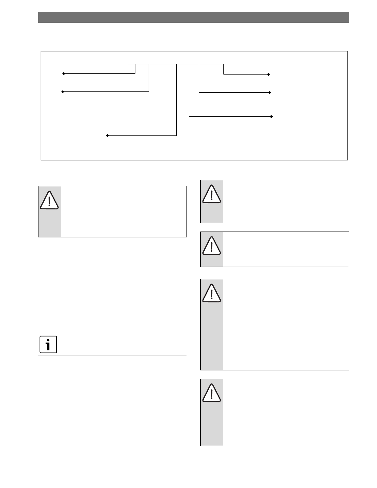
MODEL NOMENCLATURE
SM 024 - 1 CS C - F
SERIES WATER CONNECTIONS
SM F - Front
SIZE
COAX OPTIONS
024 C - Copper
036 N - Cupro-Nickel
048
060
CABINET CONFIGURATION
070 CS - Condensing Section
VOLTAGE DESIGNATIONS
1
- 208/1/60 & 230/1/60
Revision Level A
Model Nomenclature | 3SM CS Series Heat
KEY TO SYMBOLS
Warnings
Warnings in this document are identified by
a warning triangle printed against a grey
background. Keywords at the start of the
warning indicate the type and seriousness
of the ensuing risk if measures to prevent
the risk are not taken.
The following keywords are defined and can be
used in this document:
• NOTE indicates a situation that could result in
damage to property or equipment.
• CAUTION indicates a situation that could
result in minor to medium injury.
• WARNING indicates a situation that could
result in sever injury or death.
• DANGER indicates a situation that will result in
severe injury or death.
Important Information
This symbol indicates important information
where there is no risk to property or people.
SAFETY WARNINGS
Installation and servicing of this equipment
can be hazardous due to system pressure
and electrical components. Only trained
and qualified personnel should install,
repair, or service the equipment.
Before performing service or maintenance
operations on the system, turn off main
power to the unit. Electrical shock could
cause personal injury or death.
All refrigerant discharged from this unit
must be recovered WITHOUT EXCEPTION.
Technicians must follow industry accepted
guidelines and all local, state, and federal
statutes for the recovery and disposal of
refrigerants. If a compressor is removed
from this unit, refrigerant circuit oil will
remain in the compressor. To avoid leakage
of compressor oil, refrigerant lines of the
compressor must be sealed after it is
removed.
To avoid equipment damage, DO NOT use
these units as a source of heating or cooling
during the construction process. Doing so
may affect the unit’s warranty. The
mechanical components and filters will
quickly become clogged with construction
dirt and debris, which may cause system
damage.
8 733 920 846 (2013/11)Revised 11-13

4 | Standard SM CS package SM CS Series Heat Pump
1
2
STANDARD SM CS PACKAGE
Figure # 2
[1] SM Series Water-to-Air Heat Pump: Condensing
Section
[2] Installation and Operation Manual
GENERAL DESCRIPTION
SM Series Water-to-Air Heat Pumps provide the
best combination of performance and efficiency
available. All units are performance certified to
American Heating and Refrigeration Institute
(AHRI) ISO Standard 13256-1. All SM Water-to-Air
Heat Pumps conform to UL1995 standard and are
certified to CAN/CSA C22.1 No 236 by IntertekETL. The Water-to-Air Heat Pumps are designed to
operate with entering fluid temperature between
20°F to 90°F in the heating mode and between
30°F to 120°F in the cooling mode.
50°F Minimum Entering Water Temperature
(EWT) is recommended for well water
applications with sufficient water flow to prevent
freezing. Antifreeze solution is required for all
closed loop applications. Cooling Tower/Boiler
and Geothermal applications should have
sufficient antifreeze solution to protect against
extreme conditions and equipment failure.
Frozen water coils are not covered under
warranty. Other equivalent methods of
temperature control are acceptable.
Several factory installed options are available:
Heat Recovery Package, Sound Package, Smart
Start Assist, DPS Water Flow Proving Switch,
Auxiliary Pump Relay, and Comfort Alert Module.
Safety devices are built into each unit to provide
the maximum system protection possible when
properly installed and maintained.
MOVING AND STORAGE
If the equipment is not needed for immediate
installation upon its arrival at the job site, it should
be left in its shipping carton and stored in a clean,
dry area. Units must only be stor e d or mov e d in the
normal upright position as indicated by the “UP”
arrows on each carton at all times.
For storage If unit stacking is required,
stack units as follows:
Do not stack units larger than 6 tons!
INITIAL INSPECTION
Be certain to inspect all cartons or crates on each
unit as received at the job site before signing the
freight bill. Verify that all items have been received
and that there are no visible damages; note any
shortages or damages on all copies of the freight
bill. In the event of damage or shortage, remember
that the purchaser is responsible for filing the
necessary claims with the carrier. Concealed
damages not discovered until after removing the
units from the packaging must be reported to the
carrier within 24 hours of receipt.
LOCATION
To maximize system performance, efficiency and
reliability, and to minimize installation costs, it is
always best to keep the refrigerant lines as short
as possible. Every effort should be made to locate
the air handler and the condensing section as
close as possible to each other.
Condensing Section
Locate the condensing section in an area that
provides sufficient room to make water and
electrical connections, and allows easy removal of
the access panels, for service personnel to
perform maintenance or repair.
The condensing section is designed for indoor use
primarily; however, if the condensing section must
be installed in an outdoors location where ambient
temperatures can fall below freezing, some form of
freeze protection should be employed such as a
freeze-stat and/or a pump timer/starter to prevent
possible condenser freeze-up and to optimize
overall system performance.
SM CS Series Heat Pump8 733 920 846 (2013/11) Subject to change without prior notice
Piping | 5SM CS Series Heat
VIBRATION
PAD FULL
Air Handler
Locate the air handler unit in an indoor area that
allows easy removal of the filter and access panels,
and has enough room for service personnel to
perform maintenance or repair. Provide sufficient
room to make electrical and duct connections. If
the unit is located in a confined space such as a
closet, provisions must be made for return air to
freely enter the space. On horizontal units, allow
adequate room below the unit for a condensate
drain trap.
The air handler units are not approved for
outdoor installation; therefore, they must be
installed inside the structure being conditioned.
Do not locate in areas that are subject to
freezing.
Reference the Factory Manual for your AH or
the Air Handler section of this manual for
detailed installation and operation.
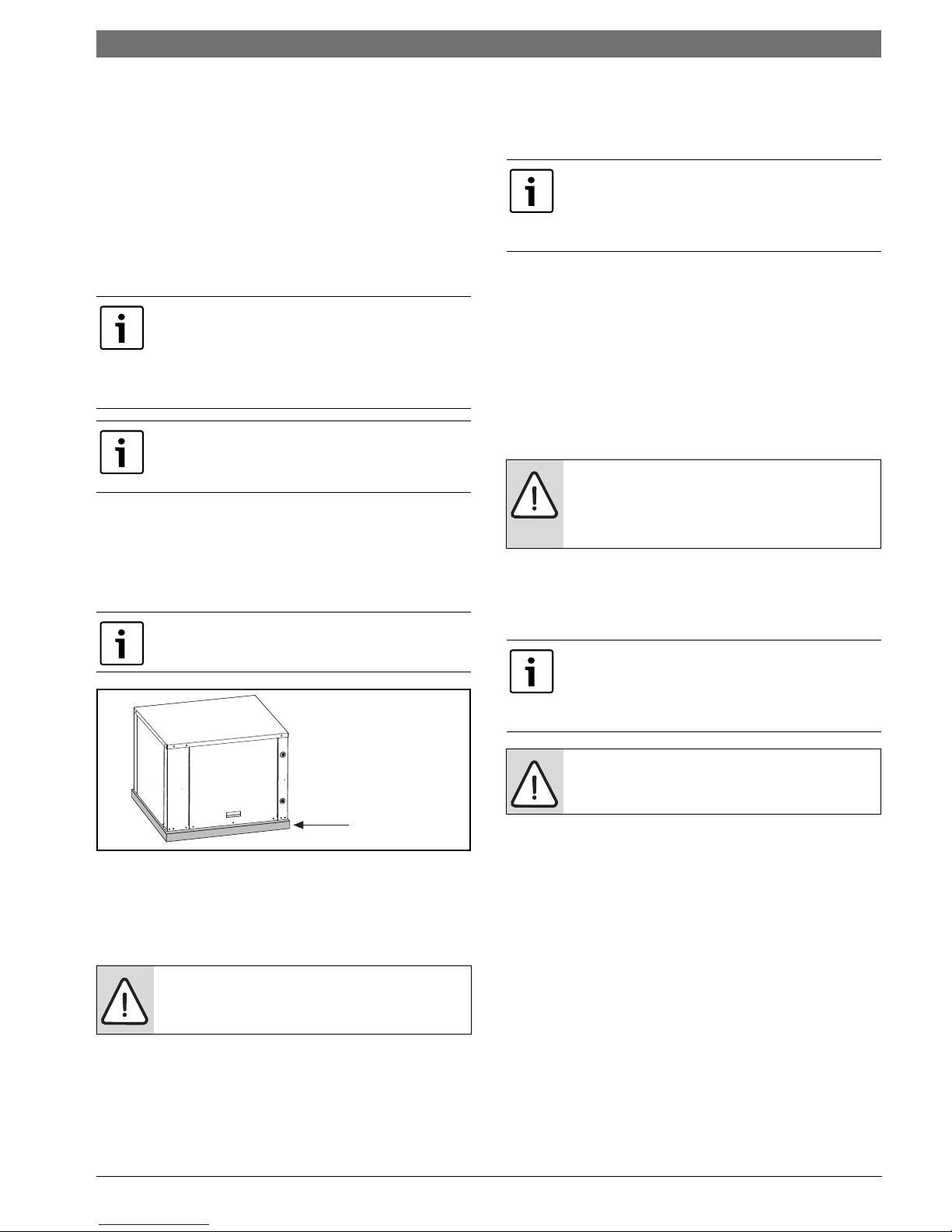
Vertical units should be mounted level on a
vibration absorbing pad slightly larger than the
base to minimize vibration transmission to the
building structure. It is not necessary to anchor the
unit to the floor. (Figure #3).
On VT and CF Units Condensate Drain pan is
internally sloped. There is no internal P-Trap.
SM units are supplied with either a copper or
optional cupro-nickel condenser. Copper is
adequate for ground water that is not high in
mineral content.
Proper testing is recommended to assure the
well water quality is suitable for use with water
source equipment. When in doubt, use cupronickel.
In conditions anticipating moderate scale
formation or in brackish water a cupro-nickel heat
exchanger is recommended.
Both the supply and discharge water lines will
sweat if subjected to low water temperature.
These lines should be insulated to prevent damage
from condensation. All manual flow valves used in
the system must be ball valves. Globe and gate
valves must not be used due to high pressure drop
and poor throttling characteristics.
Never exceed the recommended water flow
rates as serious damage or erosion of the
water-to-refrigerant heat exchanger could
occur.
Always check carefully for water leaks and repair
appropriately. Units are equipped with female pipe
thread fittings. Consult Unit Dimensional
Drawings. (Pg#91 through Pg#95)
Teflon tape sealer should be used when
connecting water piping connections to the units
to insure against leaks and possible heat
exchanger fouling.
Figure # 3
PIPING
Supply and return piping must be as large as the
unit connections on the heat pump (larger on long
runs).
Never use flexible hoses of a smaller inside
diameter than that of the fluid connections
on the unit.
Do not overtighten the connections.
Flexible hoses should be used between the unit
and the rigid system to avoid possible vibration.
Ball valves should be installed in the supply and
return lines for unit isolation and unit water flow
balancing.
8 733 920 846 (2013/11)Revised 11-13
6 | Electrical SM CS Series Heat Pump
1
2
3
4
5
6
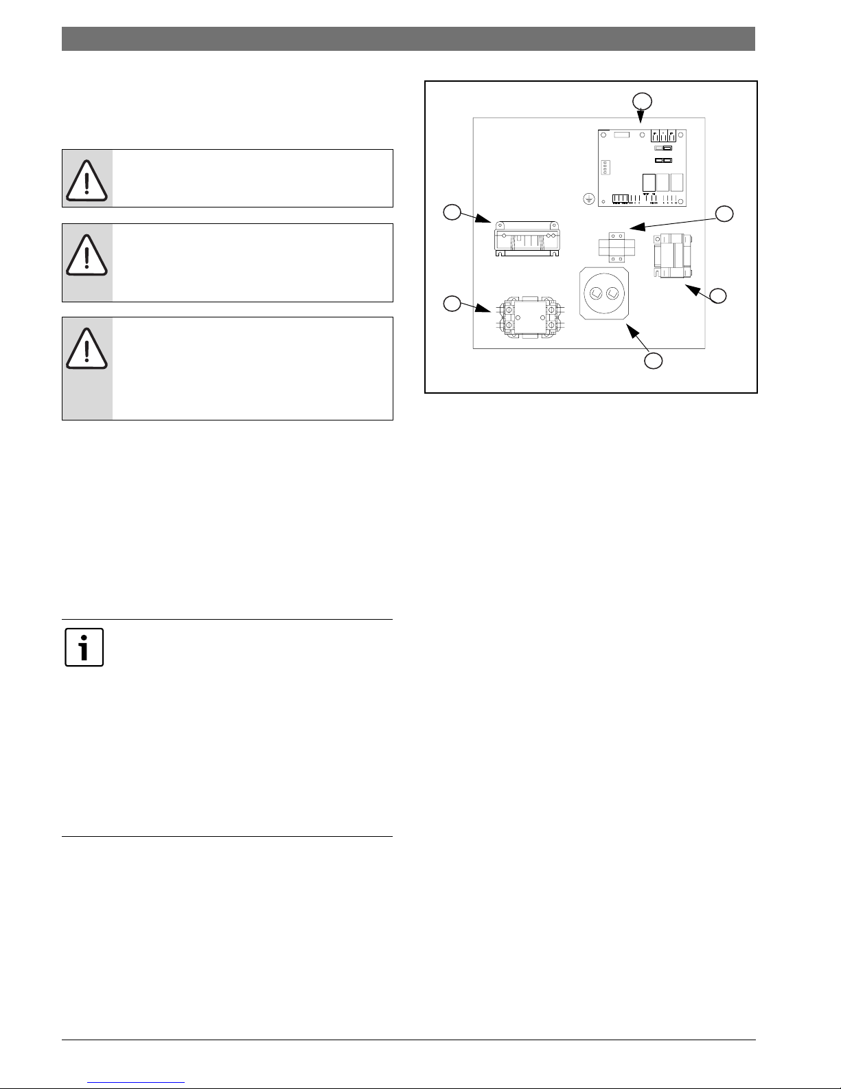
ELECTRICAL
Refer to electrical component box layout.
(Figure #4)
Field wiring must comply with local and
national electric codes.
Power to the unit must be within the
operating voltage range indicated on
the unit nameplate or on the
performance data sheet.
Operation of unit on improper line
voltage or with excessive phase
imbalance will be hazardous to the unit,
constitutes abuse and may void the
warranty.
Properly sized fuses or HACR circuit breakers must
be installed for branch circuit protection. See unit
nameplate for maximum fuse or breaker size.
The unit is provided with a concentric knock-out
for attaching common trade sizes of conduit, route
power supply wiring through this opening. Always
connect the ground lead to the grounding lug
provided in the control box and power leads to the
line side of compressor contactor as indicated on
the wiring diagram (Figures on Pg#32 through
Pg#32).
[1] Comfort Alert Module (Option)
[2] Compressor contactor
[3] Capacitor
[4] Auxiliary Relay (DP/DT)
[5] Terminal block (Option)
[6] Unit Protection Module (UPM)
Figure # 4
Units supplied with internal electric heat require
two (2) separate power supplies:
1) Unit compressor
2) Electric Heat, blower motor and control
circuit.
-------------------------------------------------------------
Refer to the ELECTRIC HEATER PACKAGE
OPTION section and Pg#32 through Pg#32 for
wiring diagrams. See data plate for minimum
circuit ampacities and maximum fuse/breaker
sizing.
SM CS Series Heat Pump8 733 920 846 (2013/11) Subject to change without prior notice
Electrical | 7SM CS Series Heat
1
2
3
4
5
6
7
9
10
11
1213
17
14
15
16
8
Safety Devices and the UPM Controller
If the thermostat is provided with a malfunction
light powered off of the hot (R) side of the
transformer, then the thermostat malfunction
light connection should be connected directly to
the (ALR) contact on the unit’s UPM board.
Each unit is factory provided with a Unit Protection
Module (UPM) that controls the compressor
operation and monitors the safety controls that
protect the unit.
Safety controls include the following:
• High pressure switch located in the refrigerant
discharge line and wired across the HPC
terminals on the UPM.
• Low pressure switch located in the unit
refrigerant suction line and wired across
terminals LPC1 and LPC2 on the UPM.
UPM Board Dry Contacts are Normally Open
(NO)
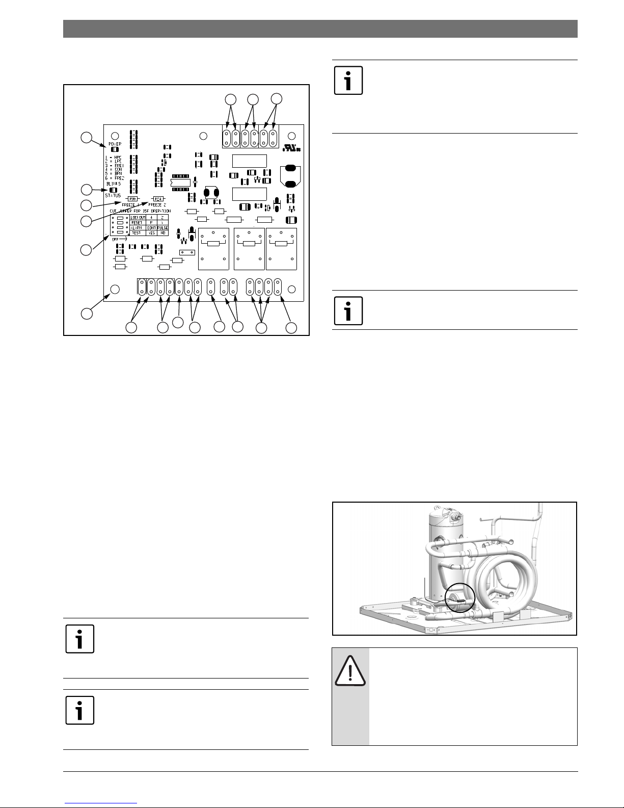
Figure # 5
[1] Board Power Indicator
[2] UPM Status LED Indicator
[3] Water Coil Freeze Protection Temperature
Selection [R30]
[4] Air Coil Freeze Protection Temperature
Selection
[5] UPM Board Settings
[6] Water Coil Freeze Connection
[7] Air Coil Freeze Connection
[8] LCD Unit Display Connection
[9] 24VAC Power Input
• Water side freeze protection sensor, mounted
close to condensing water coil, monitors
refrigerant temperature between condensing
water coil and thermal expansion valve. If
temperature drops below or remains at freeze
limit trip for 30 seconds, the controller will
shut down the compressor and enter into a
soft lockout condition. The default freeze limit
trip is 30°F, however this can be changed to
15°F by cutting the R30 or Freeze1 resistor
located on top of DIP switch SW1 (Refer to
Figure #5, item [3] for resistor location), Refer
to Figure #6 for sensor location.
[10] Compressor Contact Output
[11] High Pressure Switch Connection
[12] Call for Compressor Y1
[13] Low Pressure Switch Connection
[14] 24VAC Power Common
[15] Condensate Overflow Sensor
[16] Dry Contact
[17] UPM Ground Standoff
If the unit is being connected to a thermostat
with a malfunction light, this connection is made
at the unit malfunction output or relay. Refer to
Figure #5.
If the thermostat is provided with a malfunction
light powered off of the common (C) side of the
transformer, a jumper between “R” and “COM”
terminal of “ALR” contacts must be made.
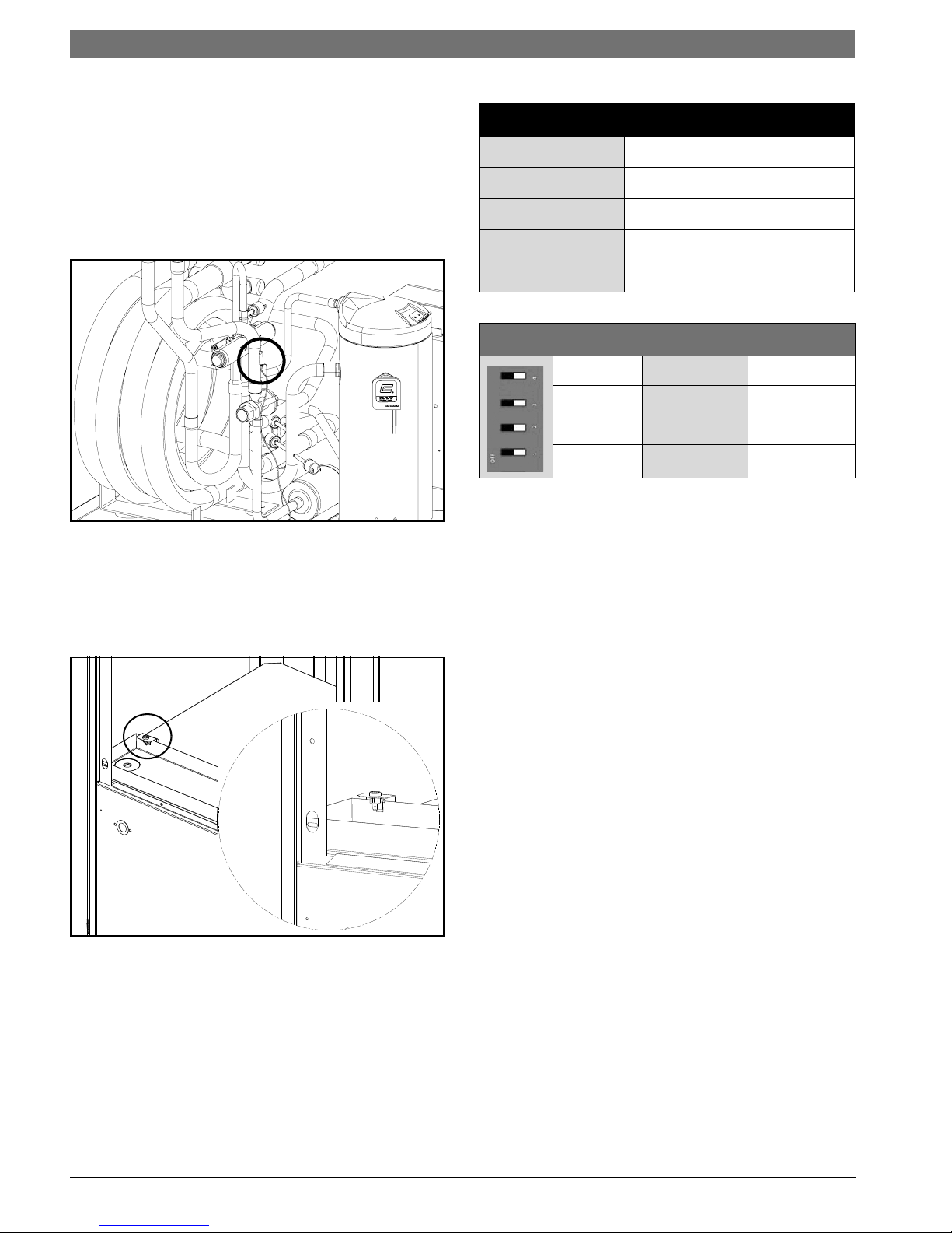
Figure # 6
If unit is employing a fresh water system (no
anti-freeze protection), it is extremely
important to have the Freeze1 R30 resistor
set to 30°F in order to shut down the unit at
the appropriate leaving water temperature
and protect your heat pump from freezing if
a freeze sensor is included.
8 733 920 846 (2013/11)Revised 11-13
8 | Electrical SM CS Series Heat Pump
• Evaporator freeze protection sensor, mounted
after the thermal expansion device and the
UPM Board Factory Default Settings
evaporator, monitors refrigerant temperature
between the evaporator coil and thermal
expansion valve. If temperature drops below or
remains at freeze limit trip for 30 seconds, the
controller will shut down the compressor and
TEMP
LOCKOUT
RESET
30°F
2
Y
enter into a soft lockout condition. The default
freeze limit trip is 30°F. (Figure#7)
ALARM
TEST
PULSE
NO
UPM DIP SWITCH DEFAULT POSITION
lockout 42
Figure # 7
• The condensate overflow protection sensor is
located in the drain pan of the unit and
connected to the ‘COND’ terminal on the UPM
board. (Figure #4)
Figure # 8
reset
alarm
test
RY
Cont pulse
yes no
The UPM Board includes the following features:
• ANTI-SHORT CYCLE TIMER:
break timer to prevent compressor short cycling.
5 minute delay on
• RANDOM START: Each controller has an unique
random start delay ranging from 270 to 300 seconds
on initial power up to reduce the chance of multiple
unit simultaneously starting at the same time after
power up or after a power interruption, thus
avoiding creating large electrical spike.
• LOW PRESSURE BYPASS TIMER: If the
compressor is running and the low pressure switch
opens, the controller will keep the compressor ON
for 120 seconds. After 2 minutes if the low pressure
switch remains open, the controllers will shut down
the compressor and enter a soft lockout. The
compressor will not be energized until the low
pressure switch closes and the anti-short cycle time
delay expires. If the low pressure switch opens 2-4
times in 1 hour, the unit will enter a hard lockout. In
order to exit hard lockout power to the unit would
need to be reset.
• BROWNOUT/SURGE/POWER INTERRUPTION
PROTECTION:
UPM board will shut does the compressor if the
incoming power falls below 18 VAC. The compressor
will remain OFF until the voltage is above 18 VAC
and ANTI-SHORT CYCLE TIMER (300 seconds) times
out. The unit will not go into a hard lockout.
The brownout protection in the
SM CS Series Heat Pump8 733 920 846 (2013/11) Subject to change without prior notice
Electrical | 9SM CS Series Heat
• MALFUNCTION OUTPUT: Alarm output is
Normally Open (NO) dry contact.
If pulse is
selected the alarm output will be pulsed. The
fault output will depend on the dip switch
setting for "ALARM". If it is set to "CONST", a
constant signal will be produced to indicate a
fault has occurred and the unit requires
inspection to determine the type of fault. If it is
set to "PULSE", a pulse signal is produced and
a fault code is detected by a remote device
indicating the fault. See L.E.D Fault Indication
below for blink code explanation. The remote
device must have a malfunction detection
capability when the UPM board is set to
"PULSE".
If 24 VAC output is needed, R must be wired to
ALR-COM terminal; 24 VAC will be available o
the ALR-OUT terminal when the unit is in the
alarm condition.
•DISPLAY OUTPUT:
output connected to the Unit Diagnostic Display
(UDD) and it pulses 24VAC when the unit is in an
lockout alarm condition.
The Display output is a pulse
• TEST DIP SWITCH: A test dip switch is provided to
reduce all time delays settings to 10 seconds during
troubleshooting or verification of unit operation.
Operation of unit in test mode can lead to
accelerated wear and premature failure of
components. The "TEST" switch must be set
back to "NO" after troubleshooting/
servicing.
• FREEZE SENSOR: The default setting for the
freeze limit trip is 30°F (sensor number 1); however
this can be changed to 15°F by cutting the R30
resistor located on top of the DIP switch SW1.
The
default setting for the freeze limit trip is 30°F
(sensor number 1); however this can be
changed to 15°F by cutting the R24 resistor
located on top of the DIP switch SW1. Since
freeze sensor 2 is dedicated to monitor the
evaporator coil it is recommended to leave the
factory default setting on the board. The UPM
controller will constantly monitor the
refrigerant temperature with the sensor
mounted close to the condensing water coil
between the thermal expansion valve and
water coil. If temperature drops below or
remains at the freeze limit trip for 30 seconds,
the controller will shut the compressor down
and enter into a soft lockout condition. Both
the status LED and the Alarm contact will be
active. The LED will flash (three (3) times) the
code associated with this alarm condition. If
this alarm occurs 2 times (or 4 if Dip switch is
set to 4) within an hour the UPM controller will
enter into a hard lockout condition. It will
constantly monitor the refrigerant temperature
with the sensor mounted close to the
evaporator between the thermal expansion
valve and evaporator coil as shown in Figure
#5. If temperature drops below or remains at
the freeze limit trip for 30 seconds, the
controller will shut the compressor down and
enter into a soft lockout condition. Both the
status LED and the Alarm contact will be
active. The LED will flash (six (6) times) the
code associated with this alarm condition. If
this alarm occurs 2 times (or 4 if Dip switch is
set to 4) within an hour the controller will enter
into a hard lockout condition.
Freeze sensor will not guard against the loss
of water. Flow switch is recommended to
prevent unit from running if water flow is
lost or reduced.
• INTELLIGENT RESET:
initiated, the 5 minute delay on break time period is
initiated and the unit will restart after these delays
expire. During this period the fault LED will indicate
the cause of the fault. If the fault condition still
exists or occurs 2 or 4 times (depending on 2 or 4
setting for Lockout dip switch) before 60 minutes,
the unit will go into a hard lockout and requires a
manual lockout reset. A single condensate overflow
fault will cause the unit to go into a hard lockout
immediately, and will require a manual lockout
reset.
If a fault condition is
• LOCKOUT RESET: A hard lockout can be reset
by turning the unit thermostat off and then
back on when the “RESET” dip switch is set to
“Y” or by shutting off unit power at the circuit
breaker when the “RESET” dip switch is set to
“R”.
The blower motor will remain active during a
lockout condition.
8 733 920 846 (2013/11)Revised 11-13
10 | Options SM CS Series Heat Pump
OPTIONS
Number of factory installed options are available
on SM Series of Heat Pumps. The following details
the purpose, function and components of each
option.
Heat Recovery Package (HRP)
The heat recovery package is a factory installed
option on SM series of heat pumps. The HRP can
be used to heat potable water during unit
operation using waste heat from the compressor
discharge gas. In some cases the HRP can provide
most or all of the hot water requirements for a
typical home.
The HRP consists of three major components:
• double wall, vented refrigerant to water heat
exchanger
•circulating pump
• control circuit
The heat exchanger is rated for use with potable
water and is acceptable for use as a domestic
water heating device in most building codes.
The pump circulates water between the domestic
hot water tank and HRP heat exchanger in the Heat
Pump. The control circuit ensures that the HRP
only operates when there is available heat from the
compressor and when the water is within a safe
temperature range of below 140 deg F.
When the heat pump compressor operates, the
HRP will monitor the temperature of the discharge
gas from the compressor. Once discharge gas is
hot enough to provide useful heat to the domestic
water tank, the circulating pump will be enabled,
drawing water from the tank, through the HRP heat
exchanger and then depositing the heated water
back into the tank. If the water temperature
reaches 140 deg F, the circulating pump is
disabled to prevent over heating of the domestic
water. The HRP is provided with an on/off switch
in case the end user desires that the HRP be
inactivated (typically during the winter months
when space heating is most important).
If heat recovery unit is installed in an area
where freezing may occur, the unit must be
drained during winter months to prevent
heat exchanger damage. Heat exchanger
ruptures that occur due to freezing will void
the heat recovery package warranty along
with the heat pump warranty.
DPS Water Flow Proving
The DPS water flow proving switch is a factory
installed option available for the SM series. The
DPS prevents compressor operation if there is
inadequate water flow through the water to
refrigerant heat exchanger in the heat pump.
The DPS operates by monitoring the water side
pressure drop across the water to refrigerant heat
exchanger. When the pressure drop between the
water in and water out lines reaches a pre-set
value, compressor operation is enabled.
Pump Relay
The factory installed pump relay can be used to
energize a supply pump or solenoid valve when
there is a call for compressor operation. This relay
can be used to switch either high or low voltage
power.
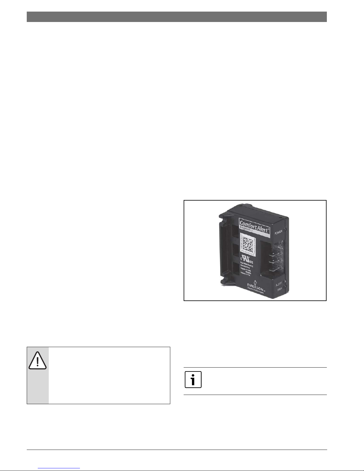
Comfort Alert Module
The Comfort Alert diagnostics module (CADM) is a
breakthrough innovation for troubleshooting heat
pump system failures. (Figure #9)
Figure # 9
By monitoring and analyzing data from the
compressor and the thermostat demand, the
module can accurately detect the cause of
electrical and system related failures without any
sensors. A flashing LED indicator communicates
the ALERT code and guides the service technician
more quickly and accurately to the root cause of a
problem.
This module does not provide safety protection!
The Comfort Alert module is a monitoring device
and cannot shut down the compressor directly.
When an abnormal system condition occurs, the
Comfort Alert module displays the appropriate
ALERT and/or TRIP LED.
The yellow ALERT LED will flash a number of times
consecutively, pause and then repeat the process.
SM CS Series Heat Pump8 733 920 846 (2013/11) Subject to change without prior notice
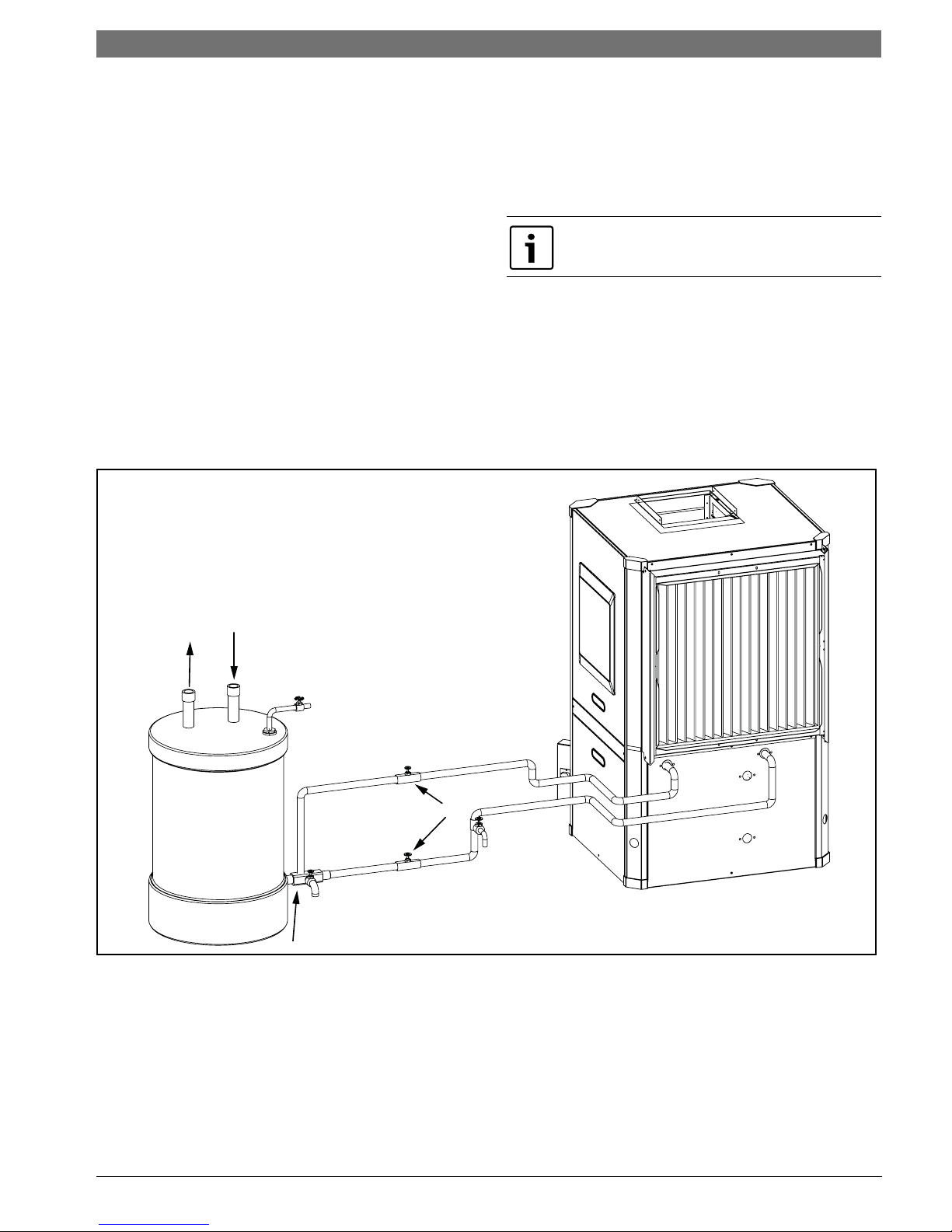
Heat Recovery Package | 11SM CS Series Heat
Hot
Water
Supply
Cold
Water
Supply
T/P Valve
Water Out
Retrun from HRP
Isolation Valves
Concentric Fitting
Part #520105
Tank Drain Valve
Water In
Supply to HRP
Drain Valve
(Optional)
NOTE: Diagram for illustration purposes only.
Ensure access to Heat Pump is not restricted.
To identify a Flash Code number, count the
number of consecutive flashes.
Every time the module powers up, the last ALERT
Flash Code that occurred prior to shut down is
displayed for one minute.Heat Recovery Package
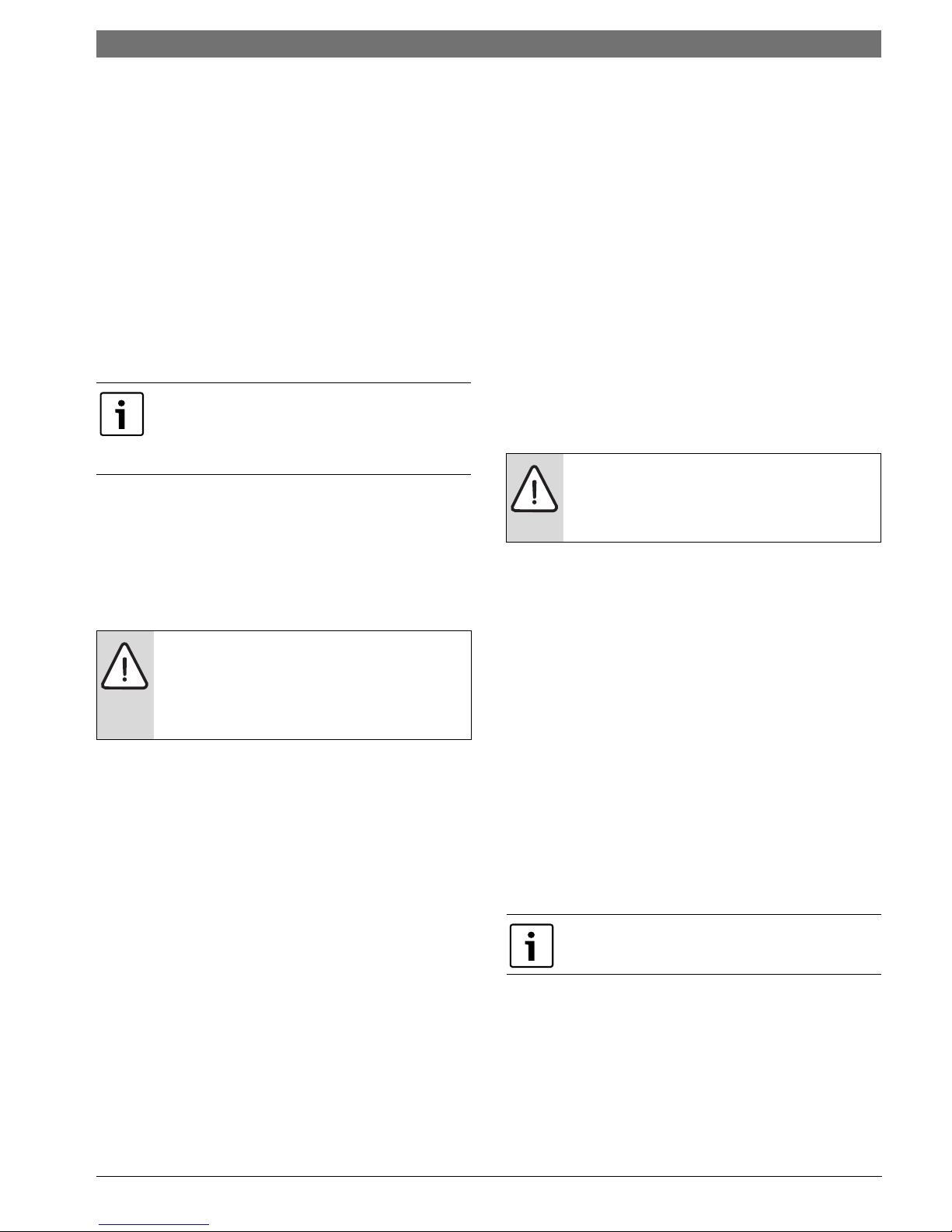
HEAT RECOVERY PACKAGE
Water Tank Preparation
1. Turn off electrical or fuel supply to the water
heater.
2. Attach garden hose to water tank drain
connection and run other end of hose out
doors or to an open drain.
3. Close cold water inlet valve to water heater
tank.
4. Drain tank by opening drain valve on the
bottom of the tank, then open pressure relief
valve or hot water faucet.
5. Once drained the tank should be flushed with
cold water until the water leaving the drain
hose is clear and free of sediment.
6. Close all valves and remove the drain hose.
7. Install HR water piping.
Concentric water fitting (p/n 520-105) is
recommended.
HR Water Piping
All hot water piping MUST be a minimum of 3/8t
O.D. copper tube to a maximum distance of fifteen
(15) feet. For distances beyond fifteen feet but not
exceeding sixty (60) feet use 1/2” copper tube.
Separately insulate all exposed surface of both
connecting water lines with 3/8” wall closed cell
insulation. Install isolation valves on supply and
return to the heat recovery. (Figure #10)
Figure # 10
8 733 920 846 (2013/11)Revised 11-13
12 | Heat Recovery Package SM CS Series Heat Pump
Water Tank Refill
1. Open the cold water supply to the tank.
2. Open a hot water faucet to vent air from the
system until water flows from the faucet, then
close.
3. Depress the hot water tank pressure relief
valve handle to ensure there is no air remaining
in the tank.
4. Carefully inspect all plumbing for water leaks.
Correct as required.
5. Purge all air from HR by depressing the
schrader valve on the HR Unit. Allow all air to
bleed out until water appears at the valve.
All piping from HRP to domestic water tank
must be copper or any metal of stronger
alloy.
6. Before restoring the power or fuel supply to
the water heater, adjust the temperature
setting on the tank thermostat(s) to ensure
maximum utilization of the heat available from
the refrigeration system and conserve the most
energy. On tanks with both upper and lower
elements and thermostats, the lower element
should be turned down to 100° F, while the
upper element should be adjusted to 120° F.
Depending upon the specific needs of the
customer, you may need to adjust the upper
element differently. On tanks with a single
thermostat lower the thermostat setting to
120° F or the “LOW” position. After thermostat
adjustments are completed, replace access
cover and restore electrical or fuel supply to
water heater.
Initial Start-Up
Make sure all valves in heat recovery water
piping system are open. NEVER OPERATE
HR PUMP DRY.
1. Turn on the heat pump. The HR pump should
not run if the compressor is not running.
2. Turn HR switch to the “ON” position. The pump
will operate if entering water temperature to
HR is below 120° F.
3. The temperature difference between the water
entering and leaving the heat recovery should
be 5° to 15° F.
4. Allow the unit to operate for 20 to 30 minutes
to ensure it is functioning properly. The pump
should shut off when the water temperature
entering the heat recovery reaches 120°F.
SM CS Series Heat Pump8 733 920 846 (2013/11) Subject to change without prior notice
Sequence of Operation | 13SM CS Series Heat
SEQUENCE OF OPERATION
Cooling Mode
Energizing the “O” terminal energizes the unit
reversing valve thus placing the unit into cooling
mode. The fan motor starts when the “G” terminal
is energized.
The fan motor will take 30 seconds to ramp up
to operating speed and will run at fan only rated
air flow as long as there is no call for compressor
or heater operation.
When the thermostat calls for first stage cooling
(Y1) the loop pump or solenoid valve if present is
energized and the first stage of compressor
capacity starts. The fan ramps up to first stage
cooling air flow in 30 seconds.
Some options will have a built in delay, and
hence, compressor operation is not immediate.
See ‘Options’ sections for more detail.
When the thermostat calls for second stage
cooling (Y2) the second stage (or full compressor
capacity) is initiated. The fan ramps up to full
cooling air flow.
Once the thermostat is satisfied, the compressor
shuts down and the fan ramps down to either fan
only mode or off over a span of 30 seconds.
Heating Mode
The first two stages of heating (Y1 & Y2) operate in
the same manner as cooling, but with the reversing
valve de-energized. On a call for auxiliary heat
(W1), the fan ramps up to auxiliary heat air flow
immediately and the electric heater package is
energized along with the compressor.
As the thermostat is satisfied, the heaters will shut
off as soon as W1 is de-energized, and the
compressors will remain on until the thermostat
stages are satisfied.
If the unit compressor locks out for any reason
at this time, the electric heaters will continue to
function normally.
Once the thermostat is satisfied, the compressor
shuts down and the fan ramps down either fan only
mode or off over a span of 30 seconds. If
thermostat has two different output points one for
Auxiliary heat and a different one for Emergency
heat the two outputs must be terminated on W1
units equipped with one stage of Electric heat.
(Figure #11)
When using a 2-cool, 3-heat thermostat both the
W1 & W2 on the Heat Pump and W2 & EM on
the thermostat must be connected together via
a jumper. (See Figure#107)
Note that a fault condition initiating a lockout will
de-energize the compressor irrespective of
which stage is engaged.
8 733 920 846 (2013/11)Revised 11-13
 Loading...