

Bosch SHX99A15UC/19, SHV99A13UC/19 Installation Guide
YOUR LIFE. OUR iNSPiRATiON.
Dishwasher lnstaJiation instructions
Lave-vaisselle Mnstructions d'instaHation
Lavadora de Platos Instrucciones de instalaci6n
P/N 9000039259(8408)
Tabmeof Contents / important instructions
mMPORTANT mNSTRUCTmONS
WARNmNG - OBSERVE ALL WARNmNGS AND CAUTmONS
These instructions are intended for use by qualified installers on{y.
Hnaddition to these instructions, the dishwasher shah be
instaHHed:
* Hnaccordance with aHHHocaHcodes or, in the absence
of a HocaHcode,
* Hnthe United States, with the NationaHEHectricCode,
* HnCanada, with the Canadian EHectricCode C22,1 -
Hatestedition/ProvinciaH and MunicipaHcodes and/or
HocaHcodes,
Read these installation instructions compJetely and
follow them carefully. They wiHHsave you time and effort
and heHpto ensure safety and optimum dishwasher
CAUTION: nfthe dishwasher is instaHHedin a Hocation
that experiences freezing temperatures (e,g,, in a hoHiday
home), you must drain aHHthe water from the dishwash-
er's interior, Water system ruptures that occur as a resuHt
of freezing are not covered by warranty,
IMPORTANT
*The dishwasher drain hose must be instaHHedwith a
portion of it at Heast20" (508mm) off the cabinet floor;
otherwise the dishwasher may not drain properly,
*This dishwasher is intended for residentiaH use onHy,and
shouHdnot be used in commerciaH food service
estabHishments,
*NEW INSTALLATION - Hfthe dishwasher is a new
instaHHation,most of the work must be done before the
dishwasher is moved into pHace,
*REPLACEMENT -Hfthe dishwasher is repHacinganother
dishwasher, check the existing dishwasher connections
for compatibiHity with the new dishwasher, and repHace
parts as necessary,
Inspect the Dishwasher
After unpacking the dishwasher and prior to instaHHation,
thoroughHy inspect the dishwasher for possibHefreight or
cosmetic damage, Report any damage immediateHy,
Cosmetic defects must be reported within 5days of
instaHHation,
NOTE: Do not discard any bags or items that come with
the originaHpackage untiHafter the entire instaHHationhas
been compHeted,
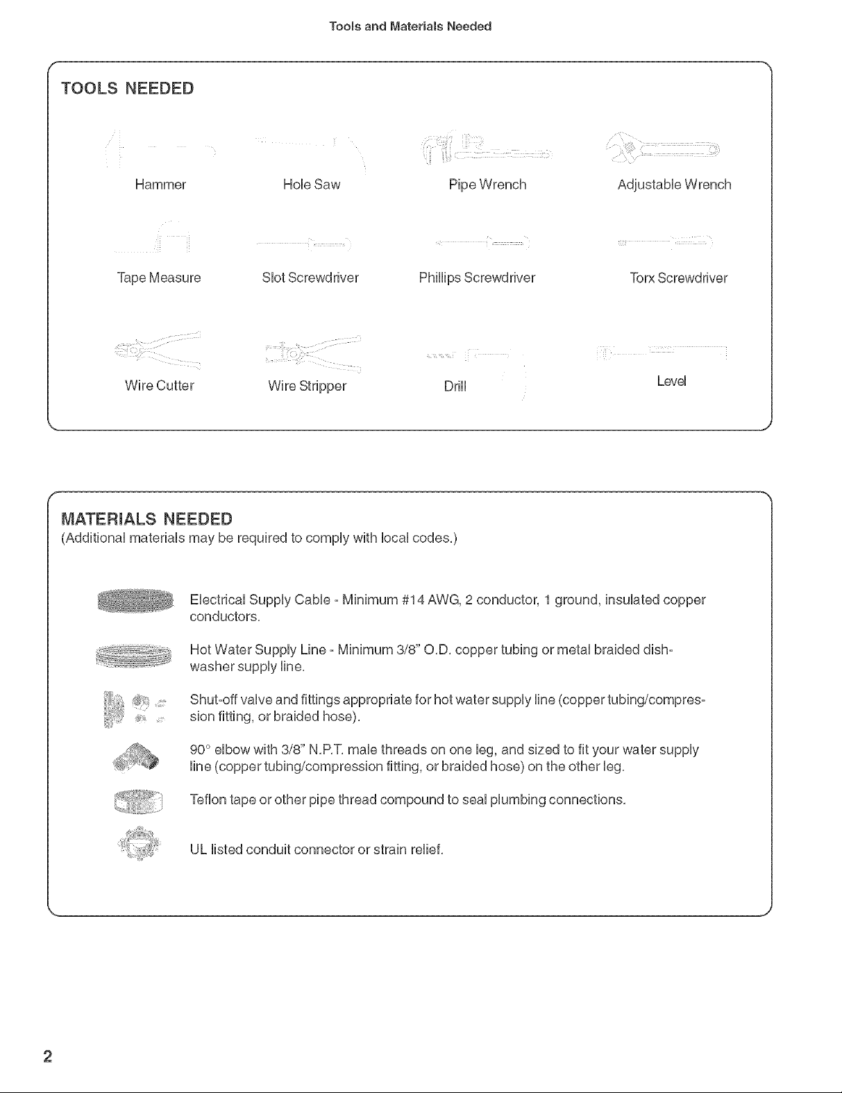
TOOLS NEEDED
Hammer
]roomsand Mater}a(s Needed
Tape Measure
Wire Cutter
SUotScrewdriver
Wire Stripper DrHU
PhHHpsScrewdriver
MATERIALS NEEDED
(AdditionaU materiaUs may be required to compUywith bcaU codes,)
EUectricaUSuppUyCaNe - Minimum #14 AWG, 2 conductor, 1 ground, insuUatedcopper
conductors,
!::_,_-_, Hot Water SuppUyLine - Minimum 3/8" O.D. copper tubing or metal braided dish-
washer supply line.
Torx Screwdriver
LeveU
Shut-off valve and fittings appropriate for hot water supply line (copper tubing/compres-
_,, sion fitting, or braided hose).
.... _ line (copper tubing/compression fitting, or braided hose) on the other leg.
90° elbow with 3/8" N.P.T. male threads on one leg, and sized to fit your water supply
Teflon tape or other pipe thread compound to seal plumbing connections.
UL listed conduit connector or strain relief.
2
@
®
Matertals
Supplied
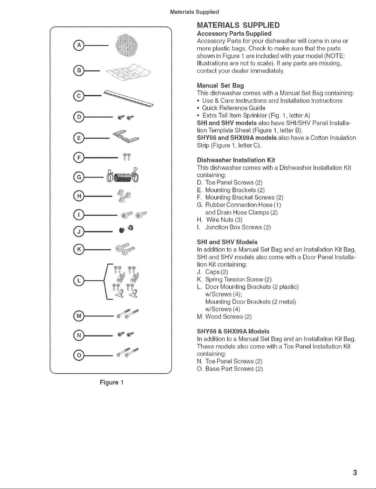
MATERIALS SUPPUED
Accessory Parts Supplied
Accessory Parts for your dishwasher wHUcome in one or
more pUastb bags, Check to make sure that the parts
shown in Figure 1 are included with your modeU(NOTE:
HUustrationsare not to scab), if any parts are missing,
contact your deabr immediateUy,
ManuaJ Set Bag
This dishwasher comes with a ManuaUSet Bag containing:
, Use & Care instructions and installation Instructions
* Quick Reference Guide
* Extra Tall Item Sprinkler (Fig, 1, btterA)
SIll and SHY modeJs also have SHI/SHV Panel Installa=
tion Template Sheet (Figure 1, letter B),
SHY66 and SHX99A models also have a Cotton Insulation
Strip (Figure 1, letter C),
®
®
®
®
®
Dishwasher Installation Kit
This dishwasher comes with a Dishwasher Installation Kit
D, Toe Panel Screws (2)
E, Mounting Brackets (2)
F, Mounting Bracket Screws (2)
G, Rubber Connection Hose (1)
and Drain Hose Clamps (2)
H, Wire Nuts (3)
I, Junction Box Screws (2)
SHI and SHV Models
In addition to a Manual Set Bag and an Installation Kit Bag,
SHI and SHV models also come with a Door Panel Installa=
tion Kit containing:
J, Caps (2)
K, Spring Tension Screw (2)
L, Door Mounting Brackets (2 plastic)
w/Screws (4);
Mounting Door Brackets (2 metal)
w/Screws (4)
M, Wood Screws (2)
SHY66 & SHX99A Models
in addition to a blanual Set Bag and an Installation Kit Bag,
These models also come with a Toe Panel Installation Kit
containing:
N, Toe Panel Screws (2)
O, Base Part Screws (2)
Figure 1
Enclosure Preparation
23-9/I6"
[598mm)
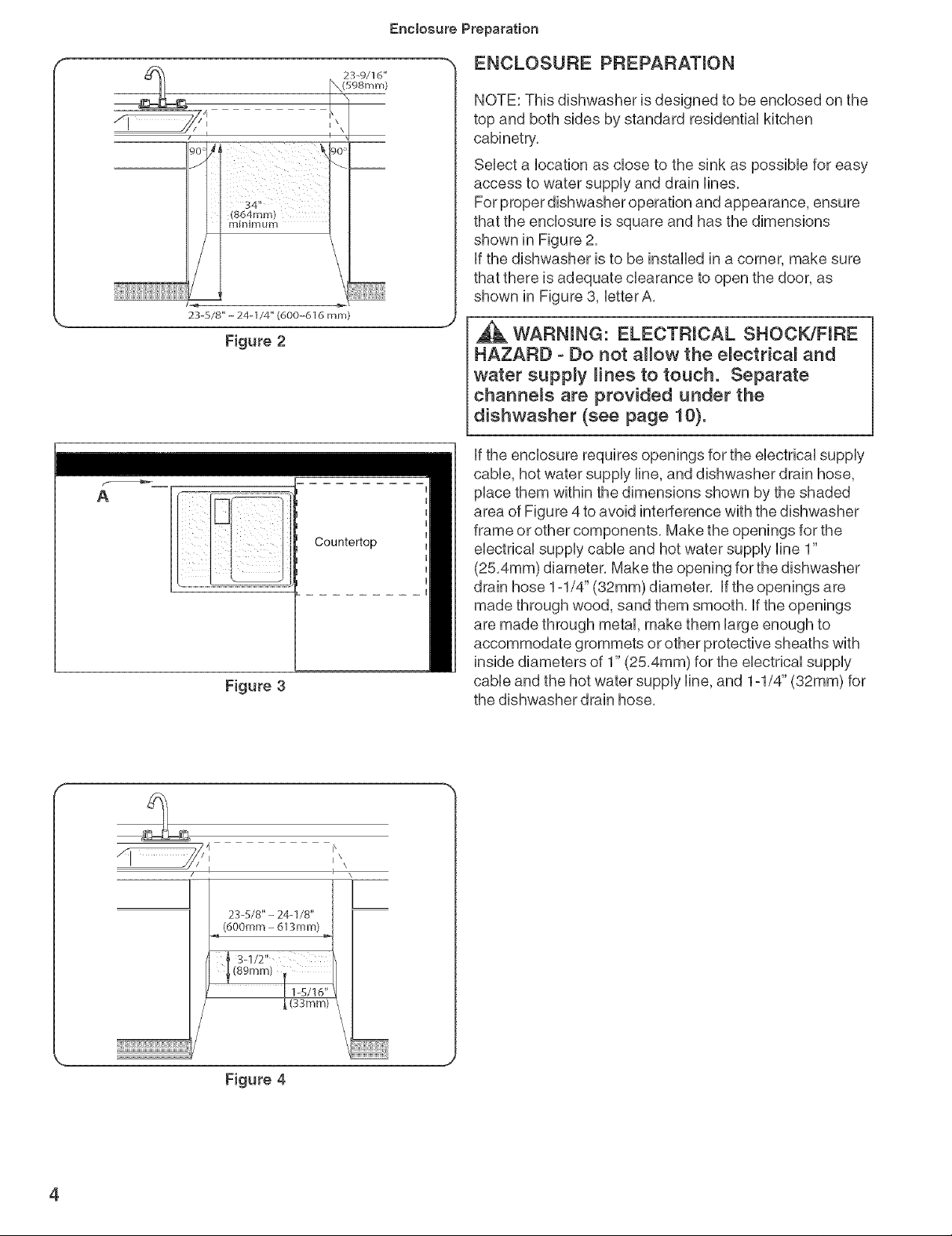
ENCLOSURE PREPARATmON
NOTE: This dishwasher is designed to be encbsed on the
top and both sides by standard residentiN kitchen
cabinetry,
Sebct a bcation as dose to the sink as possibb for easy
access to water suppUyand drain Hnes,
For proper dishwasher operation and appearance, ensure
that the encbsure is square and has the dimensions
shown in Figure 2,
if the dishwasher is to be installed in a corner, make sure
that there is adequate clearance to open the door, as
shown in Figure 8, letterA,
,_ WARNmNG: ELECTRICAL SHOCK/FIRE
HAZARD - Do not allow the e_ectricN and
water supply Hnee to touch. Separate
channels are provided under the
dishwasher (see page 10).
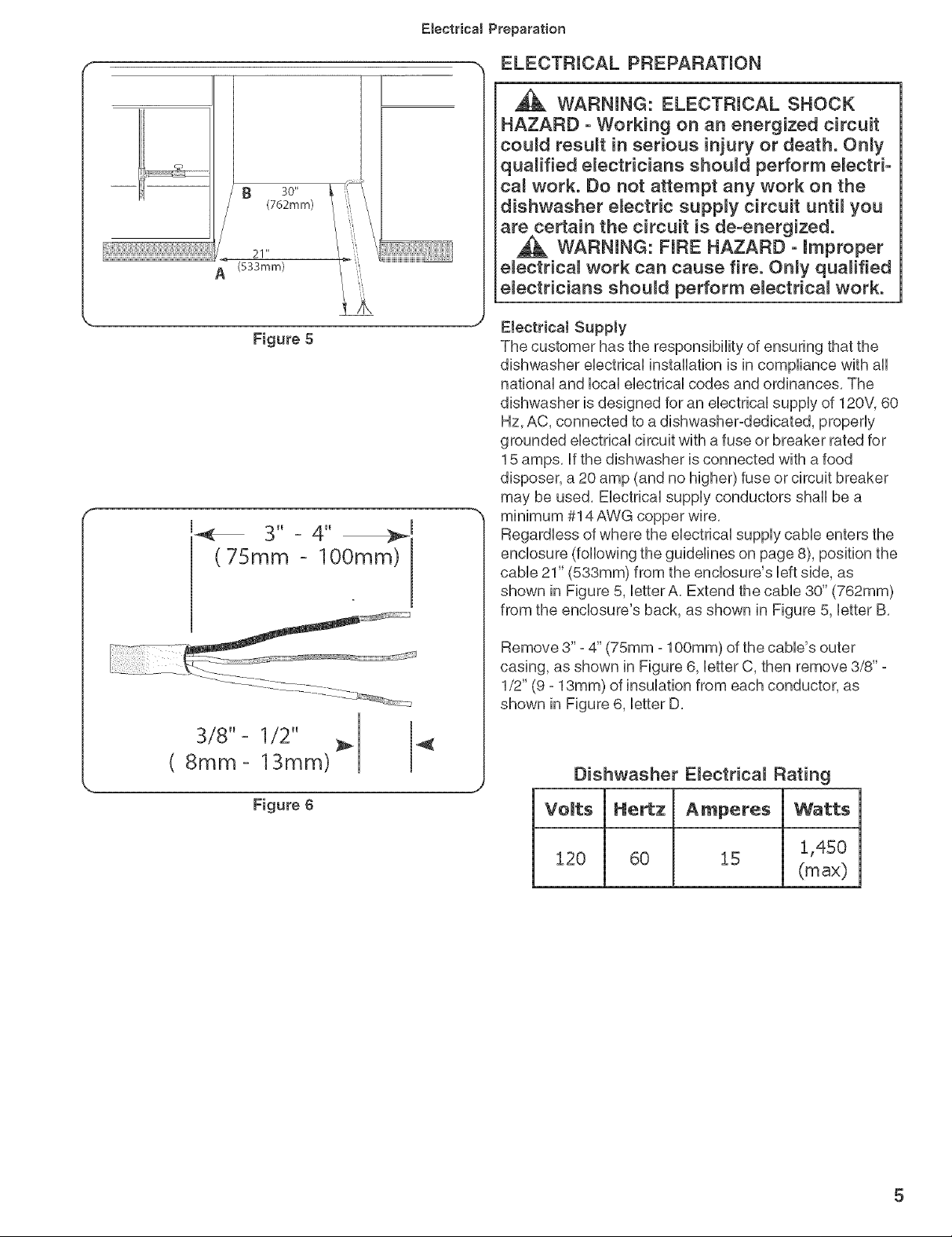
if the enclosure requires openings for the electrical supply
cable, hot water supply line, and dishwasher drain hose,
A
Countertop
Figure 3
place them within the dimensions shown by the shaded
area of Figure 4to avoid interference with the dishwasher
frame or other components, Make the openings for the
electrical supply cable and hot water supply line 1"
(25,4mm) diameter, Make the opening for the dishwasher
drain hose 1ol/4" (32mm) diameter, if the openings are
made through wood, sand them smooth, if the openings
are made through metal, make them large enough to
accommodate grommets or other protective sheaths with
inside diameters of 1" (25,4mm) for the electrical supply
cable and the hot water supply line, and 1ol/4" (32mm) for
the dishwasher drain hose,
i\
I\\
23-5/8"- 24-1/8"
(600mm - 613mm)
Figure 4
4
30"
(762mm)
21"
(533mm)
/X
Figure 5
(75mm lOOmm).
Electrical Preparation
. ELECTRICAL PREPARATmON
,_ WARNmNG: ELECTRICAL SHOCK
HAZARD - Working on an energized circuit
could recur in serious injury or death. Only
qualified electricians should perform electrb
cal work. Do not attempt any work on the
dishwasher electric supply circuit until you
are certain the circuit is de-energized.
,_ WARNING: FiRE HAZARD - improper
emectrical work can cause fire. Only qualified
e_ectricians should perform e_ectrica_ work.
ElectricaJ Supply
The customer has the responsibility of ensuring that the
dishwasher electrical installation is in compliance with all
national and local electrical codes and ordinances, The
dishwasher is designed for an electrical supply of 120V, 60
Hz, AC, connected to a dishwasher-dedicated, properly
grounded electrical circuit with a fuse or breaker rated for
15 amps, if the dishwasher is connected with a food
disposer, a 20 amp (and no higher) fuse orcircuit breaker
may be used, Electrical supply conductors shall be a
minimum #14 AWG copper wire,
Regardless of where the electrical supply cable enters the
enclosure (following the guidelines on page 8), position the
cable 21" (533mm) from the enclosure's left side, as
shown in Figure 5, letter A, Extend the cable 30" (762mm)
from the enclosure's back, as shown in Figure 5, letter B,
3/8" - 1/2" 4{
(8ram- 13ram)
Figure 6
Remove 3" - 4" (75mm -100mm) of the cable's outer
casing, as shown in Figure 6, letter C, then remove 3/8" -
1/2" (9 - 13mm) of insulation from each conductor, as
shown in Figure 6, letter D,
Dishwasher E_ectrical Rating
Volts Amperes Watts
120 60 15 1,450
(max)
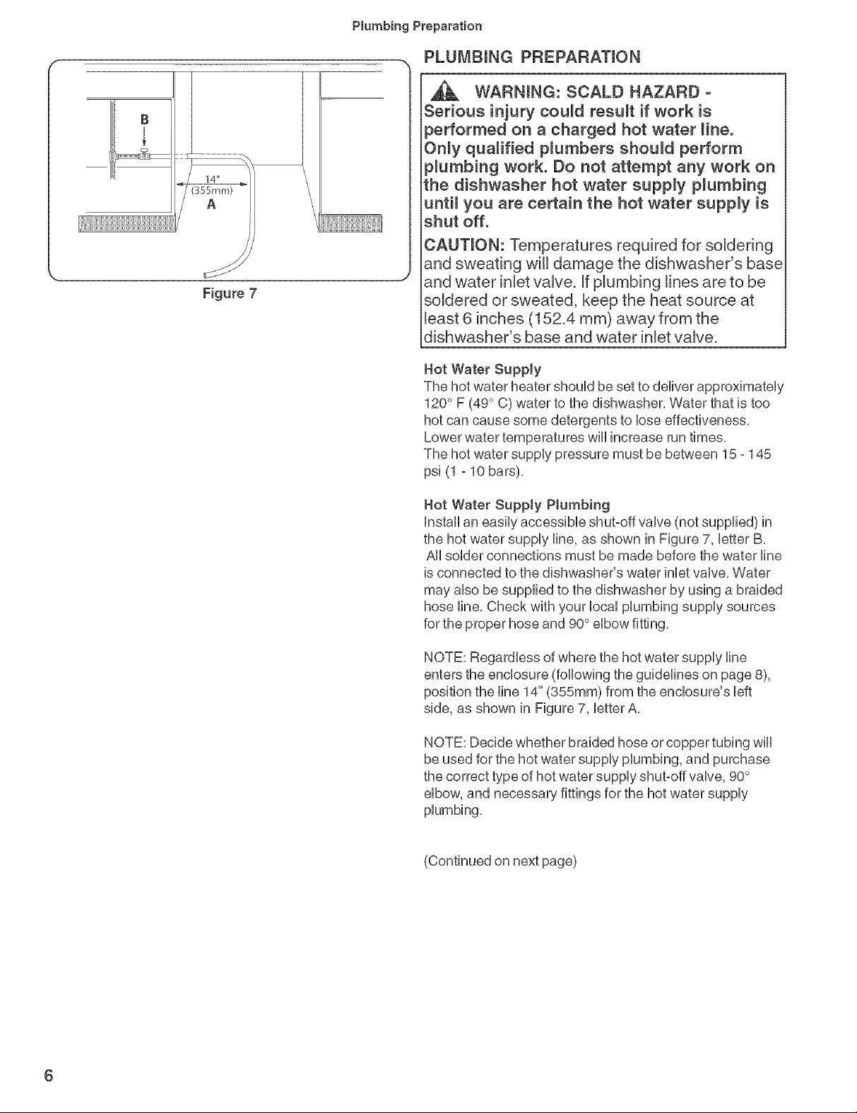
Figure 7
PBumbingPreparation
PLUMBING PREPARATmON
WARNmNG: SCALD HAZARD -
Serious injury could result if work is
performed on a charged hot water Hne.
Only qualified p_umbers should perform
p_umbing work. Do not attempt any work on
the dishwasher hot water supply p_umbing
unti_ you are certain the hot water supply is
shut off.
CAUTION: Temperatures required for soldering
and sweating will damage the dishwasher's base
and water inlet valve. If plumbing lines are to be
soldered or sweated, keep the heat source at
least 6 inches (152.4 ram) away from the
dishwasher's base and water inlet valve.
Hot Water Supply
The hot water heater shouUdbe set to deliver approximateUy
120° F (49° C) water to the dishwasher, Water that is too
hot can cause some detergents to lose effectiveness,
Lower water temperatures will increase run times,
The hot water supply pressure must be between 15 - 145
psi (1 - 10 bars),
Hot Water Supply PJumbing
Install an easily accessible shut-off valve (not supplied) in
the hot water supply line, as shown in Figure 7, letter B,
All solder connections must be made before the water line
is connected to the dishwasher's water inlet valve, Water
may also be supplied to the dishwasher by using a braided
hose line, Check with your local plumbing supply sources
for the proper hose and 90° elbow fitting,
NOTE: Regardless of where the hot water supply line
enters the enclosure (following the guidelines on page 8),
position the line 14" (355mm) from the enclosure's left
side, as shown in Figure 7, letter A,
NOTE: Decide whether braided hose or copper tubing wiii
be used for the hot water supply plumbing, and purchase
the correct type of hot water supply shut-off valve, 90°
elbow, and necessary fittings for the hot water supply
(Continued on next page)
6
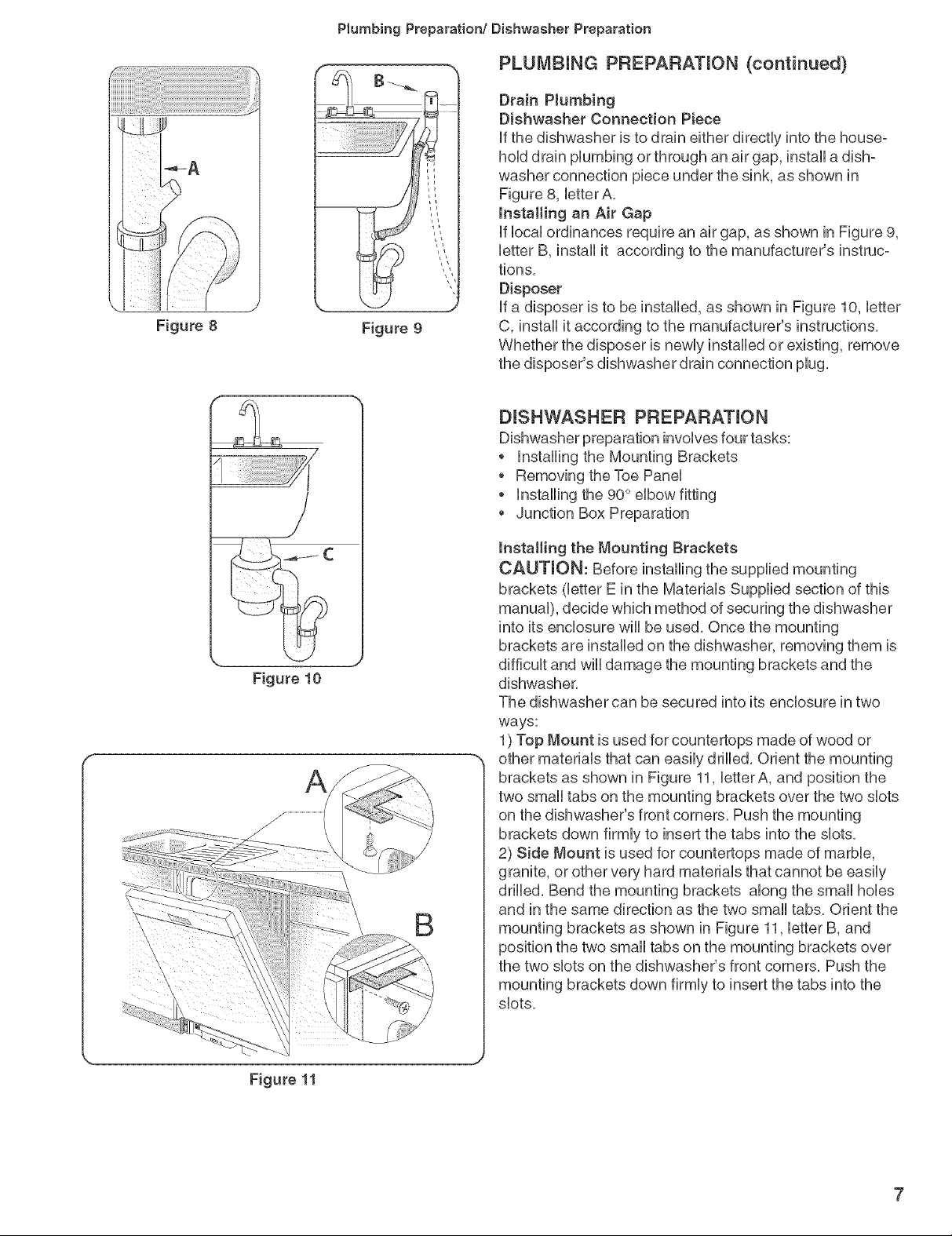
Figure 8
Plumbing Preparation/Dishwasher Preparation
r %
Figure 9
PLUMBING PREPARATION (continued)
Drain PJumbing
Dishwasher Connection Piece
If the dishwasher is to drain either directly into the house°
hold drain plumbing or through an air gap, install a dish-
washer connection piece under the sink, as shown in
Figure 8, letter A,
Installing an Air Gap
If local ordinances require an air gap, as shown in Figure 9,
letter B, install it according to the manufacturer's instruc-
tions,
Disposer
If a disposer is to be installed, as shown in Figure 10, letter
C, install it according to the manufacturer's instructions,
Whether the disposer is newly installed or existing, remove
the disposer's dishwasher drain connection plug,
DISHWASHER PREPARATmON
Dishwasher preparation involves four tasks:
o Installing the Mounting Brackets
o Removing the Toe Panel
o Installing the 90° elbow fitting
Junction Box Preparation
Figure 10
B
lnstaHing the Mounting Brackets
CAUTION: Before installing the supplied mounting
brackets (letter E in the Materials Supplied section of this
manual), decide which method of securing the dishwasher
into its enclosure will be used, Once the mounting
brackets are installed on the dishwasher, removing them is
difficult and will damage the mounting brackets and the
dishwasher,
The dishwasher can be secured into its enclosure in two
ways:
1) Top Mount is used for countertops made of wood or
other materials that can easily drilled, Orient the mounting
brackets as shown in Figure 11, letterA, and position the
two small tabs on the mounting brackets over the two slots
on the dishwasher's front corners, Push the mounting
brackets down firmly to insert the tabs into the slots,
2) Side Mount is used for countertops made of marble,
granite, or other very hard materials that cannot be easily
drilled, Bend the mounting brackets along the small holes
and in the same direction as the two small tabs, Orient the
mounting brackets as shown in Figure 11, letter B, and
position the two small tabs on the mounting brackets over
\
the two slots on the dishwasher's front corners, Push the
mounting brackets down firmly to insert the tabs into the
slots,
Figure 11
DishwasherPreparation
DmSHWASHER PREPARATmON (continued)
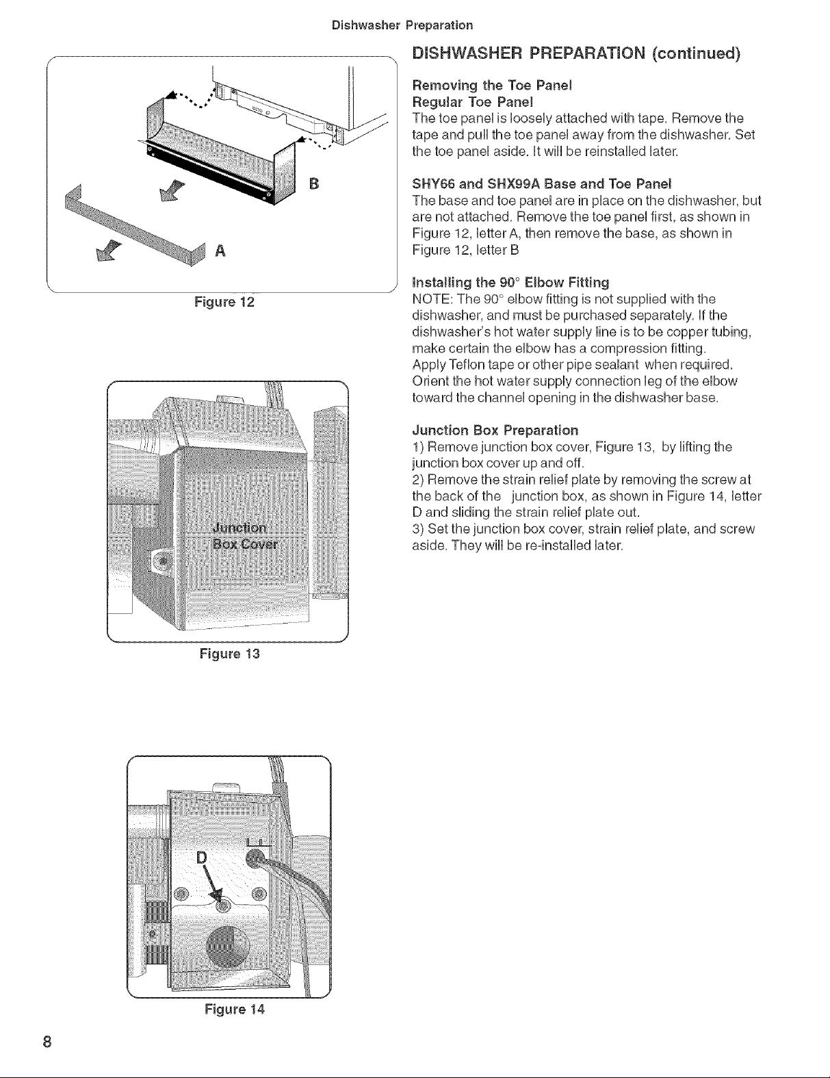
Removing the Toe Pane1
Regular Toe Pane!
The toe paneHis HooseHyattached with tape, Remove the
tape and puHHthe toe paneHaway from the dishwasher, Set
the toe paneHaside, HtwHHbe reinstaHHedHater,
SHY66 and SHX99A Base and Toe PaneJ
The base and toe paneHare in pHaceon the dishwasher, but
are not attached, Remove the toe paneHfirst, as shown in
Figure 12, HetterA, then remove the base, as shown in
Figure 12, HetterB
installing the 90° Elbow Fitting
NOTE: The 90° eHbowfitting is not supplied with the
dishwasher, and must be purchased separateHy,Hfthe
dishwasher's hot water suppHyHineis to be copper tubing,
make certain the eHbowhas a compression fitting,
AppHyTeflon tape or other pipe seaHant when required,
Orient the hot water suppHyconnection Hegof the eHbow
toward the channeHopening in the dishwasher base,
Figure13
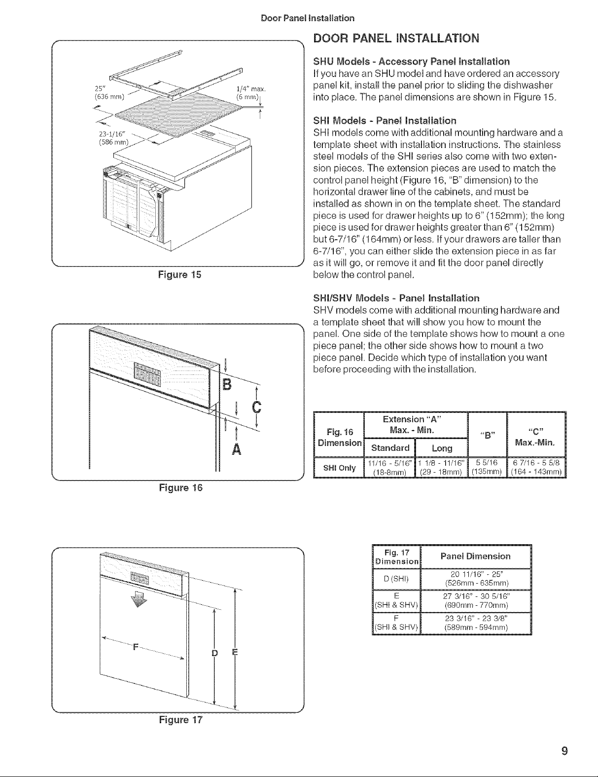
Junction Box Preparation
1) Remove junction box cover, Figure 13, by Hiftingthe
junction box cover up and off,
2) Remove the strain reHiefpilate by removing the screw at
the back of the junction box, as shown in Figure 14, Hetter
D and sHidingthe strain reHiefpilateout,
3) Set the junction box cover, strain reHiefpilate, and screw
aside, They wiHHbe re-instaHHedHater,
Figuce14
8
25 _
(636 mm)
23-1/16"
(586 mm)
Figure 15
Door Panet Installation
DOOR PANEL INSTALLATION
SHU ModeJs - Accessory Panet Installation
Ufyou have an SHU modeUand have ordered an accessory
paneUkit, install the paneUprior to sliding the dishwasher
into pUace,The paneUdimensions are shown in Figure 15,
SIll Models - PaneJ Installation
SHUmodeUscome with additionaU mounting hardware and a
tempUate sheet with installation instructions, The stainUess
steeUmodels of the SHI series also come with two exten-
sion pieces, The extension pieces are used to match the
control panel height (Figure 16, "B" dimension) to the
horizontal drawer line of the cabinets, and must be
installed as shown in on the template sheet, The standard
piece is used for drawer heights up to 6" (152mm); the long
piece is used for drawer heights greater than 6" (152mm)
but 6-7/16" (164mm) or less, If your drawers are taller than
6-7/16", you can either slide the extension piece in as far
as it will go, or remove it and fit the door panel directly
below the control panel,
SIll/SHY Models - PaneJ Installation
SHV models come with additional mounting hardware and
a template sheet that will show you how to mount the
panel, One side of the template shows how to mount a one
piece panel; the other side shows how to mount a two
piece panel, Decide which type of installation you want
before proceeding with the installation,
C
A
k. j
Figure 16
Fig. 16
Dimension
SHI Only
Extension "A"
Max. _ Min.
Standard Long
11/16-5/16" 1 !/8-1!/16" 55/16 67/16-55/8
/18-Smrn) (29- 18ram) (!35mm) (164- 143turn)
Fig. 17 Panel Dimension
Dimension
D (SHI) (526mrn - 635mrn)
E 27 3/16" - 30 5/16"
SHI & SHV (690mm - 770mm)
F 23 3/16" - 23 3/8"
SIll & SHV) (589mm - 594mm)
"B" "C"
Maxo-Min,
20 11/16" - 25"
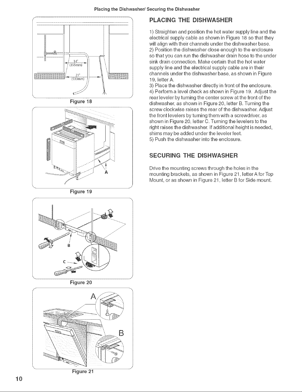
Figure 18
Placing the Dishwasher/Securing the Dishwasher
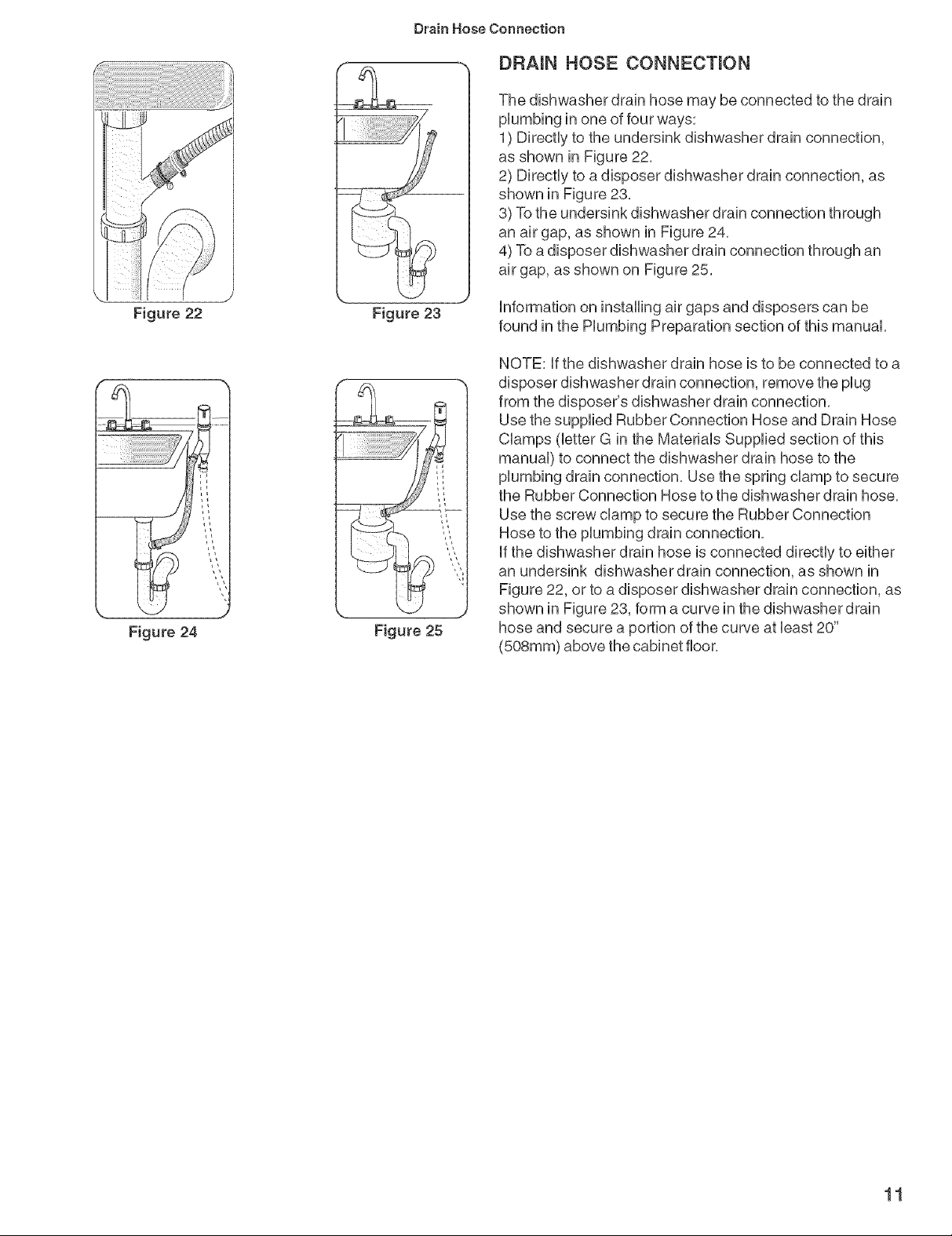
PLACmNG THE DISHWASHER
1) Straighten and position the hot water supply line and the
electrical supply cable as shown in Figure 18 so that they
will align with their channels under the dishwasher base,
2) Position the dishwasher close enough to the enclosure
so that you can run the dishwasher drain hose to the under
sink drain connection, Make certain that the hot water
supply line and the electrical supply cable are in their
channels under the dishwasher base, as shown in Figure
19, letter A,
3) Place the dishwasher directly in front of the enclosure,
4) Perform a level check as shown in Figure 19, Adjust the
rear leveler by turning the center screw at the front of the
dishwasher, as shown in Figure 20, letter B, Turning the
screw clockwise raises the rear of the dishwasher, Adjust
the front levelers by turning them with a screwdriver, as
shown in Figure 20, letter C, Turning the levelers to the
right raises the dishwasher, if additional height is needed,
shims may be added under the leveler feet,
5) Push the dishwasher into the enclosure,
SECURING THE DmSHWASHER
A
Figure 19
Figure 20
f
Drive the mounting screws through the hoUesin the
mounting brackets, as shown in Figure 21, UetterAfor Top
Mount, or as shown in Figure 21, UetterB for Side mount.
A
10
Figure 21
Drain Hose Connection
DRAmN HOSE CONNECTmON
The dishwasher drain hose may be connected to the drain
plumbing in one of four ways:
1) Directly to the undersink dishwasher drain connection,
as shown in Figure 22,
2) Directly to a disposer dishwasher drain connection, as
shown in Figure 28,
3) To the undersink dishwasher drain connection through
an air gap, as shown in Figure 24,
4) To a disposer dishwasher drain connection through an
air gap, as shown on Figure 25,
Figure22
Figure24
Figure 23
Figure 25
information on installing air gaps and disposers can be
found in the Plumbing Preparation section of this manual,
NOTE: if the dishwasher drain hose is to be connected to a
disposer dishwasher drain connection, remove the plug
from the disposer's dishwasher drain connection,
Use the supplied Rubber Connection Hose and Drain Hose
Clamps (letter G in the Materials Supplied section of this
manual) to connect the dishwasher drain hose to the
plumbing drain connection, Use the spring clamp to secure
the Rubber Connection Hose to the dishwasher drain hose,
Use the screw clamp to secure the Rubber Connection
Hose to the plumbing drain connection,
if the dishwasher drain hose is connected directly to either
an undersink dishwasher drain connection, as shown in
Figure 22, or to adisposer dishwasher drain connection, as
shown in Figure 23, form a curve in the dishwasher drain
hose and secure a portion of the curve at bast 20"
(508mm) above the cabinet floor,
11
Hot Water Connection
HOT WATER CONNECTmON
,_ WARNmNG: SCALD HAZARD ° Working
on a charged hot water Hne could result in
serious injury or death. Do not attempt any
work on the dishwasher hot water supply
p_umbing until you are certain the hot water
supply isshut off.
NOTE: Make certain that the correct 90° eUbowfitting (not
supplied) for the hot water suppUyHnehas been purchased
and installed on the dishwasher as described in the
Dishwasher Preparation section of this manual
The hot water suppUyHnemay be connected to the
dishwasher in one of two ways:
1) With braided hose
2) With copper tubing
Braided Hose
After connections are made turn on the hot water suppUy
to check for Ueaks,
Copper Tubing
CAUTION: Temperatures required for soldering and
sweating will damage the dishwasher's water inlet valve, if
plumbing lines are to be soldered or sweated, keep the
heat source at least 6 inches (152,4 mm) away from the
dishwasher's water inlet valve,
o if using a solder joint instead of a compression fitting,
be sure to make all solder connections before connect-
ing the water line to the dishwasher,
o Make certain there are no sharp bends or kinks in the
water line that might restrict water flow,
Be sure to use pipe thread compound or Teflon tape to
seal the connection when required,
o Before connecting the copper hot water supply line to
the dishwasher, flush it with hot water to clear any
12
Turn on the water supply to check for leaks after making
connections,
Electricam Connection
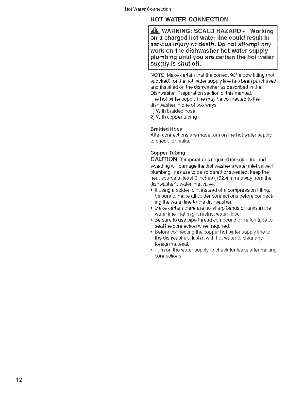
ELECTRICAL CONNECTmON
Strain
J ReJief
[
i
.... PJate
,_ WARNmNG: ELECTRICAL SHOCK
HAZARD - Working on an energized circuit
could result in serious injury or death. Only
qualified e_ectricians
shouM perform ebctrbal work. Do not
attempt any work on the dishwasher electric
supply circuit unti_ you are certain the circuit
is de-energized.
,_ WARNmNG: FIRE HAZARD -
mmproper electrica_ work can cause fire. Only
qualified e_ectricians should perform e_ectri-
ca_ work.
Grounding instructions
The dishwasher must be properly grounded before
operating, This appliance must be connected to a
grounded metal permanent wiring system, or an equipment
grounding conductor must be run with the circuit
conductors and connected to the equipment grounding
terminal or lead on the dishwasher, Make sure that the
dishwasher is connected to a suitable ground in
compliance with all local codes or, in the absence of a
local code, with the NATIONAL ELECTRICAL CODE in the
United States or the CANADIAN ELECTRIC CODE C22,1 -
latest edition in Canada as well as any provinciaVstate or
municipal or local codes that apply,
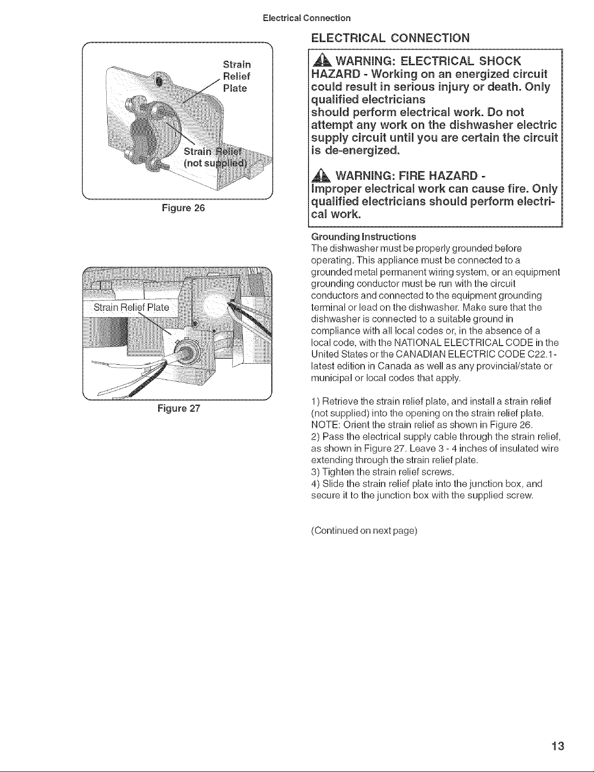
Figure 27
1) Retrieve the strain relief plate, and install a strain relief
(not supplied) into the opening on the strain relief plate,
NOTE: Orient the strain relief as shown in Figure 26,
2) Pass the electrical supply cable through the strain relief,
as shown in Figure 27, Leave 3 - 4 inches of insulated wire
extending through the strain relief plate,
3) Tighten the strain relief screws,
4) Slide the strain relief plate into the junction box, and
secure it to the junction box with the supplied screw,
(Continued on next page)
13
Emectricam Connection/Door Tension Adjustment/Base and Toe Panet
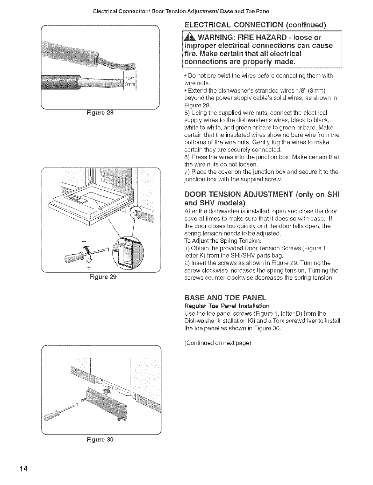
-_ ELECTRICAL CONNECTmON (continued)
* Do not pre-twist the wires before connecting them with
wire nuts,
* Extend the dishwasher's stranded wires 1/8" (3mm)
beyond the power suppUycaMe's solid wires, as shown in
Figure 28,
5) Using the supplied wire nuts, connect the eUectricaU
suppUywires to the dishwasher's wires, bUackto bUack,
white to white, and green or bare to green or bare, Make
certain that the insuUatedwires show no bare wire from the
bottoms of the wire nuts, GentUytug the wires to make
certain they are secureUyconnected,
6) Press the wires into the junction box, Make certain that
the wire nuts do not loosen,
7) Place the cover on the junction box and secure it to the
junction box with the supplied screw,
Figure 29
DOOR TENSION ADJUSTMENT (only on Sill
and SHV models)
After the dishwasher is installed, open and close the door
several times to make sure that it does so with ease, If
the door closes too quickly or if the door falls open, the
spring tension needs to be adjusted,
ToAdjust the Spring Tension:
1) Obtain the provided Door Tension Screws (Figure 1,
letter K) from the SHI/SHV parts bag,
2) Insert the screws as shown in Figure 29, Turning the
screw clockwise increases the spring tension, Turning the
screws counter-clockwise decreases the spring tension,
BASE AND TOE PANEL
ReguJar Toe Panel installation
Use the toe panel screws (Figure 1, letter D) from the
Dishwasher Installation Kit and a Torx screwdriver to install
the toe panel as shown in Figure 30,
14
Figure 30
 Loading...