

Bosch SHE4AM12U, SHE4AM02UC, SHE5AM02UC, SHX3AM02UC Repair Instructions

A
A
A
S
S
S
C
C
C
E
E
E
N
N
N
T
T
T
A
A
A
D
D
D
W
W
W
R
R
R
E
E
E
P
P
P
A
A
A
I
I
I
R
R
R
I
I
I
N
N
N
S
S
S
T
T
T
R
R
R
U
U
U
C
C
C
T
T
T
I
I
I
O
O
O
N
N
N
1 SAFETY.................................................. 3
4.7 Water inlet / condensation system...........................14
4.8 Door spring.................................................................15
1.1 General hazards...........................................................3
4.9 Terminal box...............................................................15
1.2 Electrical shock / fire hazards.....................................3
4.10 Aqua sensor ...............................................................16
1.3 Plumbing / scalding hazards.......................................3
4.11 Drain hose ..................................................................16
2 INSTALLATION...................................... 4
4.12 Sump parts .................................................................17
4.13 Tank with base and sump .........................................18
2.1 Pre-Install checklist .....................................................4
4.14 Serial label (warranty information)...........................19
2.2 Alignment .....................................................................4
5 REPAIR................................................. 20
2.3 Electrical connection...................................................4
2.4 Water connection.........................................................5
5.1 Access ........................................................................20
2.5 Drain and condensation hose connections...............5
5.2 Controls......................................................................24
3 OPERATION........................................... 6
5.3 Dispensers..................................................................27
5.4 Door latches ...............................................................28
3.1 Control layout...............................................................6
5.5 Water valves...............................................................29
3.2 Using controls..............................................................6
5.6 Drain pumps...............................................................30
3.3 Reset (“Cancel – drain”)..............................................6
5.7 Water inlet & condensation tube ..............................30
3.4 Changing basic settings..............................................6
5.8 Sump parts .................................................................31
3.5 Special programs (codings)........................................ 8
5.9 Inner doors .................................................................32
3.6 Sales demo (showroom) program..............................9
5.10 Door hinge levers.......................................................32
4 COMPONENTS..................................... 10
5.11 Lower door seals........................................................33
4.1 Control and power modules......................................10
5.12 Heat pump disassembly............................................33
4.2 Door latch...................................................................10
5.13 Float (safety system) .................................................34
4.3 Dispenser....................................................................11
5.14 2-piece drain hose connection .................................35
4.4 Heat pump ..................................................................12
6 FAULT DIAGNOSTICS......................... 36
4.5 Drain pump.................................................................13
6.1 Error codes (service / customer)..............................36
4.6 Float ............................................................................14
702_58300000130262_ara_en_c Page 1 of 50

6.2 Customer service test program................................41
6.3 Troubleshooting.........................................................43
7 TECHNICAL SPECIFICATIONS .......... 50
702_58300000130262_ara_en_c Page 2 of 50

1 SAFETY
1.1 General hazards
Don’t use the dishwasher until it is completely installed. When
opening the door on an uninstalled dishwasher, carefully open
the door while supporting the rear of the unit. Failure to follow this
warning can cause the dishwasher to tip over and result in
serious injury.
In some conditions, hydrogen gas can form in a hot water system
that has not been used for weeks. Hydrogen gas is explosive.
Before filling a dishwasher from a system that has been off for
weeks, run the water from a nearby faucet in a well ventilated
area until there is no sound or evidence of gas.
Temperatures required for soldering and sweating will damage
the dishwasher’s base and water inlet valve. If plumbing lines are
to be soldered or sweated, keep the heat source at least 6 inches
(152.4 mm) away from the dishwasher’s base and water inlet
valve.
Removing any cover or pulling the dishwasher from the cabinet
can expose hot water connections, electrical power and sharp
edges or points. Handle with care. Always wear gloves and safety
glasses.
1.2 Electrical shock / fire hazards
Don’t allow electrical and water supply lines to touch. Don’t work
on an energized circuit. Doing so could result in serious injury or
death. Only qualified electricians should perform electrical work.
Don’t attempt any work on the dishwasher electric supply circuit
until you are certain the circuit is de-energized.
Make sure electrical work is properly installed. There should be
no loose electrical connections. Ensure all electrical connections
are properly made.
The customer has the responsibility of ensuring that the
dishwasher electrical installation is in compliance with all national
and local electrical codes and ordinances. The dishwasher is
designed for an electrical supply of 120VAC, 60 Hz, connected to
a dishwasher-dedicated, properly grounded electrical circuit with
a fuse or breaker rated for 15 amps. Electrical supply conductors
shall be a minimum #14 AWG copper only wire rated at 75°C
(167°F) or higher.
m
This appliance must be connected to a grounded metal,
permanent wiring system, or an equipment-grounding conductor
must be run with the circuit conductors and connected to the
equipment-grounding terminal or lead on the appliance. Don’t use
extension cords.
1.3 Plumbing / scalding hazards
m
Don’t perform any work on a charged hot water line. Serious
injury could result. Only qualified plumbers should perform
plumbing work. Don’t attempt any work on the dishwasher hot
water supply plumbing until you are certain the hot water supply
is shut off.
Don’t over tighten the 90° elbow. Doing so may damage the
water inlet valve and cause a water leak. Temperatures required
for soldering and sweating will damage the dishwasher’s water
inlet valve. If plumbing lines are to be soldered or sweated, keep
the heat source at least 6 inches (152.4 mm) away from the
dishwasher’s water inlet valve.
c h
Check local plumbing codes for approved plumbing procedures
and accessories. All plumbing should be done in accordance with
national and local codes.
These instructions depict an installation method for stainless steel
braided hose or PEX hot water supply lines. If using copper
tubing or other material for water supply, defer to a licensed
plumber for proper installation.
702_58300000130262_ara_en_c Page 3 of 50
2 INSTALLATION
2.1 Pre-Install checklist
□ Unpack unit. Retain packing material until installation is
successful. Remove packing material from inside the
dishwasher.
□ Inspect parts to ensure you have all the necessary materials.
□ Flush household hot water supply for at least two minutes.
□ Measure the enclosure area. The opening must be at least
34" (87 cm) high and 23-5/8" (60-61 cm) wide.
□ The opening must be close enough to the sink for water line
and drain hose plumbing access.
□ Unit must be installed close enough to the sink so that drain
hose length does not exceed 92" (234 cm) and a high loop is
raised at least 20" (51 cm) above the floor.
□ Wooden openings must be sanded smooth and metal
openings must be covered by a protective gasket.
□ Is your water heater set at 120°F (49°C) and does water
pressure measure 15-145 psi (1-10 bar)?
□ If installing in a corner, the dishwasher door must clear
cabinet hardware.
□ Determine mounting method based on dishwasher model and
countertop type, whether top or side mount.
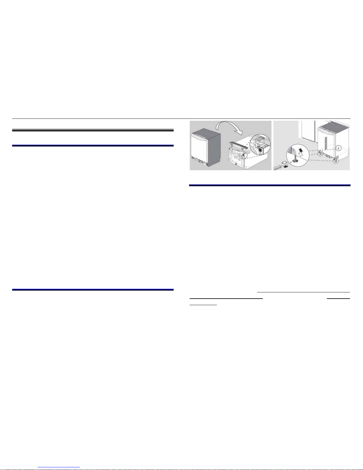
2.2 Alignment
Carefully place dishwasher on its back to pre-adjust all three feet
-- turn feet clockwise to raise or counter-clockwise to lower.
Maximum height with feet fully extended is 34.5”. Place
dishwasher upright, then level side to side and front to back.
When done, insert leg leveler locking screw in back foot.
Regardless of countertop surface, mounting brackets are
attached on the side of dishwashers. They are screwed into
screw bosses on the side dishwasher frame, then into the
cabinetry.
2.3 Electrical connection
Install according to national and local codes.
Carefully place dishwasher on its back to make electrical
connections to the terminal block. Turn power off at the fuse box.
Extend power cord approximately 21” from the left side of the
opening, and 30” from the back wall, making sure the cord
doesn’t contact any moving parts.
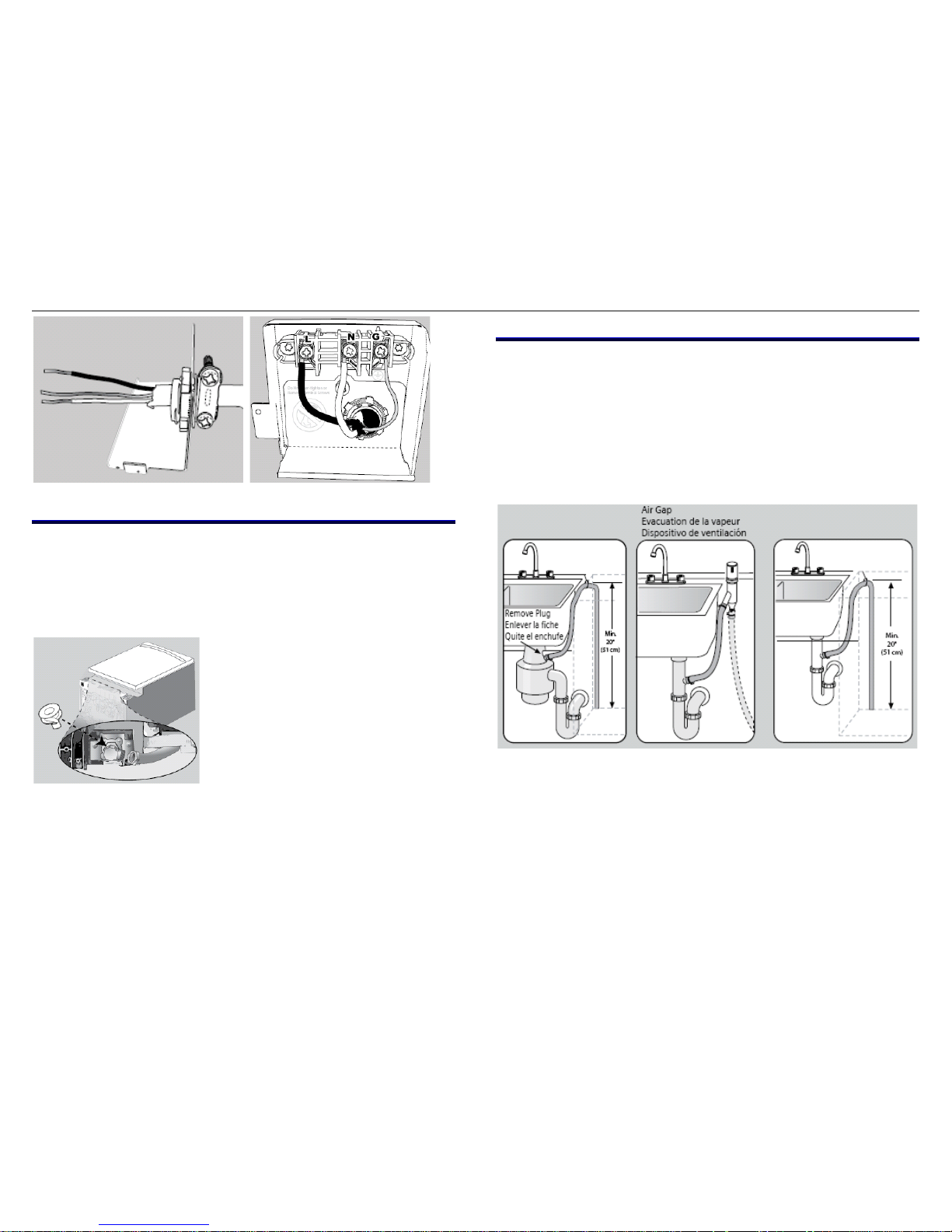
Strip outer casing of electrical wire to expose 2.5" - 3" (65 - 76
mm) of inner wires, then strip 1/2" (13 mm) casing from each
wire. If plugging the dishwasher into an outlet, contact customer
service to order approved power cord accessory kit
(SGZPC001UC). Insert cord through a strain relief (not included)
and install to strain relief plate. Attach wires to terminal block
(black – L (hot), white – N (neutral) & green – G (ground).
Unscrew terminal screws, but don’t loosen or remove them as
they may become damaged. Attach wires snugly, but don’t
overtighten.
702_58300000130262_ara_en_c Page 4 of 50
2.4 Water connection
Install according to national and local codes.
Carefully place dishwasher on its back to make water
connections to the water inlet valve. Use a 90º elbow fitting with
Teflon tape as needed. Don’t overtighten.
Attach the hot water line to the 90° elbow and route it underneath
the unit toward the hot water connection. Make sure the line
doesn’t contact any moving parts.
2.5 Drain and condensation hose connections
Plumbing installations will vary - refer to local codes. The
maximum length of the drain hose, including leading to an air gap
(if any) is 150" (381 cm). Make sure a high loop is raised at least
20" (51 cm) above the floor.
Drain hose has its own adapter – connect directly to plumbing
connection and secure with supplied hose clamp. Don’t connect
to condensation hose.
702_58300000130262_ara_en_c Page 5 of 50
3 OPERATION
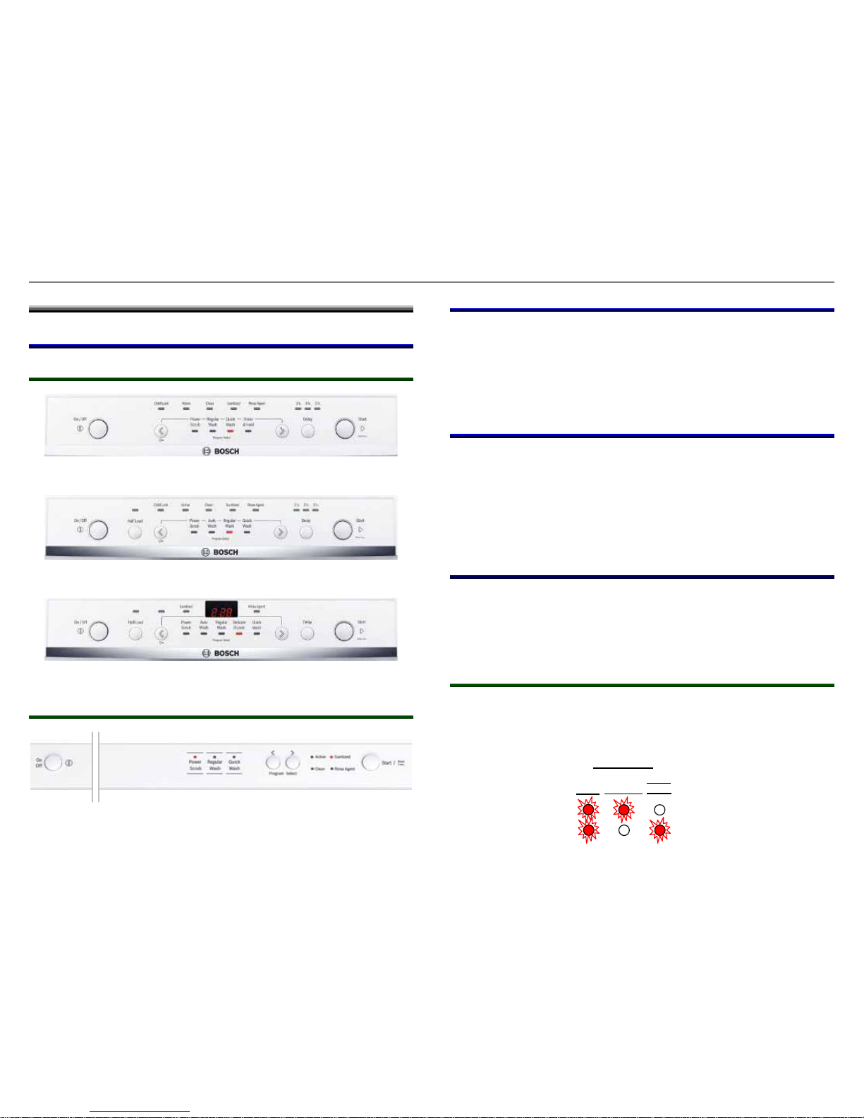
3.1 Control layout
3.1.1 SHE models
3.1.2 SHX models
3.2 Using controls
Wash programs don’t have dedicated buttons, but are selected
by scrolling with left (“<”) and right (“>”) scroll buttons. After
turning on dishwashers, scroll left or right to the desired wash
program (shown by lit LED displays between scroll buttons). To
start the desired program, press the Start button.
3.3 Reset (“Cancel – drain”)
To reset, press and hold Start button until Active light goes out
or when display shows “0.01” -- for integrated models (with
buttons on top of the door), open door just enough to expose
buttons. Wait about one minute for dishwasher to stop draining -with integrated models, door must be closed for dishwasher to
drain. To reset dishwasher, turn it off after it stops.
SHE4AM02UC
3.4 Changing basic settings
SHE4AM12U
Extra Dry feature can be turned on or off and rinse-aid dosage
can be changed using dishwasher controls. For many integrated
models, End of Cycle tone volume can also be changed.
SHE5AM02UC
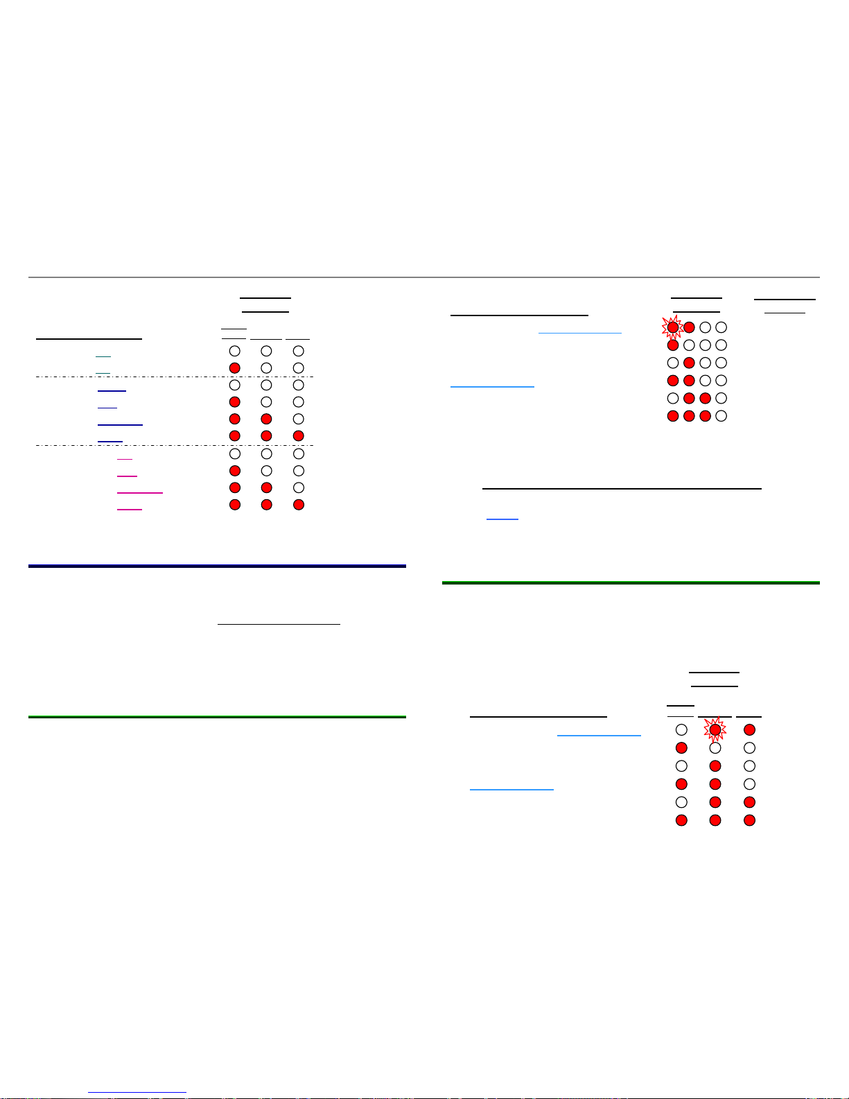
3.4.1 SHE “Evolution” models
Turn dishwasher on, press and hold “>” button, then press and
hold Start button. Clean and Sanitized lights will be flashing
(Extra Dry mode). When lights are flashing, release buttons.
SHE Extra Dry
SHE Rinse Aid
SHE lights
Clean
Sanitized
Rinse
Agent
SHX3AM02UC
702_58300000130262_ara_en_c Page 6 of 50
Press “>” button to scroll between Extra Dry and Rinse Aid
modes. Press “<” button to scroll to desired setting. Press Start
button to save settings and exit basic settings.
3.4.2 SHE “Evolution” models
Turn dishwasher on, press and hold “>” button, then press and
hold Start button. Sanitized light will be flashing (Extra Dry
mode). When light is flashing, release button.
Press “>” button to scroll between Extra Dry and Rinse Aid
modes. Press “<” button to scroll to desired setting. Press Start
button to save settings and exit basic settings.
3.4.3 SHX “Integra” models
Turn dishwasher on, press and hold “>” button, then press and
hold Start button. Clean and Sanitized lights will be flashing
(Extra Dry mode). When lights are flashing, release buttons.
Press “>” button to scroll between Extra Dry, Rinse Aid and
Cycle Tone Volume modes. Press “<” button to scroll to desired
setting. Press Start button to save settings and exit basic
settings.
SHE LED
displays
SHE basic settings
Extra Dry (off
)
Extra Dry (on
)
Rinse Aid (none
)
Rinse Aid (low
)
Rinse Aid (medium
)
Rinse Aid (high
)
SHE Extra Dry
SHE lights
Clean
Sanitized
Rinse
Agent
SHE basic settings
Extra Dry (off
)
Extra Dry (on
)
Rinse Aid (none
)
Rinse Aid (2 seconds
)
Rinse Aid (3 seconds
)
Rinse Aid (4 seconds
)
Rinse Aid (5 seconds
)
Rinse Aid (6 seconds
)
Rinse Aid (7 seconds
)
SHE digital
display
d:00
d:01
r:00
r:01
r:02
r:03
r:04
r:05
r:06
SHX Extra Dry
SHX Rinse Aid
SHX Cycle Tone
SHX lights
Clean
Sanitized
Rinse Aid
Active
Clean
Sanitized
Rinse Aid
Active
Clean
Sanitized
Rinse Aid
Active
702_58300000130262_ara_en_c Page 7 of 50
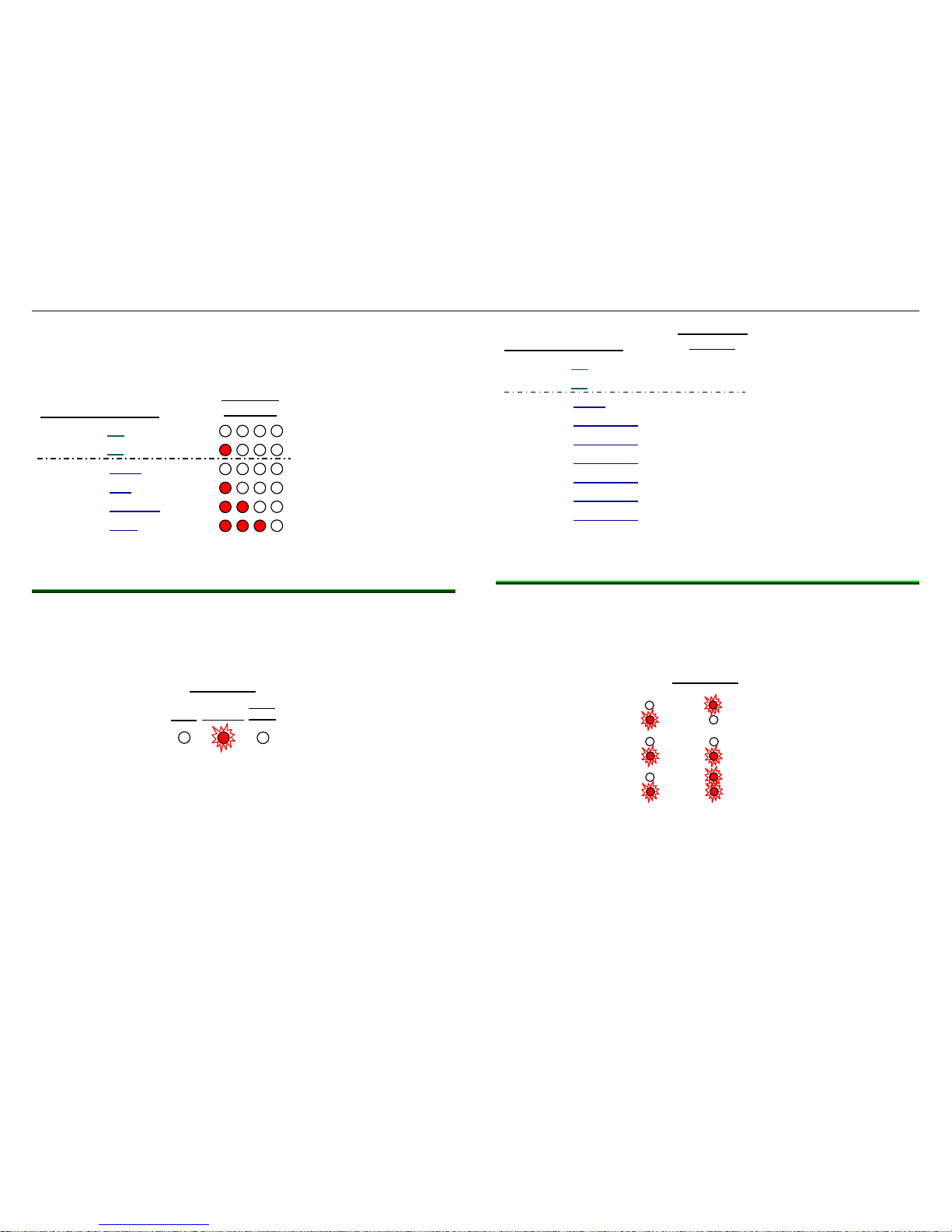
3.5 Special programs (codings)
Controls can run customer service tests, show error codes, run
sales demo programs and run factory tests. The same procedure
is used to access all programs – don’t run factory tests.
All programs are listed for questions about unknown codes or
displays occasionally encountered on dishwashers.
3.5.1 SHE “Evolution” models
To enter Special programs, press and hold “>” and Delay
buttons, then turn dishwasher on. When Special programs are
accessed, left program light will flash and 2
nd
program light from
left will be lit (see below). For models with digital displays, the
display will show “P0”.
To scroll through programs, press “<” button.
To start programs shown with “*”, press “>” button.
To exit Special programs, turn dishwasher off
Programs shown with “+” are started with the Start button
(don’t run these programs).
Run only programs shown in bold type (error codes,
customer service & sales demo).
3.5.2 SHX “Integra” models
To enter Special programs, press and hold “<” and “>”buttons,
then turn dishwasher on. When Special programs are accessed,
Regular Wash light will flash and Quick Wash light will be lit
(see below).
SHE LED
displays
SHE Special programs
Error codes* / Functional test+
Customer service test*
High voltage test*
Endurance run+
UL program*
Showroom (sales demo)*
SHE digital
display
P0
P1
SHX basic settings
Extra Dry (off
)
P2
P3
P6
SHX Special programs
Error codes* / Functional test+
Customer service test*
High voltage test*
Endurance run+
UL program*
Showroom (sales demo)*
SHX LED
displays
Power
Scrub
Regula
r
Quick
Extra Dry (
on
)
Rinse Aid (none
)
Rinse Aid (low
)
Rinse Aid (medium
)
Rinse Aid (high
)
Tone Volume (off
)
Tone Volume (low
)
Tone Volume (medium
)
Tone Volume (high
)
SHX LED
displays
Power
Scrub
Regular Quick
702_58300000130262_ara_en_c Page 8 of 50
To scroll through programs, press “<” button.
To start programs shown with “*”, press “>” button.
To exit Special programs, turn dishwasher off.
Programs shown with “+” are started with the Start button
(don’t run these programs).
Run only programs shown in bold type (error codes,
customer service & sales demo).
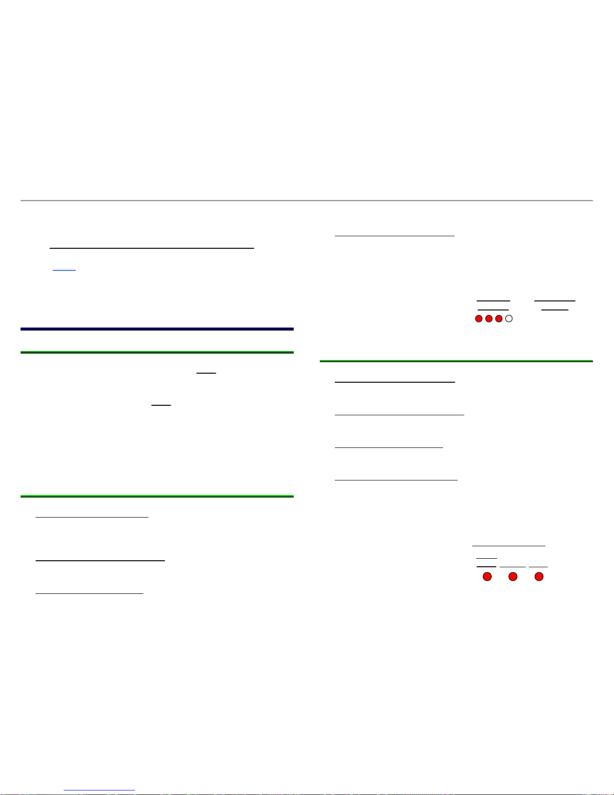
3.6 Sales demo (showroom) program
3.6.1 General instructions
Unlike with traditional dishwashers, do NOT disconnect drain
pumps when using sales demo programs. Dishwasher controls
run safety checks – if drain pumps or heat pumps are
disconnected, dishwashers will NOT run.
No disconnections are needed – just add one (1) gallon of water
(with bacteria stat) to dishwasher tanks. Heat pumps will run and
lights will light when program buttons are pushed. Drain pumps
do not run. It’s not necessary to plug drain hoses, but it’s a good
practice to prevent any possible water leakage.
3.6.2 SHE “Evolution” models
Entering Special programs – Press and hold “>” and Delay
buttons, then turn dishwasher on. Left program light will flash
and 2nd program light from left will be lit. (on SHE5AM models,
digital display will show “P0”).
Selecting sales demo program - Press “<” button to scroll to
customer service test program. Left three LED displays will
be lit (on SHE5AM models, digital display will show “P7”).
Using sale demo program - Press “>” button to start program.
Active and Regular Wash lights will always be lit (on
SHE5AM models, digital display will always show “1:23”).
Pressing buttons will light corresponding light.
Exiting sales demo program - Press and hold “>”and Delay
buttons, then turn dishwasher off to exit program. Pressing
on/off button during sales demo program shows how
dishwasher resets, but does not reset dishwasher, turn
dishwasher off or exit sales demo program.
SHE LED
displays
SHE Sales demo pgm*
SHE digital
display
P7
3.6.3 SHX “Integra“ models
Entering Special programs – Press and hold “<” and
“>”buttons, then turn dishwasher on. Regular Wash light will
flash and Quick Wash light will be lit.
Selecting sales demo program - Press “<” button to scroll to
customer service test program. All three LED displays will be
lit.
Using sale demo program - Press “>” button to start program.
Active and Regular Wash lights will always be lit. Pressing
buttons will light corresponding light.
Exiting sales demo program - Press and hold “<” and “>”
buttons, then turn dishwasher off to exit program. Pressing
on/off button during sales demo program shows how
dishwasher resets, but does not reset dishwasher, turn
dishwasher off or exit sales demo program.
SHX
LED dis
play
s
Power
Scrub
Regular
Quick
SHX Sales demo program *
702_58300000130262_ara_en_c Page 9 of 50
4 COMPONENTS
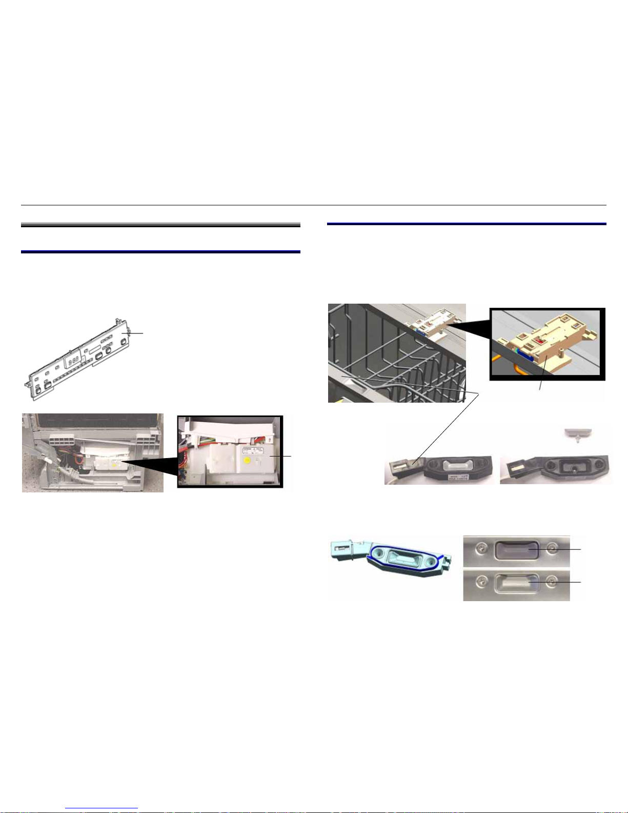
4.1 Control and power modules
Ascenta dishwashers have two control modules, a control module
(with display, lights & buttons) in the fascia (control) panel and a
power module in the base on the right side. The power module
controls the BLDC drain pump and heat pump.
The wire harness connected to the control module can either be a
separate harness or the 1-piece dishwasher harness, depending
on when the dishwasher was built. The wiring is the same, with
the only difference being whether the dishwasher has three
harnesses or one harness.
4.2 Door latch
The door latch is mounted on top of the tank and doesn’t contain
a microswitch. It uses a Hall-effect sensor in the door to sense
the door latch magnet to determine if the door is open or closed.
The Hall-effect sensor is held by two T-10 Torx screws. The door
latch is held by one T-20 Torx screw and two tank tabs.
1
1. Control module (in fascia panel)
2. Power module (in base)
Starting FD8907, the small door latch face plate has been
integrated into the tray insert (and can’t be obtained separately).
1
2
1. Door latch
2. Hall effect sensor
1. Newer integrated face plate
2. Older separate face plate
1
2
2
702_58300000130262_ara_en_c Page 10 of 50
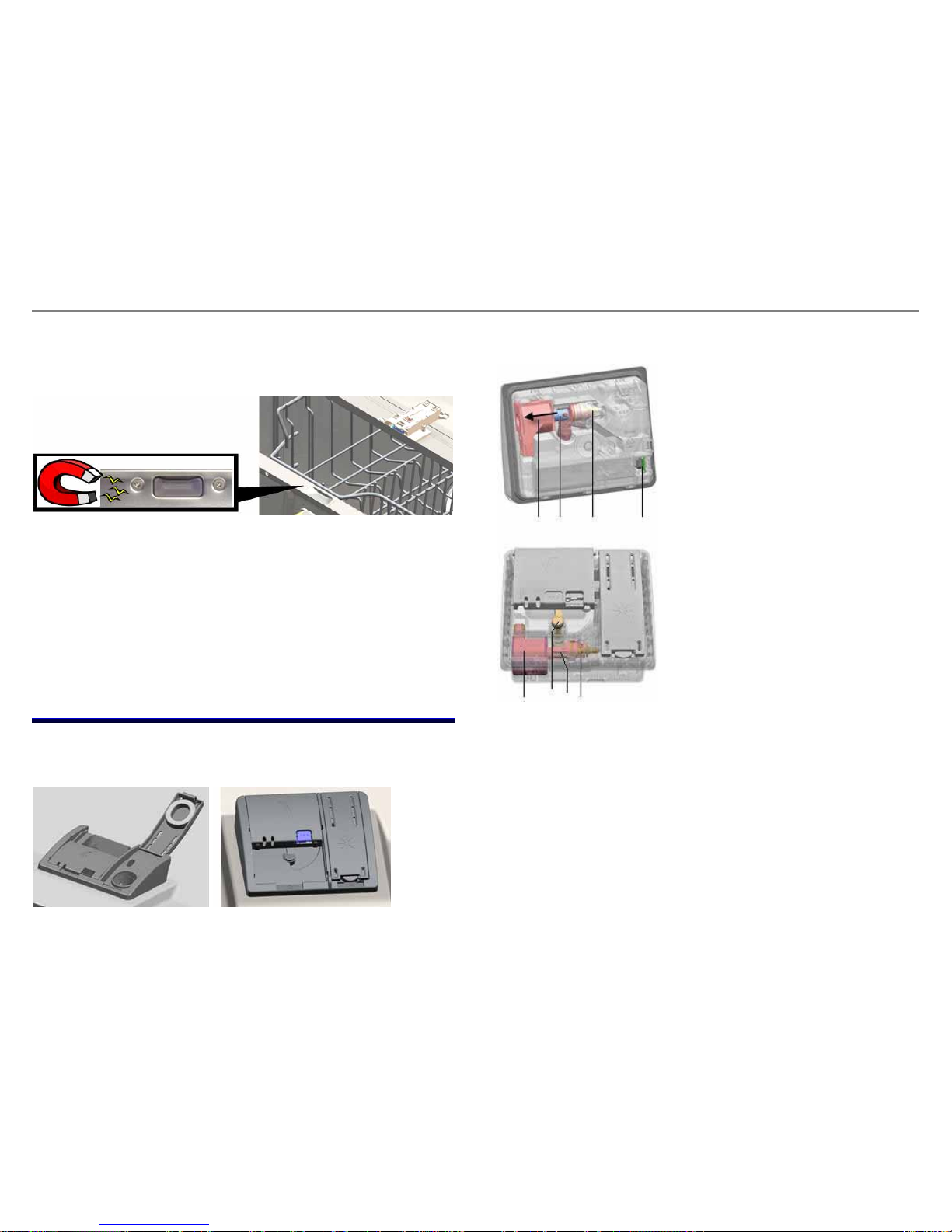
The dishwasher won’t start if the door isn’t closed securely. Push
the door closed until the door latch closes (i.e. until the latch
clicks). If the dishwasher starts, educate the customer on closing
the door securely.
If the dishwasher won’t start when the door has been securely
closed, check the door latch with a magnet. Hold the magnet
over the Hall Effect sensor (located just left of the left screw) – if
the dishwasher starts, the sensor didn’t sense the door latch
magnet.
Occasionally a door can catch on the door seal and not close
securely. If the door or door seal is misaligned, realign it. If the
door latch is broken, replace it.
4.3 Dispenser
The dispenser, located in the middle of the inner door, reliably
dispenses detergent and rinse-aid.
During each wash program, the dispenser operates twice, once
to dispense detergent and again to dispense rinse-aid.
1. Coil
2. Actuator
3. Rinse-aid pump
4. Optical rinse-aid sensor
5. Cover release lever
The coil (1) moves the detergent
cover actuator (2) and is powered
by 160 VDC pulses from the
control. When the coil is
switched on, the actuator moves
to the left. The actuator is
connected by a plastic link to the
detergent cover release lever (5).
When the actuator turns the
lever, the detergent cover opens.
1
34
2
1
2
5
3
A “latching mechanism” between the coil actuator and rinse-aid
valve prevents rinse aid from being dispensed when the coil is
initially actuated. After the detergent cover has opened, the
mechanism changes position like a ballpoint pen (when it’s
clicked), preventing the detergent cover from moving and
allowing the rinse-aid pump to dispense rinse aid.
Each 160 VDC control pulse dispenses 1 ml of rinse aid. The
total amount of rinse-aid depends on the dispenser setting. A
vent equalizes the pressure in the dispenser so rinse-aid is
dispensed accurately.
702_58300000130262_ara_en_c Page 11 of 50
The actuator is “reset” when the detergent door is opened so the
detergent cover opens first the next time the coil is activated.
Detergent tablets dissolve more slowly if there’s moisture left in
the detergent dispenser. Two plastic ribs in the detergent cup
prevent detergent tablets from “sticking” to the cup.
CAUTION: Inner door edges are sharp! Cover door
edges and remove dispenser carefully.
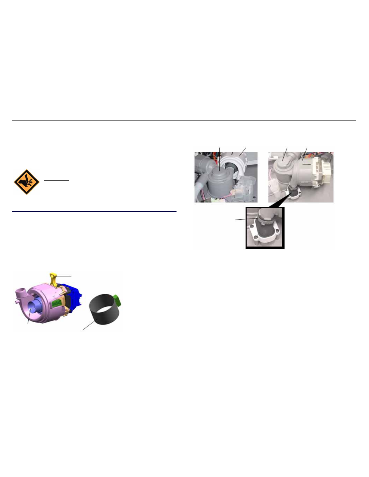
4.4 Heat pump
There’s no flow-through heater, flow switch or Hi-Limit cutout –
the circulation pump has a flow-through heated cylinder. The 120
VAC, 1200W heater cylinder provides more heating surface area
and heats water a bit faster than traditional flow-through heating
elements (~ 2ºF / minute). The circulation pump (portion) has a
3-pole BLDC motor controlled by the power module.
The dishwasher won’t run if the heat pump is disconnected or
disabled.
The heat pump is best accessed from the bottom even though it’s
accessible from the back as well.
2
2
1
1
3
1. Heat pump
2. Sump
3. Clamp
1. Pump suspension strap
2. Heating element
1
3. Seal ring
2
3
702_58300000130262_ara_en_c Page 12 of 50
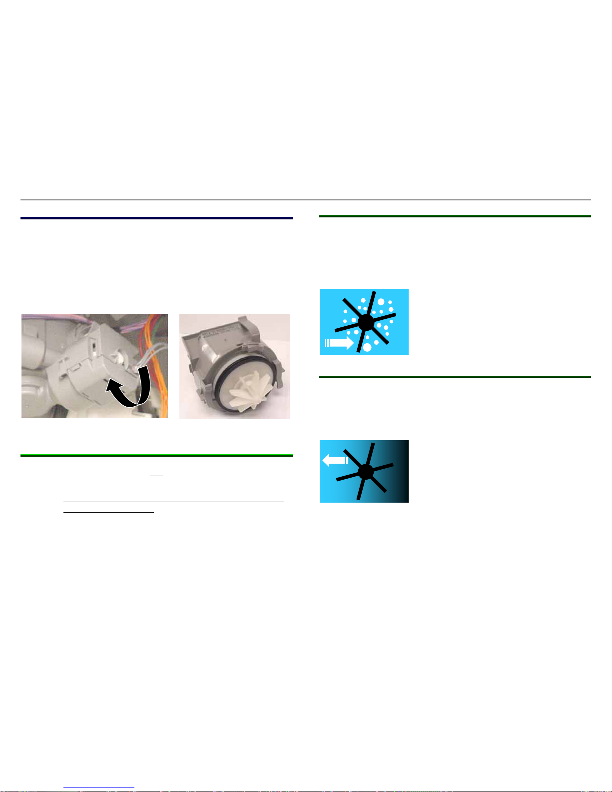
4.5 Drain pump
The BLDC 9-vane drain pump has variable speed and direction.
The power control module controls speed and direction, detects
end of draining and blocked rotor and corrects locked rotor
conditions. The dishwasher won’t run if the drain pump is
disconnected or disabled.
To remove the drain pump, rotate it clockwise and pull it out.
4.5.1 Solving installation issues
Often improper installations, not drain pump issues, cause
dishwashers to not drain properly.
Must have drain hoses with high loops (min. 20” high)
or drains with air gaps.
Drain hoses are 6’ long and can be up to 10’ long.
Secure drain hoses to rear of dishwashers with non-
metal bands.
Make sure drain hoses aren’t kinked.
4.5.2 Cavitating
Cavitating may occur in any type of pump when impellers spin
faster (from low inlet or outlet pressure), creating air pockets
around impellers. Cavitating pumps can be noisy. Air
gaps/high loops keep water contacting pump outlets, preventing
air pockets from forming.
4.5.3 Siphoning
Siphoning may occur in any type of drain pump when low water
flow allows a siphon (suction) to develop, pulling waste water
back into the pump. Sump check valves along with air
gaps/high loops prevent siphons from being created.
702_58300000130262_ara_en_c Page 13 of 50
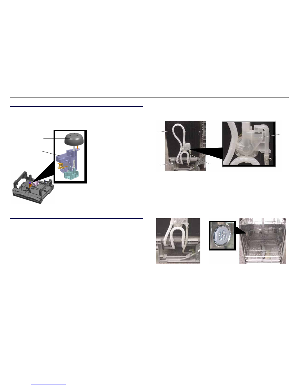
4.6 Float
The float is a safety device which starts the drain pump if there’s
too much water in the tank.
4.7 Water inlet / condensation system
Unlike prior dishwashers, Ascenta dishwashers use a common
water inlet and condensation system. Instead of feeding water
into the bottom of the tank, dishwashers fill into the left side of the
tank. Instead of condensation exiting from the right side of the
tank, it exits the left side of the tank through the water inlet.
There are three hoses connected to the water inlet system, the
water inlet hose (from the water inlet valve), condensation
(breather) hose and internal drain hose. The internal drain hose
has a factory made high loop (~ 15” above the floor) and
connects to the external customer drain hose.
Ascenta dishwashers use a time-fill.
Maximum customer (external) drain hose length is 92”.
Water inlet system and hoses are shown below.
1
2
3
4
2
1
1. Condensation tube
2. Drain hose (with high loop)
3. Water inlet hose
1. Float assy.
4. Water inlet
2. Float (located inside
of tank)
Drain hose high loop and left side condensation exit are shown
below.
702_58300000130262_ara_en_c Page 14 of 50
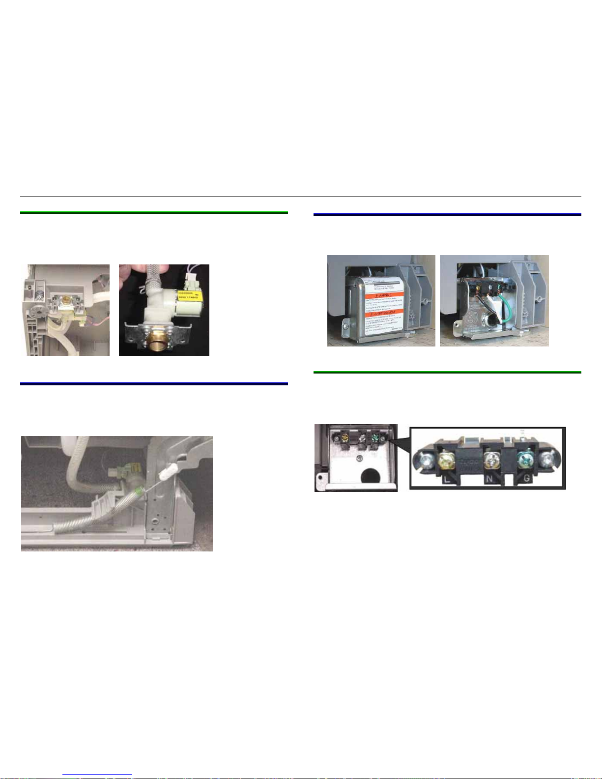
4.7.1 Water inlet valve
Ascenta dishwashers use standard horizontal coil water inlet
valve with (Rast 5) connector. The valve nestles in the left side of
the base on base tabs and is held into place with two screws.
4.8 Door spring
The door spring mechanism is simple, requiring no pulleys or
cords. A long narrow spring connects between the base and
hinge lever (using a plastic connector) to provide proper tension.
The spring has loops at both ends and connects to a long slot in
the base. Springs are color coded for specific tensions.
4.9 Terminal box
All dishwashers have terminal boxes with covers and conduit
exits.
4.9.1 Terminal block
Terminal blocks clearly show line (L), neutral (N) & ground (G)
connections. Dishwasher wire harnesses have spade terminals
which connect to terminals on the rear of the terminal block.
Terminal blocks can’t be installed in the field – the terminal box
assy with terminal block must be ordered. The terminal box assy
assures the terminal block is properly grounded to the terminal
box.
702_58300000130262_ara_en_c Page 15 of 50
 Loading...