

Bosch SGH182, SGH182AF Operating/safety Instructions Manual
IMPORTANT: IMPORTANT : IMPORTANTE:
Read Before Using Lire avant usage Leer antes de usar
For English Version Version française Versión en español
See page 2 Voir page 12 Ver la página 22
1-877-BOSCH99 (1-877-267-2499) www.boschtools.com
Call Toll Free for
Consumer Information
& Service Locations
Pour obtenir des informations
et les adresses de nos centres
de service après-vente,
appelez ce numéro gratuit
Llame gratis para
obtener información
para el consumidor y
ubicaciones de servicio
SGH182
SGH182AF (SGH182+MA55)
Operating/Safety Instructions
Consignes de sécurité/d’utilisation
Instrucciones de funcionamiento y seguridad

Work area safety
Keep work area clean and well lit. Cluttered
or dark areas invite accidents.
Do not operate power tools in explosive
atmospheres, such as in the presence of
flammable liquids, gases or dust. Power
tools create sparks which may ignite the dust
or fumes.
Keep children and bystanders away while
operating a power tool. Distractions can
cause you to lose control.
Electrical safety
Power tool plugs must match the outlet.
Never modify the plug in any way. Do not
use any adapt e r plugs wi th earthe d
(grounded) power tools. Unmodified plugs
and matching outlets will reduce ris k of
electric shock.
Avoid body contact with earthed or grounded
surfaces such as pipes, radiators, ranges
and refrigerators. There is an increased risk
of electric shock if your body is earthed or
grounded.
Do not expose power tools to rain or wet
conditions. Water entering a power tool will
increase the risk of electric shock.
Do not abuse the cord. Never use the cord
for carrying, pulling or unplugging the power
tool. Keep cord away from heat, oil, sharp
edges or moving parts. Damaged or entangled
cords increase the risk of electric shock.
When operating a power tool outdoors,
use an extension cord suitable for outdoor
use. Use of a cord suitable for outdoor use
reduces the risk of electric shock.
If operating a power tool in a damp location
is unavoidable, use a Ground Fault Circuit
Interrupter (GFCI) protected supply. Use of
an GFCI reduces the risk of electric shock.
Personal safety
Stay alert, watch what you are doing and
us e common sense when operating a
power tool. Do not use a power tool while
you are tired or under the influence of drugs,
alcohol or medication. A moment of inattention
while operating power tools may result in
serious personal injury.
Use personal protective equipment. Always
wear eye protection. Protective equipment
such as dust mask, non-skid safety shoes, hard
hat, or hearing protection used for appropriate
conditions will reduce personal injuries.
Prevent unintentional starting. Ensure the
sw itch is in the off-position before
connecting to power source and / or battery
pa ck, pic king up or carrying the tool.
Carrying power tools with your finger on the
switch or energizing power tools that have the
switch on invites accidents.
Remove any adjusting key or wrench before
turning the power tool on. A wrench or a
key left attached to a rotating part of the
power tool may result in personal injury.
Do not overreach. Keep proper footing and
balance at all times. This enables better
con trol of t he power t ool i n une xpected
situations.
Dress properly. Do not wear loose clothing
or jewelry. Keep your hair, clothing and
gloves away from moving parts. Loose
clothes, jewelry or long hair can be caught in
moving parts.
If devices are provided for the connection
of dust extraction and collection facilities,
ensure these are connected and properly
used. Use of dust collection can reduce dust-
related hazards.
Power tool use and care
Do not force the p ower t ool. Us e the
correct power tool for your application. The
correct power tool will do the job better and
safer at the rate for which it was designed.
Do not use the power tool if the switch does
not turn it on and off. Any power tool that
cann o t b e controlled with the switch is
dangerous and must be repaired.
Read all safety warnings and all instructions. Failure to follow the warnings
and instructions may result in electric shock, fire and/or serious injury.
SAVE ALL WARNINGS AND INSTRUCTIONS FOR FUTURE REFERENCE
The term “power tool” in the warnings refers to your mains-operated (corded) power tool or
battery-operated (cordless) power tool.
!
WARNING
General Power Tool Safety Warnings
-2-

-3-
Safety Rules for Cordless Screwguns
Hold power tool by insulated gripping
surfaces, when performing an operation
where the fastener may contact hidden
wiring or its own cord. Fasteners contacting
a "live" wire may make exposed metal parts of
the power to ol " live" and could give the
operator an electric shock.
Do not drill, fasten or break into existing
walls or other blind areas where electrical
wiring ma y exist. If this situation is
unavoidable, disconnect all fuses or circuit
breakers feeding this worksite.
Always wear saf e t y g o g g les or eye
protection when using this tool. Dust and
debris may be expelled from the work piece
during normal operation.
Secure the material being fastened. Never
hold it i n your h a n d or a c ross legs.
Unstable support can cause the drill bit to
bind causing loss of control and injury.
Neve r leave the trigger l o cked "ON".
Before plugging the tool in, check that the
trigger lock is "OFF". Accidental start-ups
could cause injury.
Position the cord clear of rotating driver.
Do not wrap the cord around your arm or
wrist. If you lose control and have the cord
wrapped around your arm or wrist it may
entrap you and cause injury.
Be aware of the location and setting of the
switch "Lock-ON" button. If the switch is
locked "ON" during the use, be ready for
emergency situations to switch it "OFF", by
first pulling the trigger then immediately
releasing it without pressing the "Lock-ON"
button.
Be prepared for a strong reaction torque
when "seating" or removing a screw. The
driver motor housing will tend to twist in the
opposite direction when "seating" or
removing a screw.
Disconnect the plug from the power source
a
nd/or the battery pack from the power tool
before making any adjustments, changing
accessories, or storing power tools. Such
preventive safety measures reduce the risk of
starting the power tool accidentally.
Store idle power tools out of the reach of
children and do not allow persons unfamiliar
with the power tool or these instructions to
operate the power tool. Power tools are
dangerous in the hands of untrained users.
Maintain power tools. Check for misalignment
or binding of moving parts, breakage of
parts and any other condition that may
affect the power tool’s operation. If damaged,
have the power tool repaired before use.
Many acci d ents are caused by poorly
maintained power tools.
Keep cutting tools sharp and clean. Properly
maintained cutting tools with sharp cutting
edges are less likely to bind and are easier to
control.
Use the power tool, accessories and tool
bits etc. in accordance with these instructions,
taking into account the working conditions
and the work to be performed. Use of the
power tool for operations different from those
intended could result in a hazardous situation.
Battery tool use and care
Recharge only with the charger specified
by the manufacturer. A charger that is
suitable for one type of battery pack may
create a risk of fire when used with another
battery pack.
Use power tools only with specifically
designated battery packs. Use of any other
battery packs may create a risk of injury and
fire.
When battery pack is not in use, keep it
away from other metal objects like paper
clips, coins, keys, nails, screws, or other
sma ll metal object s, that can ma ke a
connection from one terminal to another.
Shorting the battery terminals together may
cause burns or a fire.
Under abusive conditions, liquid may be
ejected from the battery; avoid contact. If
contact accidentally occurs, flush with
water. If liquid contacts eyes, additionally
seek medical help. Liquid ejected from the
battery may cause irritation or burns.
Service
Have your power tool serviced by a qualified
repa i r pers o n usin g only identic a l
replacement parts. This will ensure that the
safety of the power tool is maintained.

-4-
Additional Safety Warnings
GFCI and personal protection devices like
electrician’s rubber gloves and footwear will
further enhance your personal safety.
Do not use AC only rated tools with a DC
power supply. While the tool may appear to
work, the electrical components of the AC
rated tool are likely to fail and create a hazard
to the operator.
Keep handles dry, clean and free from oil
and grease. Slippery hands cannot safely
control the power tool.
Develop a periodic maintenance schedule
for your tool. When cleaning a tool be
careful not to disassemble any portion of
th e tool since internal wires may be
misplaced or pinched or safety guard return
sp rings ma y b e improperly mou nted.
Certain cleaning agents such as gasoline,
carbon tetrachloride, ammonia, etc. may
damage plastic parts.
Risk of injury to user. The power cord must only
be serviced by a Bosch Factory Service Center
or Autho rized Bosch Service Station.
Some dust created by power
sanding, sawing, grinding,
drilling, and other construction activities
contains chemicals known to cause cancer,
birth defects or other reproductive harm.
Some examples of these chemicals are:
• Lead from lead-based paints,
• Crystalline silica from bricks and cement and
other masonry products, and
• Arsenic and chromium from chemically-
treated lumber.
Your risk from these e x p osures v a ries,
depending on how often you do this type of
work. To reduce your exposure to these
chemicals: work in a well ventilated area, and
work with approved safety equipment, such as
those dust masks that are specially designed
to filter out microscopic particles.
!
WARNING
D
o not use dull o r damag ed bits and
accessories. Bits and accessories in these
conditions may cause the tool to react in an
unpredictable manner.
Check to see that keys and adjusting
wrenches are removed from the driver
before switching the tool "ON". Keys or
wrenc h e s can fly a w ay at high v e locity
striking you or a bystander.
Do not run the tool while carrying it at
your side. A spinning drill bit could become
entangled with clothing and injury may result.
N
ever place any part of your body in a
pinch point area. When operating auto-feed
attachment consider where your hand is
located. If it is within a pinch point, strongly
consider an alternative position. Injuries
occur when hands or fingers are between
moving and stationary parts during t h e
pinching movement.
-5-
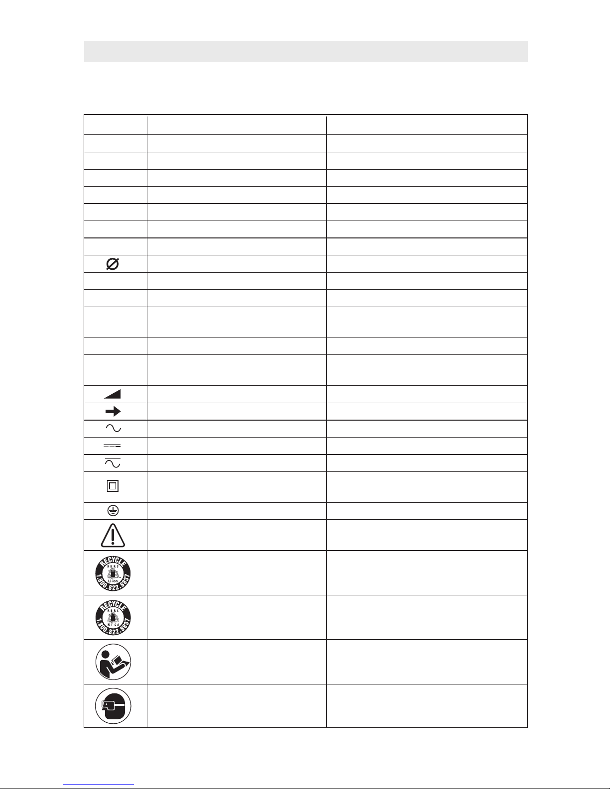
I
MPORTANT: Some of the following symbols may be used on your tool. Please study them
and learn their meaning. Proper interpretation of these symbols will allow you to operate the
tool better and safer.
Symbol Name Designation/Explanation
V Volts Voltage (potential)
A Amperes Current
Hz Hertz Frequency (cycles per second)
W Watt Power
kg Kilograms Weight
min Minutes Time
s Seconds Time
Diameter Size of drill bits, grinding wheels, etc.
n
0
No load speed Rotational speed, at no load
n Rated speed Maximum attainable speed
.../min Revolutions or reciprocation Revolutions, strokes, surface speed,
per minute orbits etc. per minute
0 Off position Zero speed, zero torque...
1, 2, 3, ... Selector settings Speed, torque or position settings.
I, II, III, Higher number means greater speed
Infinitely variable selector with off Speed is increasing from 0 setting
Arrow Action in the direction of arrow
Alternating current Type or a characteristic of current
Direct current Type or a characteristic of current
Alternating or direct current Type or a characteristic of current
Class II construction Designates Double Insulated
Construction tools.
Earthing terminal Grounding terminal
Warning symbol Alerts user to warning messages
Li-ion RBRC seal Designates Li-ion battery recycling
program
Ni-Cad RBRC seal Designates Ni-Cad battery recycling
program
Read manual symbol Alerts user to read manual
Wear eye protection symbol Alerts user to wear eye protection
Symbols
0

-6-
This symbol designates that this tool is listed by Underwriters Laboratories.
This symbol designates that this tool is listed by the Canadian Standards
Association.
This symbol designates that this tool is listed by the Canadian Standards
Association, to United States and Canadian Standards.
This symbol designates that this tool complies to NOM Mexican Standards.
This symbol designates that this tool is listed by the Intertek Testing
Services, to United States and Canadian Standards.
Symbols (continued)
IMPORTANT: Some of the following symbols may be used on your tool. Please study them
and learn their meaning. Proper interpretation of these symbols will allow you to operate the
tool better and safer.
This symbol designates that this component is recognized by Underwriters
Laboratories.
This symbol designates that this tool is listed by Underwriters Laboratories,
to United States and Canadian Standards.
Designated pinch point area - avoid placing hands or fingers in these
areas.
-7-
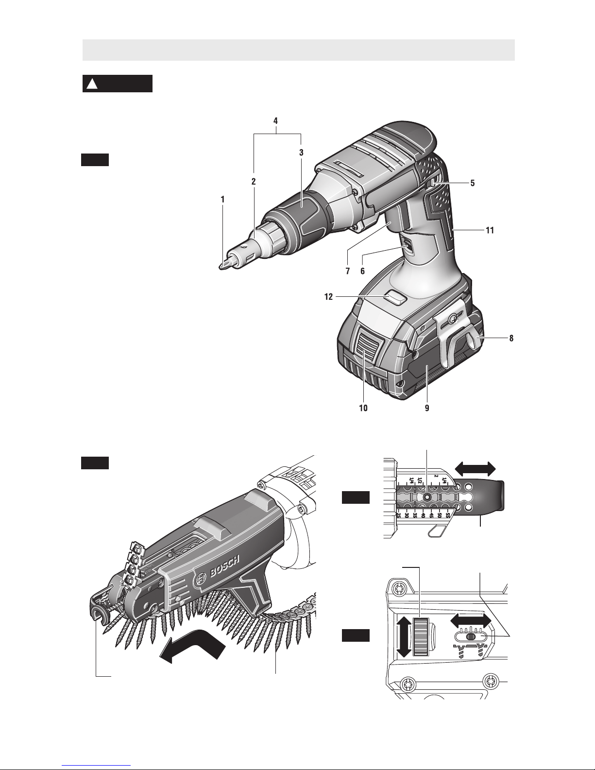
Functional Description and Specifications
Disconnect battery pack from tool before making any assembly,
adjustments or changing accessories. Such preventive safety measures
reduce the risk of starting the tool accidentally.
!
WARNING
NOTE: For tool specifications refer to the nameplate on your tool.
Collated Screw Strip
Work Contact
Element
Screw Length
Adjustment Button
Thumbwheel
Depth Scale
Work Contact
Element
MA55
Auto-feed
Attachment
1 Screwdriver bit
2 Stop bushing
3 Depth adjusting sleeve
4 Screwing depth control
5 Rotational direction switch
6 Lock-on button
7 Variable-speed control trigger switch
8 Belt clip
9 Battery pack
10 Battery unlocking button
11 Handle (insulated gripping surface)
12 LED to illuminate screwing location
SGH182 Screwgun
FIG. 3
FIG. 4
FIG. 2
FIG. 1

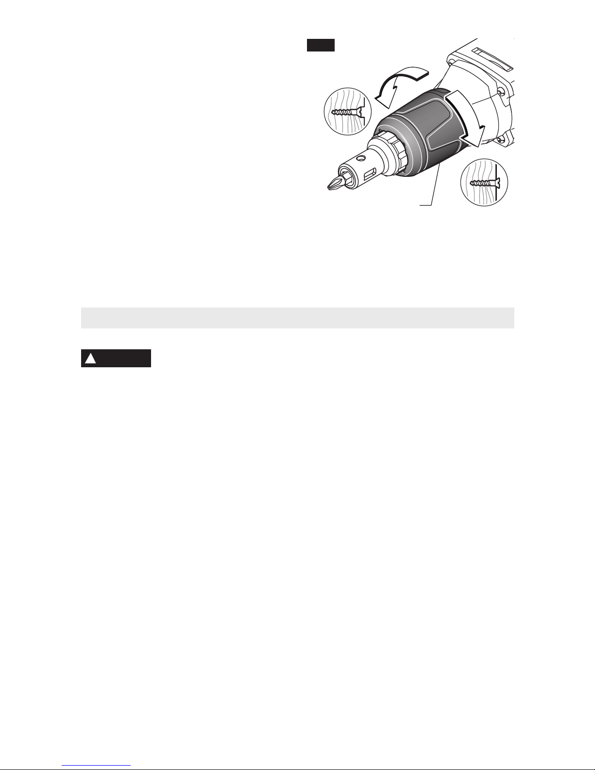
REPLACING SCREWDRIVER BIT
AND BIT HOLDER
1. Remove the depth control by grasping firmly
WITH YOUR HAND and pulling straight out.
DO NOT USE PLIERS (Fig. 5a).
2. Remove the screwdriver tip by leveraging the
hole on the side of the depth control against
the bit and pull the bit out (Fig. 5b). Similarly,
to remove the bit holder, leverage the hole
on the side of the depth gauge against the
screwdriver bit and also grasp the bit holder
with fingers from the same hand and pull
both the bit and bit holder out. If necessary,
pliers may be also used to remove either of
those items (Fig. 6).
3. Install bit holder (if removed) and new
screwdriver bit.
4. Then using your HAND ONLY, reinstall
depth control. Push depth control onto tool
until it snaps into place.
BELT CLIP
Your tool is equipped with a belt clip that allows
you to conveniently attach your driver to your
belt. This feature will allow you to have both
hands free when climbing a ladder or moving to
another work area (Fig. 1).
MULTI-BIT HOLDER
Your tool is also equipped with a multi-bit
holder (not shown) that can be mounted to the
side of the tool opposite the belt clip.
MOUNTING THE OPTIONAL AUTO-FEED
ATTACHMENT
1. Remove depth control and bit holder from the
tool.
2. Insert the special extended screwdriver bit into
the tool (Fig. 7).
3. Slide the auto-feed attachment MA55 over the
special extended screwdriver bit to the stop on
the motor housing (Fig. 7).
INSERTING A SCREW STRIP
Disconnect the plug from the
power source and/or battery
pack from power tool before making any
adjustments, changing accessories, or
storing power tools. Such preventative safety
measures reduce the risk of starting the power
tool accidentally.
1. After auto-feed attachment has been mounted
-8-
Assembly
Screwdriver
bit
Bit
Holder
!
WARNING
FIG. 6
Bit
Holder
FIG. 5b
Depth control
Screwdriver
bit
FIG. 5a
Depth control
Special Extended
Screwdriver Bit
Auto-feed
Attachment
(MA55)
FIG. 7
t
o tool, slide collated screw strip through the
strip guide on the auto-feed attachment (Fig. 2).
2. To avoid jamming screws into auto-feed
attachment, carefully slide collated screw strip
through the guide strip until first screw is
engaged in the self-feeding mechanism (Fig. 2).
3. An engaged screw strip must exit through the
top of the self-feeding mechanism.
A
fter screw strip is installed,
do not pull strip backwards.
Any attempt to pull screw strip through the
bottom of the self-feeding mechanism may
damage the auto-feed attachment. To remove
screw strip, pull strip from the top of the selffeeding mechanism.
!
CAUTION
Operating Instructions
This tool is intended for driving and removing
scr ews. I t is not suited for high-torque
applications such as driving TEK® screws.
VARIABLE SPEED CONTROLLED
TRIGGER SWITCH
Your tool is equipped with a variable speed
trigger switch. The tool can be turned "ON" or
"OFF" by squeezing or releasing the trigger.
The speed can be adjusted from the minimum
to maximum nameplate RPM by the pressure
you apply to the trigger. Apply more pressure
to increase the speed and release pressure to
decrease speed (Fig. 1).
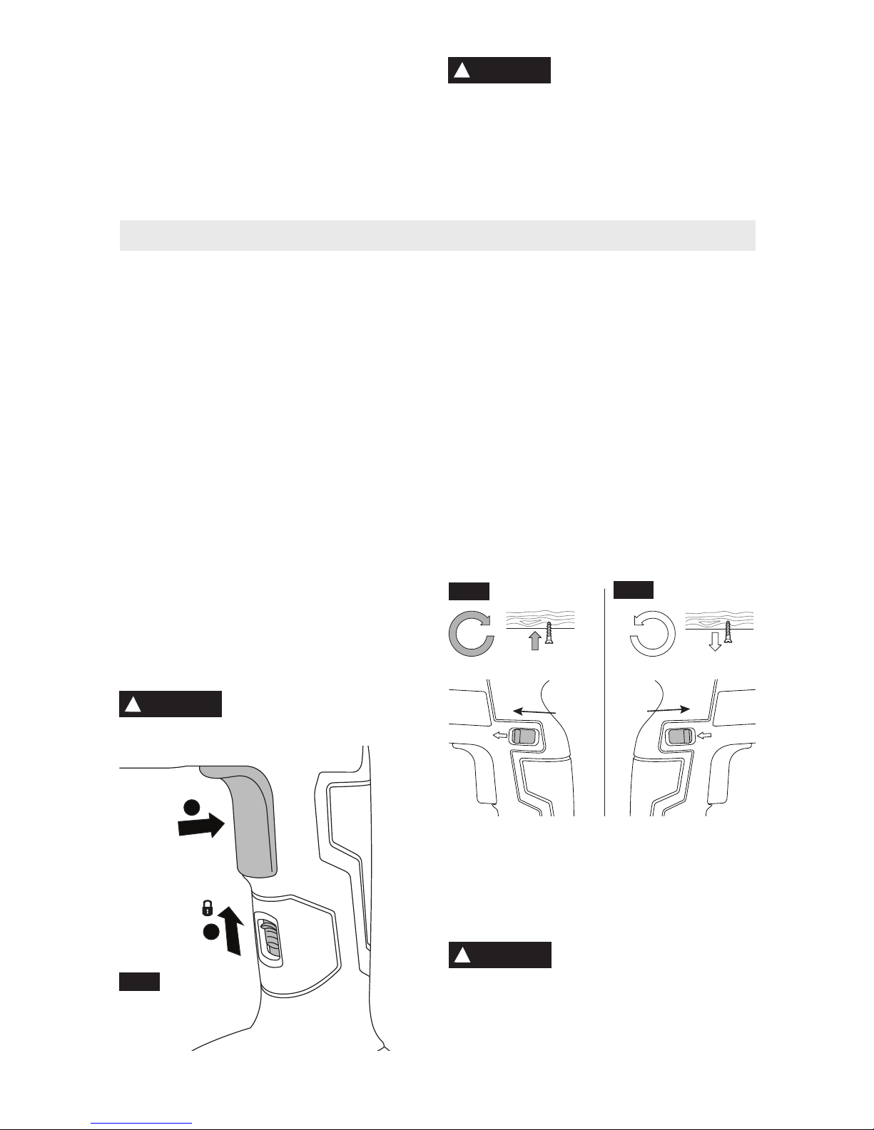
"LOCK-ON" BUTTON
The "Lock-ON" button, located below the
trigger allows for continuous operation at
maximum RPM without holding the trigger.
TO LOCK TRIGGER "ON": squeeze trigger,
push up on Lock-On button, and release
trigger (Fig. 8).
TO UNLOCK THE TRIGGER: squeeze trigger
and release it without depressing the "LockON" button.
If the “Lock-ON” button is
continuously be i n g d e -
pressed, the trigger can not be released.
PRESSURE CONTROLLED CLUTCH
This tool is equipped with a clutch that, when
combined with the Posi-Lok™ depth control,
stops the screw at the desired depth and
prevents the screw head from becoming
stripped or breaking the bit tip.
The clutch becomes engaged and begins
driving the screw into the work piece when
pressure is placed on the bit tip. The clutch
becomes disengaged and stops driving the
screw when the depth control contacts the
work piece and releases the pressure on the
bit tip.
ROTATION DIRECTION SWITCH
This control can be accessed on either side of
the tool to change the direction of rotation of the
bit.
Forward clockwise rotation:
Move the rotational direction switch to the
forward position (Fig 9a).
Reverse counterclockwise rotation:
Move the rotational direction switch to the
reverse position (Fig. 9b).
Do not change direction of
rotation until the tool comes
to a complete stop. Shifting during rotation of
the chuck can cause damage to the tool.
!
WARNING
!
CAUTION
2
1
FIG. 8
FIG. 9a
FIG. 9b
-9-
-10-
D
EPTH CONTROL
The depth control should be adjusted so that
the drywall screw is set slightly below the
drywall surface.
DEPTH ADJUSTMENT
Your driver will continue to drive as long as
enough pressure is applied to the bit to keep
the clutch engaged. The depth control, upon
contacting the w o r k, p r e v e n ts f u r t h e r
pressur e on the bit. D riving then s t o ps
regardless of pressure continued by the
operator.
1. Rotate the depth adjusting sleeve until the
depth stop reaches the desired position.
2. Each click of the depth adjusting sleeve
equals a 1/64 inch change in depth. One
full 360 degree turn equals 1/16 inch (Fig.
10).
3. Before beginning, alway s test-drive a
sample screw in t o a pi e ce of scrap
installation material to check desired depth
setting.
CAPACITIES
All available sharp-point screws in 14-25
gauge studs.
Depth Adjusting
Sleeve
FIG. 10
SGH182 with MA55 Operating Instructions
AUTO-FEED ATTACHMENT
Never place any part of your
body in a pinch point area.
When operating auto-feed attachment consider
where your hand is located. If it is within a pinch
point, strongly consider an alternative position.
Injuries occur when hands or fingers are
between moving and stationary parts during the
pinching movement.
ADJUSTING FOR SCREW LENGTH
1. The auto-feed attachment must be adjusted
to match length of screw being used.
2. Depress adjustment button on side of autofeed attachment (Fig. 3).
3. Slide self-feed mechanism for ward or
backwards to align arrow on the sliding
portion with the corresponding length printed
onto the auto-feed attachment (Fig. 3).
4. Allow depressed pin to snap back into place
by means of spring force.
DEPTH ADJUSTMENT
Your driver will continue to drive as long as
enough pressure is applied to the bit to keep
the clutch engaged. The auto-feed attachment
is capable of preventing further pressure on the
bi t. Driving then st ops regardless of the
pressure continued by the operator.
1. Turn the thumbwheel on the auto-feed
attachment downward to increase the depth
the screw will be driven (Fig. 4).
2. Turn the thumbwheel on the auto-feed
attachment upward to decrease the depth
the screw will be driven.
3. The selected depth is indicated symbolically
on the scale next to the thumbwheel (Fig. 4).
DRIVING SCREWS
Always work at a right angle to the work piece
to ensure the Auto-Feed mechanism is able to
operate properly. Failure to do so may cause
the Auto-Feed mechanism to jam or slip off the
screw head.
1. Depress trigger switch to engage the tool.
2. Set the work contact element on the autofeed attachment on the spot where the screw
is to be driven.
3. Apply uniform pressure to the tool in the
direction of the workpiece until the screw is
driven in.
4. By releasing pressure and disengaging tool
from driven screw, the next screw is loaded
Screws already driven cannot be removed or
retightened with the auto-feed attachment. To
remove or tighten screw, remove auto-feed
at tachment and use tool without the
attachment.
CAPACITIES
Collated screws 1” to 2-1/8” in length, 3/8” max
head diameter and 3/16” max shank diameter.
!
WARNING
 Loading...