

Bosch RF940U Installation Instructions Manual
RF940U
Wireless Passive Infrared Detector
With Pet Immunity
Installation Instructions
1.0 Description
The RF940U is a high performance Wireless Passive Infrared (PIR) Motion Sensor which uses advanced signal processing to provide outstanding catch
performance and unsurpassed false alarm immunity. It is designed to detect movement in the interior of a structure by sensing the Infrared energy emitted from
the human body as it moves across the sensor’s field of view. When motion is detected, the unit sends an alarm signal to the Control Panel. With Bosch Security
Systems’ Pet Friendly® pet immunity, the RF940U does not detect a dog up to 13.6 kg (30 lbs.), two cats, or numerous rodents.
2.0 Specifications
• Detection Range: 12.2 m x 12.2 m (40 ft. x 40 ft.) with look-down zone
• Mounting Height: 2.1 m to 2.7 m. (7 ft. to 9 ft.)
• Input Power: Provided by an internal 3 V battery. 3.3 VDC to
2.5 VDC operating voltage, <25μA nominal current
(PIR only). Battery types: DL123A, CR123
• Tamper: Wall and cover tampers
• Temperature: 0°C to +49°C (+32°F to +120°F) operating
temperature. Dynamic temperature compensation in
the operating range.
• Humidity: 0% to 85% non-condensing
• Dimensions: 11.4 cm x 6.4 cm x 4.1 cm (4.5 in. x 2.5 in. x 1.6 in.)
(HxWxD)
3.0 Installation
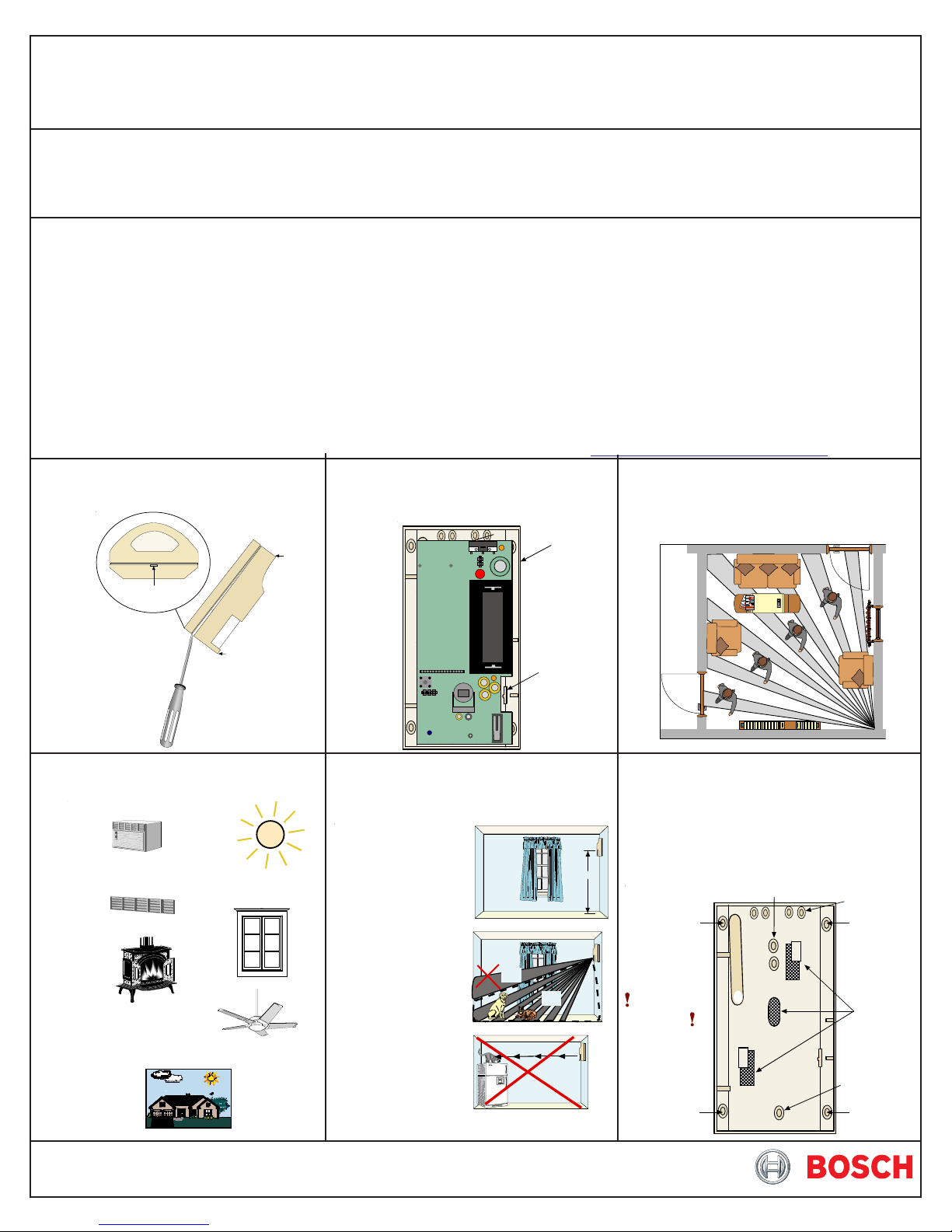
Step 1. Remove the cover using a small
flat-blade screwdriver.
Bottom of detector
Top
Step 2. Press the locking tab toward the
side of the baseplate and lift out the
board.
• RFI Immunity: Greater than 30 v/m 26 MHz to 1 GHz
• Options: B335 Swivel Mounting Bracket and B338 Ceiling Mount
Bracket. Using brackets may decrease the PIR range
and increase dead zones.
• Transmitter Interface:
- Recommended End of Battery Signaling: 2.5 VDC
- Alarm and Tamper Outputs: Active State, High Impedance Tri-State.
Inactive State, 1 mA Current Sink. V
- Minimum Alarm Output Time: 8 seconds (4 seconds Walk Test Mode)
Low = 0.25 VDC @ 1 mA
out
- Minimum Tamper Output Time: 4 seconds
- Alarm Lockout Time: 3 minutes
- Walk Test Mode: 90 seconds, retriggerable
• Reading Bosch Security Systems, Inc. Product Date Codes
For Product Date Code information, refer to the Bosch Security Systems,
Inc. Web site at: http://www.boschsecurity.com/datecodes/
Step 3. Select a mounting location. Mount
the sensor where an intruder will
most likely cross through the coverage
Baseplate
pattern.
Insert screwdriver here.
Avoid pointing the detector at:
Direct Hot or
Cold
Drafts
Air Conditioning
Outlets
Heat
Sources
Direct
Sunlight
Windows and
Uninsulated
Walls
Moving
Objects
Do not use outdoors.
Bottom
Locking
Ta b
Observe mounting recommendations.
Mount the detector
2.1m to 2.7 m (7 ft. to 9 ft.)
above the floor.
Upper areas are not
pet immune.
NO
OK
Don't point where pets
can climb.
NO
2.1 m to 2 .7 m
(7 ft. to 9 ft.)
Step 4. Use knockouts to mount the
detector with at least two screws to
wall or corner. Remove shaded areas in
the baseplate if using the B335 Swivel
Mount Bracket.
Step 5. If using the wall tamper, remove the
knockout and go to Step 6. If the tamper
is not used, go to Step 7.
Corner
Mount
Do not overtighten
the mounting screws.
Cover may not
attach correctly.
Corner
Mount
Surface Mount
Knockout for
wall tamper
Corner
Mount
Remove
areas if using
the B335
bracket.
Surface
Mount
Corner
Mount
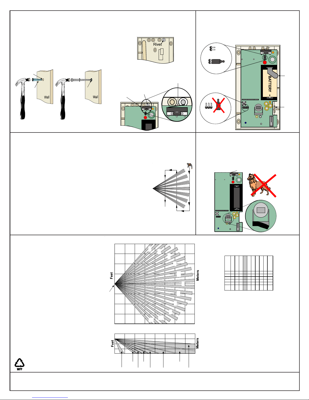
Step 6. If the wall tamper is used:
a. Remove the wall tamper knockout as
shown in Step 5.
b. Using the detector base as a guide, drill a 4.8 mm
(3/16 in.) hole into the wall.
c. Insert the wall anchor into the hole and tap gently
into place. Then place the rivet into the anchor and
tap into place.
d. When mounting the base, make
sure the rivet protrudes through
the correct hole.
Step 7. Select the Wall Tamper Jumper.
Step 8. Snap the board into the clip so the
notch aligns with the tab on the clip.
Step 9. Remove the pull tab to energize the
detector.
Wall Tamper
Enabled
4.8 mm
(3/16 in.) hole
Wall Anchor
Tap Wall Anchor
in place with
hammer.
Rivet
Wall Anchor
Tap R i v e t
in place with
hammer.
e. When mounting the circuit board,
the rivet must be over the Tamper
Switch Arm.
Ta mp er
Switch
Rivet
Switch Arm
4.0 Walk Test
Perform the Walk Test at the time of installation and annually thereafter.
a. Remove and replace the detector cover to enable the LED and place the detector in Walk Test
Mode for 90 seconds. If motion is detected, the detector remains in Walk Test Mode until a
90-second quiet period (no motion detected) occurs.
b. Walk test across the coverage pattern as shown in the diagram.
The edge of the coverage is determined by activation of the LED.
c. Walk test the unit from both directions to determine the boundaries.
d. If the desired range cannot be achieved, make sure the board is properly
positioned on the baseplate. Try angling the unit up or down when using
the optional swivel mount.
The RF940U infrared detector contains an environmental stabilization circuit
that requires approximately 3 minutes after initial power-up to warm up.
During this time, the detector LED blinks once per second and the detector
does not respond to any movement. After warm up, the detector must not see any movement for 2
seconds to complete stabilization. Rapid LED flash indicates Walk Test Mode is about to end unless
an alarm occurs.
Wall Tamper
Disabled
No Jumpers
Pull
Ta b
Locking
Ta b
5.0 Look-Down Zone
For non-pet applications only.
If look-down is desired, peel away the mask to enable
the Look-Down Zone. Do not remove the clear
plastic lens.
6.0 Coverage Patterns
Although generally not required, masking may
be desired to eliminate potential false alarm
sources by blocking individual zones (1 through
77 in the zone pattern), or to customize the
detection area.
The appropriate lens areas to be masked can
be derived from the lens diagram. For example,
covering the shaded area in the lens diagram
would block zones 5, 16, 27, 38, 49, 60, and 71
(i.e., one group of vertically layered zones).
Use an opaque material such as electrical tape
for masking.
© 2011 Bosch Security Systems, Inc.
130 Perinton Parkway, Fairport, New York 14450
www.boschsecurity.com
20
LookDown
20
10
0
0
0
0
0
Look-Down
67-77 45-55
56-66
Meters
1
2
10
11
Feet
Meters
34-44 23-33
12
6
3
1234567891011
4
5
6
0
7
12 22
23 33
34 44
45 55
56 66
67 77
Lens Diagram
(inside view)
8
9
Zone Pattern
6
(top view)
40
3
Zone Pattern
(side view)
0
12
12-22
1-11
3/11
RF940U Installation Instructions
P/N: F01U070611-07 Page 2
 Loading...