

Bosch RF940E Installation Manual
© 2011 Bosch Security Systems, Inc.
F.01U.249.034 | 01 | 2011.7 | 1
Gently insert a fl at-bladed screw-
driver into notch for the section you
wish to remove, and then lift on the
section to unhinge.
Installation
1
NOTICE:
Do not twist.
a) Remove the board from the case by pressing the mounting tabs toward
the side of the case and gently lifting the board.
b) Punch out appropriate holes in the mounting plate (for surface or corner applications). For optional swivel mount bracket, see instructions that
come with the bracket.
NOTICE: To avoid possible circuit board damage, use only the mounting
hardware provided in the appropriate punch-out mounting holes.
c) In non-pet applications only, if look-down is desired, peel away the lookdown mask. Do not remove the clear plastic lens.
d) Mount the detector between 2.3 m and 2.7 m high.
6.5 ft.
(2 m)
Peel away the mask.
2
Mask Removal for non-pet applications
Specifi cations
General
- Dimensions (HxWxD): 11.2 cm x 6.5 cm x 4.4 cm
(4.4 in. x 2.4 in. x 1.7 in.)
- Coverage Area: 12 m x 12 m.
- Operating temperature range of 0°C to +49°C (+32°F to +120°F).
- Relative humidity range of 0% to 95% (non-condensing).
- Maximum RF Power: less than 10mW.
- Operating Voltage: Suplied by two 3 VDC lithium batteries.
- Battery Life: approxiately 5 years under normal operation
conditions using the recommended battery types.
- Recommended Battery Types: Duracell DL123A, Energizer
EL123AP, or Panasonic CR123A.
- Compatible Receivers: RF3212E, RF3222E, or RF3224E.
- Compliance: CE 0165 - this device complies with EN 300683,
EN 300220, and 89/336/EEC.
- Options: B335 Low Profi le Swivel Mount Bracket (the use of
brackets may reduce range and increase dead zone areas)
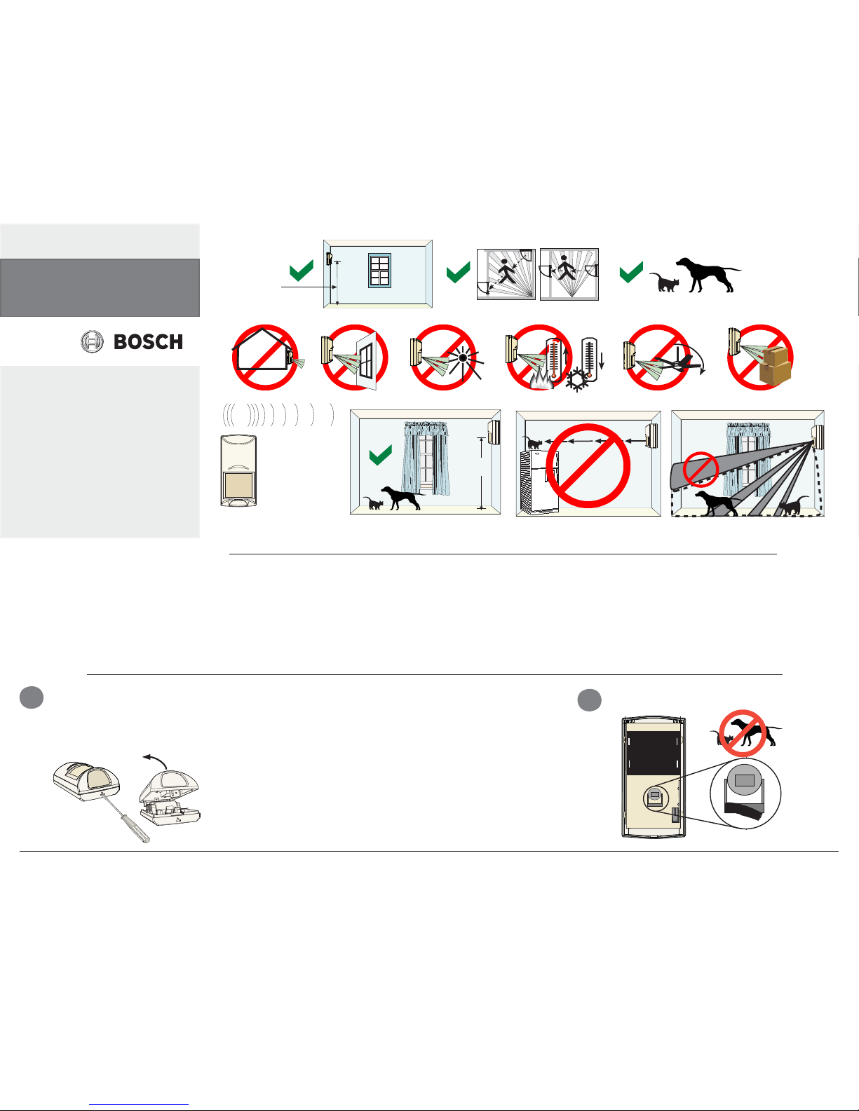
Mount the detector
2 m (6.5 ft) above the fl oor.
Do not point where
pets can climb.
The upper areas are
not pet immune.
RF940E Series Wireless
Passive Infrared Detector
Intrusion Detector with
Pet Immunity
en Installation Guide
Reading Bosch Security Systems, Inc.
Product Date Codes
For Product Date Code information, refer to the
Bosch Security Systems, Inc. Web site at:
http://www.boschsecurity.com/datecodes/.
Notice:
Batteries must not be disposed of in household
waste. Dispose of batteries in suitable collection
points. For futher information refer to
http://boschscurity.com/standards
Pet Friendly
1 dog ≤ 13 kg
(28 lb), or up to
two cats
1
Receiver Range:
300 m (984 ft)
Recommended:
100 m (300 ft)
2,2 m - 2,75 m
(7.5 ft - 9 ft)
Recommended:
2,2 m (7.5 ft)
© 2011 Bosch Security Systems, Inc. 130 Perinton Parkway Fairport, NY 14450
F.01U.249.034| 01 | 2011.7 | 2
Do not mount the
magnet fl ush with
the wall. A small
amount of adhesive
is rcommended to
keep the magnet in
place.
9 mm
65 mm
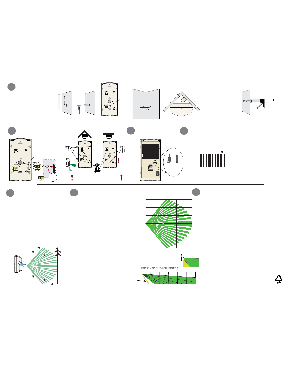
3
If wall tamper is desired:
Determine the location
of the detector. Measure
65 mm from the center
of the detector and mark
the spot on the wall. Drill
a 9 mm hole in the wall.
Corner Mounting:
Tap the magnet into the wall.
Wall
Tamper
Magnet
Location
Top V iew
10 mm
10 mm
Top of base
65 mm
9 mm
Surface Mounting:
Leveling
Mounting
Battery Installation
Pattern Testing
Final Testing
Programming your Control/Communicator Panel
0 m
20 ft
6 m
4 m
2 m
0 m
2 m
4 m
6 m
12 m
10 m
8 m6 m
4 m
2 m
20 ft
13 ft
7 ft
0 ft
7 ft
13 ft
0 ft 7 ft 13 ft 20 ft 26 ft 33 ft 40 ft
4
Circuit
Board
Mounting
Brackets
DO NOT OVERTIGHTEN THE
MOUNTING SCREWS
Wall
Tamper
No
Tamper
0 m
6 m
8 m
10 m 12 m
4 m2 m
26 ft 33 ft 40 ft
0 ft
7.5 ft
8.8 ft
0 m
2.3 m
2.7 m
0 ft
7 ft
13 ft
20 ft
Remove
masking for
Look-Down
5
Set the Wall Tamper
jumper.
6
There is a two part ID sticker located on the back of the
cover of the RF940E. You will need the number off this
sticker to program this device into the system.
See your Panel’s Wireless Reference Guide
for programming information for wireless-type
ID Number
167770187
167770187
The batteries are not installed in
the detector when it is shipped.
When installing the batteries it
is necessary to observe proper
polarity or the sensor may not
function.
When the batteries are installed,
wait at least 5 minutes before
activating the Walk Test Mode.
The LED will stop fl ashing when
the detector is ready to test (the
sensor requires “lack of motion”
to stabilize on startup).
7
8
Remove and replace cover to activate a
90-sec Walk Test Mode. During this Test
Mode, any activity in the sensor’s coverage pattern will cause a transmitted
alarm and LED activation. Each alarm will
also extend the Test Mode for an additional 90-sec. Walk Testing should be
done across the coverage pattern. The
edge of the coverage pattern is determined by the fi rst fl ash of the LED. This
may change slightly depending upon
the sensitivity setting. Walk Test the
unit from both directions to determine
the pattern boundaries.Although generally not required, if masking is desired,
the lens diagram shows the appropriate
areas to be masked. Use an opaque material (such as, electrical tape) to mask the
desired areas.
NOTICE: Excessive use of the Walk Test
Mode may reduce battery life. Use only
for initial setup and
maintenance testing.
While the detector is in the Walk Test Mode,
turn on all heating and air conditioning sources
which would normally be active during the
protection period. Stand away from the sensor
and outside the coverage pattern and watch for
alarms. After setup and tests are completed,
and there has been no activity in the sensor’s
coverage pattern for approximately 90-sec, the
LED will fl ash to indicate that the Walk Test
mode is ending.
NOTICE: In the normal operating mode, an
alarm can be transmitted only after three (3)
minutes have passed since the previous alarm
restoral. This 3 minute lockout time reduces unnecessary RF transmissions in high traffi c areas
thereby extending battery life.
Maintenance
At least once a year, the range and coverage
should be verifi ed for proper operation. To
assure daily operation, the end user should be
instructed to walk through the far end of the
coverage pattern to verify an alarm output prior
to arming the system.
9
Top View
 Loading...