

Bosch RF835 Installation Manual
© 2012 Bosch Security Systems, Inc. F01U254569 | 02 | 2012.11 | 1
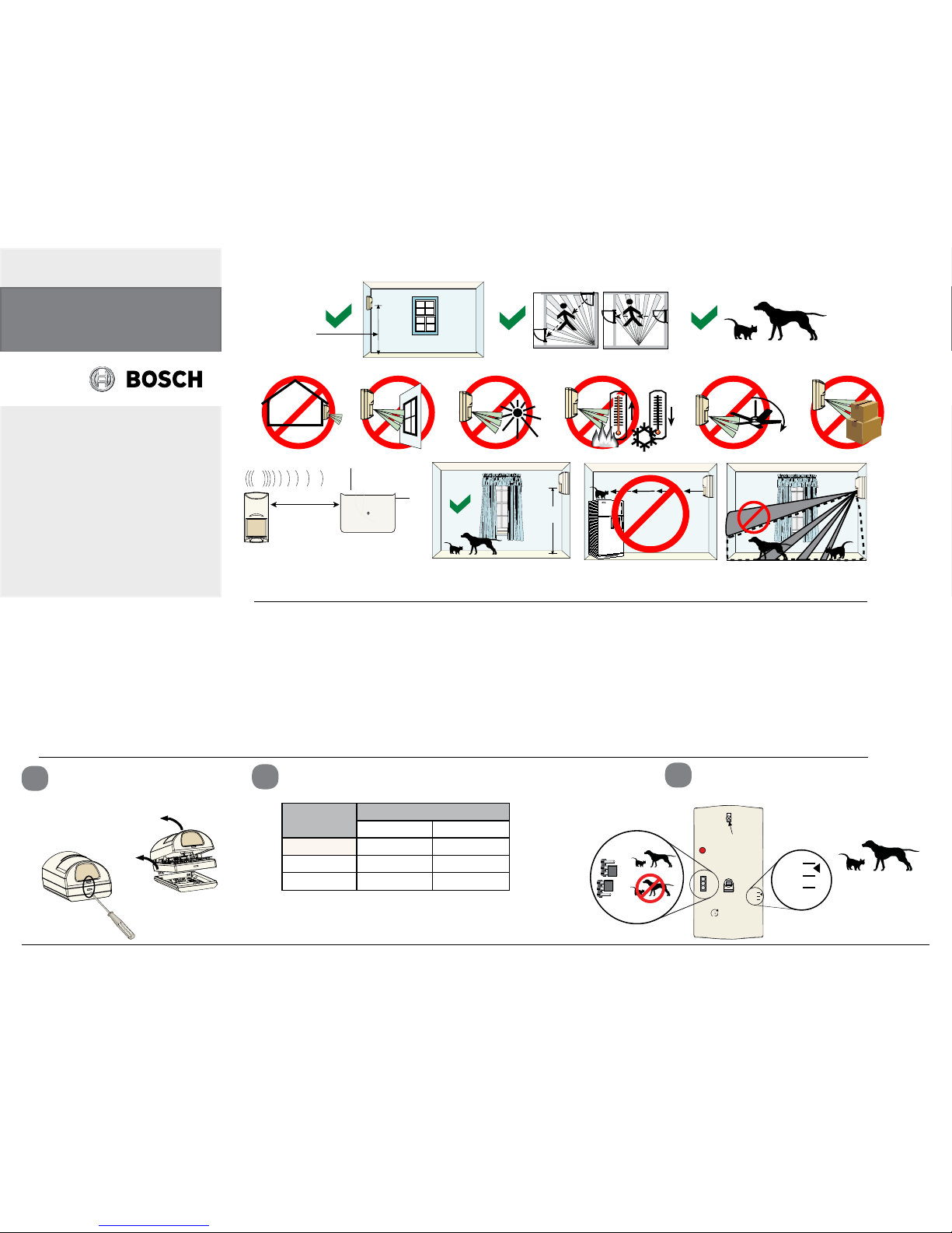
Installation Gently insert a flatbladed screwdriver into notch for
the section you wish to remove, and
then lift on the section to unhinge.
1
NOTICE:
Do not twist.
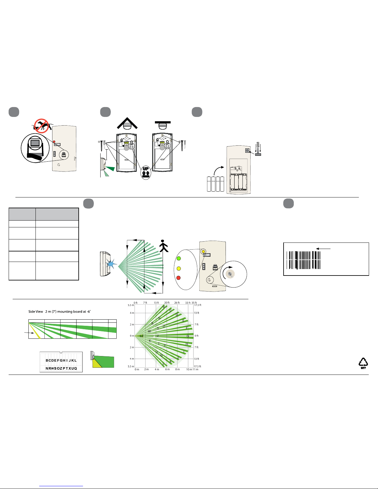
NOTICE:
The mounting height must be 2 m (6.5 ft) and the vertical
angle must be set at -5° for installations containing pets.
Mounting
Height
Range
6.1 m (20 ft) 10.7 m (35 ft)
2 m (6.5 ft) - 7 ° - 5 °
7.0 ft (2.1 m) - 9 ° - 6 °
8.0 ft (2.4 m)
- 10 ° - 7 °
2
3
Height and Adjustment
Loosen the Vertical Adjust Screw. Adjust the board to the desired angle.
Choose mounting height and desired range and set the vertical angle.
INT
STD
Vertical
Adjust
Screw
- 6
- 10
- 6
- 10
MW
MIN
MAX
For pet immune
applications, adjust
the angle to -5.0.
INT
STD
INT
STD
PIR Sensitivity Selection Pins
Set the PIR Senstivity Vertical adjusing
screw must be securely tightened after setting the angle.
Reading Bosch Security Systems, Inc.
Product Date Codes
For Product Date Code information, refer to the
Bosch Security Systems, Inc. Web site at:
http://www.boschsecurity.com/datecodes/.
Notice:
Product must be installed in accordance with
NFPA70, Local Authorities Having Jurisdiction
(AHJ’s) and all local codes.
Specifications
General
• Dimensions (HxWxD): 13.9 cm x 7.2 cm x 6.9 cm (5.4 in. x 2.8 in. x 2.7 in.)
• Power supplied by four 1.5V AA Alkaline Batteries. Recommended Batteries: Panasonic AM-3,Duracell MN1500, or PC1500 Energizer E91.
• Typical current draw is 100 μA with the LED disabled. The LED is automatically disabled except during walk tests.
• Typical battery life is two to three years.
• Operating temperature range of 0°C to +49°C (+32°F to +120°F).
• Relative humidity range of 0% to 95% (0% to 85% UL installation).
• Microwave Frequency: 10.525 GHz.
• RF Transmit Frequency: 304.00 MHz.
RF Transmitter
• Integral RF transmitter capable of transmitting 150
m (500 ft) in open air. (Actual acceptable transmitter range should be verified for each installation). In
normal operation, it is recommended that the RF835
be within 30 m (100 ft) of the receiver.
• Transmits low battery reports and tamper reports to
the control panel.
• Transmits supervisory signal to the control panelevery
65 minutes.
• UL Listed for residential use only.
TriTech Motion Sensor
• Coverage area 10.7 m by 10.7 m (35 ft by 35 ft).
• Internal coverage pointability -4° to -10° Vertical.
• Field selectable sensitivity options of Standard and
the more sensitive setting of Intermediate.
• Three minute transmitter lockout time after alarm
extends battery life.
• Timed Walk Test Mode automatically disables LED
after setup to extend battery life.
• Cover activated Tamper indication. Optional wallactivated Tamper is included.
Mount the detector
2 m (6.5 ft) above the floor.
Do not point where
pets can climb.
The upper areas are
not pet immune.
Receiver
1
Receiver Range: 150 m (500 ft)
Recommended: 30 m (100 ft)
2.0 m - 2.4 m
(6.5 ft - 8 ft)
Recommended:
2.0 m (6.5 ft)
Pet Friendly
≤ 45 kg (100 lb)
Not tested by UL
RF835 Series Wireless
Tri Tec h PIR/Microwave
Intrusion Detector with
Pet Immunity
en Installation Guide
Optional Brackets:
B328, B335, B338, B800
Batteries must not be disposed of in household
waste. Dispose batteries at suitable collection
points. For further information refer to
http://boschsecurity.com/standards.
© 2012 Bosch Security Systems, Inc. 130 Perinton Parkway Fairport, NY 14450 F01U254569 | 02| 2012.11 | 2
FCC and IC Compliance Notice
This device complies with Part 15 of the FCC Rules. Operation is subject to the
following two conditions: (1) This device may not cause harmful interference,
and (2) this device must accept any interference received including interference
that may cause undesired operation. This device complies with Industry Canada
licence-exempt RSS standard(s).
Le présent appareil est conforme aux CNR d’Industrie Canada applicables aux appareils radio exempts de licence. L’exploitation est autorisée aux deux conditions
suivantes : (1) l’appareil ne doit pas produire de brouillage, et (2) l’utilisateur de
l’appareil doit accepter tout brouillage radioélectrique subi, même si le brouillage
est susceptible d’en compromettre le fonctionnement.
Under Industry Canada regulations, this radio transmitter may only operate using
an antenna of a type and maximum (or lesser) gain approved for the transmitter
by Industry Canada.
To reduce potential radio interference to other users, the antenna type and its
gain should be so chosen that the equivalent isotropically radiated power (e.i.r.p.)
is not more than that necessary for successful communication.
Conformément à la réglementation d’Industrie Canada, le présent émetteur radio
peut fonctionner avec une antenne d’un type et d’un gain maximal (ou inférieur)
approuvé pour l’émetteur par Industrie Canada. Dans le but de réduire les
risques de brouillage radioélectrique à l’intention des autres utilisateurs,
il faut choisir le type d’antenne et son gain de sorte que la puissance
isotrope rayonnée équivalente.
4
Uncover the Look Down Lens
NOTICE:
In non-pet applications only, If look-down
is desired, peel away the look-down mask.
Do not remove the clear plastic lens.
5
Mount the Detector Base
NOTICE:
The Wall Tamper cannot be used in corner mount installations or when using the
swivel bracket
.
6
Install the Battery
The batteries are not installed in
the detector when it is shipped.
When installing the batteries it is
necessary to observe proper polarity or the sensor may not function.
7
LED
Condition
Cause
Steady Red Unit Alarm
Steady
Yellow
Microwave Activation
(Walk Test)
Steady
Green
PIR Activation
(Walk Test)
Flashing
Red
Warm-Up Period
After Power-Up
Flashing
Red
(four-pulse
sequence)
Microwave or PIR
Failure
Replace Unit
If the Wall Tamper is desired, gently
press the spring onto the tapered shaft.
Do not force it down onto the shaft. As
you place the unit onto its base, be sure
the spring extends through the knock-out
to the wall.
When the batteries are installed, wait at
least 5 min before activating the Walk
Test Mode. The LED will stop flashing
when the detector is ready to test (the
sensor requires “lack of motion” to stabilize on startup). Refer to LED Conditions
chart.
LED Conditions:
Walk Test the Detector
Perform this test at the time of installation and monthly thereafter. To ensure continual daily operation, the end user should be instructed to walk through the far end of
the coverage pattern. This ensures an alarm output prior to arming the system.
Remove and replace the cover to start a 90-sec Walk Test Mode.
During this Test Mode, any activity in the sensor’s coverage pattern will cause a transmitted alarm and LED activation. Each alarm will also extend the Test Mode.
Watch for the yellow LED to indicate the edges of the Microwave pattern. Adjust as
necessary.
8
Program the Control Panel
There is a two-part ID sticker located on the housing of the RF835.
You will need the number on this
sticker to program the Detector
into the control panel. Refer to your
panel’s Programming Guide for
programming information on wireless type devices.
ID Number
167770187
167770187
NOTICE:
Insert security screws after testing to
prevent covers from separating.
NOTICE:
The protective zone
is the area where
the PIR and
Microwave
technologies
overlap.
NOTICE:
Masking only
eliminates the PIR
portion of the
coverage and has no
effect on the
Microwave pattern.
Green =
PIR
Yellow =
MW detect
Red =
Alarm
INT
STD
MIN
MAX
Set the adjustment
as low as possible
for proper catch
performance
MIN
MAX
Coverage Patterns
Masking Lens
Remove
masking for
Look-Down
LZ
W-X
R-U, Z
N-Q
B-L
0 m
2 m 10 m8 m
6 m
4 m 11 m
7.8 ft
7 ft
0 ft
0 ft 35 ft33 ft
26 ft
20 ft
13 ft
7 ft
2.4 m
2 m
0 m
Top View
 Loading...