

Page 1
RF3405E
Installation Instructions
EN
Wireless (RF) Inertia
Transmitter
Page 2
RF3405E | Installation Instructions |
3
4
5
P1
P2
P3
P4
P5
P6
INERTIA LOOP
BATTERY
NeverReady Batteries, Inc.
Lost Power, NV
1
2
10 mm (0.39 in.) maximum
1
OK
12 mm (0.47 in.) nominal
3
2
OK
12 mm (0.47 in.) nominal
1.0 General Information
EN | 2
Installation Instructions
for the RF3405E
Wireless (RF) Inertia T ransmitter
1.0 General Information
The RF3405E Inertia Transmitter is a magnetic and dry
contact wireless transmitter with a built-in inertia sensor
used for monitoring doors, windows, or other dry
contact devices.
The inertia transmitter is equipped with internal reed
contacts for use with an external magnet assembly and
an inertia sensor for detecting shock. The transmitter
can also accept a dual EOL resistor supervised dry
contact input from an external device. A cover/wall
tamper switch is provided.
Supervision is provided by periodically transmitting a
supervisory signal to the receiver every 13 minutes if
there is no other activity. All transmissions from the
RF3405E send battery status information.
2.0 Mounting
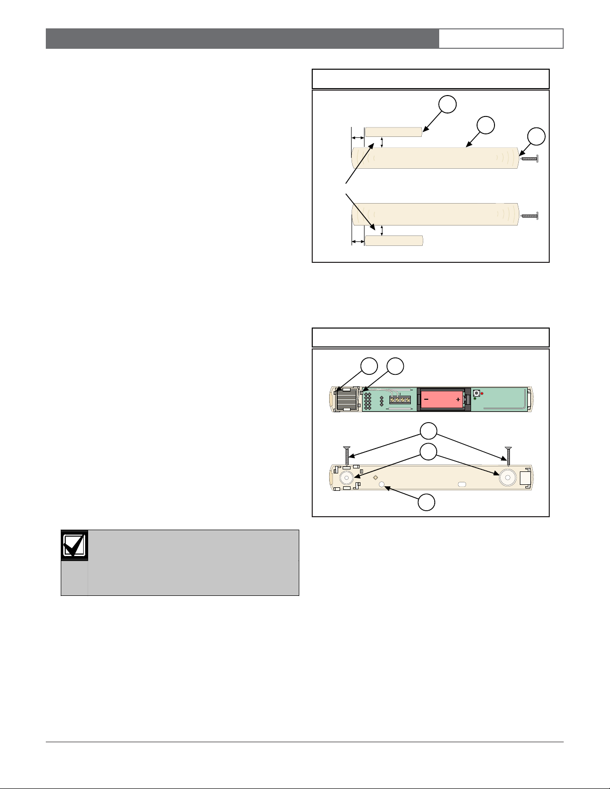
Figure 1: Magnet Location
1 - Inertia transmitter
2 - Magnet
3 - Cover screw location
Figure 2: Base Plate
2.1 Mounting Considerations
2.2 Mounting the Transmitter
Refer to Figure 2 when mounting the inertia transmitter.
1. Position the base plate over the desired location. If
2. If the transmitter is already installed, remove the
• The maximum range of the inertia transmitter, in
open air, is approximately 300 m (98 ft.).
Typically, keep this transmitter within 100 m
(328 ft.) of the receiver to which it is assigned.
• Mounting the inertias transmitter on metal
surfaces may reduce its RF range. Mounting it on
ferrous metal (iron or steel) surfaces may affect
the operation of the internal magnetic contact.
• Mount the inertia transmitter on the door or
window frame and mount the magnet assembly
on the moving portion.
The magnet assembly must be oriented as
shown in
Figure 1
. The magnet must be no
farther away than 10 mm (0.39 in.) from the
body of the inertia sensor for normal
operation.
connecting to external contacts, position the
mounting plate so the wiring passes through the
wire entrance (callout #5).
inertia sensor bracket by pressing the inertia sensor
tab (callout #1).
1 - Inertia sensor bracket
2 - Circuit board tab
3 - 13 mm (0.51 in.) panhead mounting screws
4 - Base mounting holes
5 - Wire entrance
3. Remove the circuit board by pressing the circuit
board tab (callout #2).
4. Mount the base plate using the 13 mm (0.51 in.)
panhead screws (callout #3) through the base
mounting holes (callout #4).
5. Refer to Section 2.4 Mounting the Inertia Sensor if the
inertial sensor is used.
Bosch Security Systems | 8/03 | 47128C
Page 3
RF3405E | Installation Instructions |
Orientation of the Inertia sensor is critical to
the proper operation of the inertia detection
function.
An UP arrow, imprinted on the body of this
sensor, must always point upwards when
mounted in the transmitter base.
2.0 Mounting
EN | 3
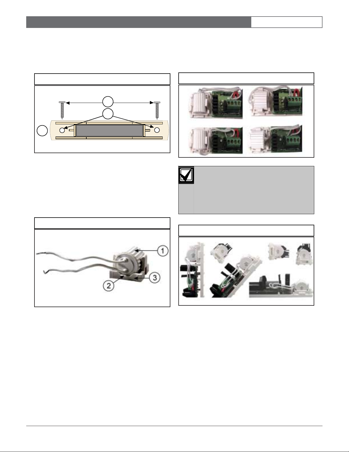
2.3 Mounting the Magnet (if used)
Position the magnet base plate over the desired location,
using the mounting configuration shown in Figure 1.
Figure 3: Magnet Base Plate
2
3
1
1 - Magnet assembly
2 - 16 mm (0.63 in.) flathead screws
3 - Magnet assembly mounting holes
2.4 Mounting the Inertia Sensor
1. Mount the inertia sensor so the wires are over the
notched portion of the base plate (see Figure 4).
2. Press the inertia sensor all the way into the bracket.
3. You can mount the inertia sensor in four different
positions on the base plate (see Figure 5). Route the
wiring in a way that prevents crimping by the cover.
Figure 5: Inertia Sensor Mounting Positions
Figure 4: Inertia Sensor Wire Placement
1 - Inertia sensor
2 - Notch in base bracket
3 - Inertia sensor base bracket
Figure 6: Inertia Sensor: Point Up
Bosch Security Systems | 8/03 | 47128C
Page 4

RF3405E | Installation Instructions |
1
2
P1
P2
P3
P4
P5
P6
P1
P2
P3
P4
P5
P6
1
2
3.0 Wiring
EN | 4
3.0 Wiring
The RF3405E can be wired for an inertia
sensor or an external contact, but not both.
3.1 Wiring for the Inertia Sensor
Figure 7: Inertia Sensor Wiring
1
P1
P2
P3
P4
P5
1 - Inertia sensor wires
2 - Wire jumper across loop terminals
3.2 Wiring for the External Contact
INERTIA LOOP
P6
4.0 Jumper Settings
4.1 Reed Switch Enable (Jumper P2)
If Jumper P2 is removed, the internal magnetic reed
switches are enabled (see Figure 9).
Figure 9: P2 Reed Switch
2
1 - Jumper on disables internal reed switches
2 - No jumper enables internal reed switches
4.2 Setting for Inertia or External Contact
(Jumper P6)
The detector can be set to monitor the internal inertia
sensor or a set of external contacts (see Figure 10).
Figure 8: External Contact Wiring
1
P1
INERTIA LOOP
P2
P3
P6
P4
P5
2
1.5 kΩ
2.2 k
Ω
1 - Wire jumper across inertia terminals
2 - Length of contact loop can be up to 6 m (20 ft.)
3 - Normally closed (NC) contact
The wire jumper in the Loop terminals must
be ON when using the Inertia function. The
wire jumper in the Inertia terminals must be
ON when using the External contact function.
Figure 10: Set Inertia or External Contact
3
1 - External contact
2 - Inertia sensor
Bosch Security Systems | 8/03 | 47128C
Page 5

RF3405E | Installation Instructions |
4.0 Jumper Settings
EN | 5
4.3 Minor and Gross Attack (Jumper P1)
If Jumper P1 is installed, the inertia detector reacts only
to Gross Attacks (major movement). Minor movement
or a series of taps does not activate the inertia detector.
Jumper P4 and Jumper P5 settings determine the
sensitivity of the inertia detector to Gross Attack (see
Section 4.5).
Jumper P6 must be set for Inertia to enable these
settings. See Figure 11.
Figure 11: P1 Attack Monitor
1
P1
P2
2
P3
P6
P4
P5
1 - No jumper for minor and gross attacks
2 - Jumper on for gross attack only
4.4 Pulses for Minor Attack (Jumper P3)
The setting of Jumper P3 determines the number of
repetitive pulses needed to activate the inertia detector
to a Minor Attack.
If Jumper P3 is removed, the inertia detector reacts to
four repetitive pulses. This setting is only valid if
Jumper P1 is set for Minor Attack and Jumper P6 is set
for Inertia. See Figure 12.
4.5 Sensitivity for Gross Attack
(Jumpers P4 and P5)
These settings are valid only if Jumper P6 is set for
Inertia.
Figure 13: Gross Attack Jumper Settings
1
2
3
4
P4
P4
P4
P4
1 - Low sensitivity
2 - Low/Medium sensitivity
3 - Medium/High sensitivity
4 - High sensitivity
P5
P1
P2
P3
P5
P5
P5
P4
P5
P6
Figure 12: Attack Pulses
1
2
1 - Jumper on for eight repetitive pulses
2 - No jumper for four repetitive pulses
Bosch Security Systems | 8/03 | 47128C
P1
P2
P3
P6
P4
P5
Page 6

RF3405E | Installation Instructions |
Dimensions
(H x W x D)
Transmitter: 2.7 cm x 2.4 cm x 16.9 cm
(1.06 x 0.94 in. x 6.65 in.)
Magnet: 1.9 cm x 1.3 cm x 16.9 cm
(0.75 in. x 0.51 in. x 2.36 in.)
Operating
Temperature
-20°C to +60°C (-4°F to +151°F);
0% to 95% relative humidity
(non-condensing)
Frequency
Band
433.42 MHZ
Maximum RF
Power
Less than 10 mW
Operating
Voltage
Supplied by a 3 VDC lithium battery
Battery Life
A minimum of 3 years under normal
operating conditions with recommended
battery types (2 years if using the inertia
sensor).
Recommended
Battery Types
Duracell DL123A
Energizer EL123AP
Panasonic CR123A
Compatible
Receiver
RF3227E
Supervisory
Internal
13 minutes nominal
5.0 Installing the Battery
EN | 6
5.0 Installing the Battery
Be sure to observe the battery polarity (see Figure 14).
Figure 14: Battery Installation
NeverReady Batteries, Inc.
Lost Power, NV
P1
INERTIA LOOP
P2
P3
P6
P4
P5
6.0 Programming the Panel
There is a two-part ID sticker located on the housing of
the RF3405E (see Figure 15). You need the number on
this sticker to program the inertia transmitter into the
control panel.
Refer to the panel Programming Guide for programming
information on wireless type devices.
Figure 15: ID Sticker
8.0 Specifications
Table 1: Specifications
Bosch Security Systems | 8/03 | 47128C
ID: XXXXXXXXX
YYYYYYY
!
ID: XXXXXXXXX
7.0 Testing the Detector
Once the detector is mounted, you can place it in Test
Mode for 15 minutes by opening and then closing the
detector cover, or by pushing both tamper springs then
releasing one or both of them (if the cover is off). The
LED flashes once (and then continues flashing dimly) to
indicate it is in Test Mode. During the testing time, the
LED flashes twice each time a Minor Inertia Attack
occurs, a magnetic contact changes state (open or close),
or any time the external contact (if used) changes state.
The LED flashes three times for a Gross Inertia Attack.
If any jumpers are changed during Test Mode, the LED
flashes once to indicate the change.
Page 7

RF3405E | Installation Instructions |
EN | 7
Notes:
Bosch Security Systems | 8/03 | 47128C
Page 8

Bosch Security Systems
130 Perinton Parkway
Fairport, NY 14450-9199 USA
www.boschsecurity.us
Customer Service: (800) 289-0096
Technical Support: (888) 886-6189
© 2003 Bosch Security Systems
Subject to change | Printed in the USA
47128C
 Loading...