

Bosch RF3224 Installation Instructions Manual

Installation Instructions for the
1
RF3224 RF Receiver
1.0 General Information
The RF3224 RF Receiver allows the use of wireless
devices when using the D6412 Control Panel.
2.0 Specifications
Table 1: Specifications
2. Press the latch to remove the inner cover (see Figure 2).
Figure 2: Removing the Inner Cover
1
GY
R
B
ADDR
2
Dimensions
(H x W x D)
Operating
Temperature
Frequency
Power
Requirements
Compatible
Control Panels
Compliance
10.8 cm x 15.2 cm x 3.1 cm
(4.25 in. x 6.0 in. x 1.2 in.)
0°C to +65°C (+32°F to +150°F)
For UL Listed requirements, the temperature
range is 0°C to +49°C (+32°F to +120°F)
304.00 MHz
12 VDC, 30 mA, nominal
D6412, D4412, DS7240, and DS7220
This device complies with Part 15 of the FCC
1 - Cover tamper
2 - Press latch to remove inner cover.
3. Move the wall tamper jumper as shown in Figure 3.
Figure 3: Wall Tamper Jumper
1
GY
R
B
ADDR
Rules and the RSS-210 of Industry and
Science Canada. Operation is subject to:
•
The device not causing harmful
interference, and
•
The device accepting any interference
received, including interference that may
cause undesirable operation.
Changes or modifications not expressly
approved by Bosch Security Systems can void
the user’s authority to operate the equipment.
1 - Wall tamper jumper
2 - Wall tamper disabled (default position)
3 - Wall tamper enabled (jumper left on pin for storage only)
4. Replace the inner cover.
5. Place the spring from the hardware packet over the
shaft of the tamper switch located on the back of the
2
3
receiver (see Figure 4).
3.0 Mounting
3.1 Mounting Considerations
• Whenever possible, mount the receiver centrally to all
wireless sensors.
• Mount the receiver vertically with at least 25 cm
(10 in.) clearance above it for the antennas.
• Avoid mounting the receiver in areas with significant
metal or electrical wiring, such as furnace rooms and
utility rooms. If unavoidable, mount the receiver with
the antennas extending above any metal surface.
• Avoid mounting the receiver in areas where it may be
exposed to moisture.
• Reception distances are generally improved with
higher mounting locations and with no metal objects
near the antennas.
3.2 Wall Tamper Setup
To enable the wall tamper switch, follow the procedure
below. If not using the wall tamper, go to Section 3.3
Mounting the Receiver.
1. Remove the receiver's outer cover and set it aside (see
Figure 1).
Figure 1: Removing the Outer Cover
1
1 - Insert screwdriver here and press in.
Figure 4: Installing the Tamper Spring
1 - Rear of receiver
Note: Gently press the spring onto the tapered shaft.
Do not
force it down onto the shaft.
3.3 Mounting the Receiver
1. Determine the mounting location of the receiver.
2. If not already done, remove the outer cover from the
receiver and set it aside (see Figure 1).
3. Place the receiver base on the wall at the desired
mounting location and mark the two mounting holes
(see Figure 5).
4. Drill holes and install anchors (supplied), if necessary.
5. Secure the receiver base to the wall with screws
(supplied).
6. Insert an antenna into the outside terminal on two of
the antenna connectors as shown in Figure 6. Tighten
screws to secure the antennas.
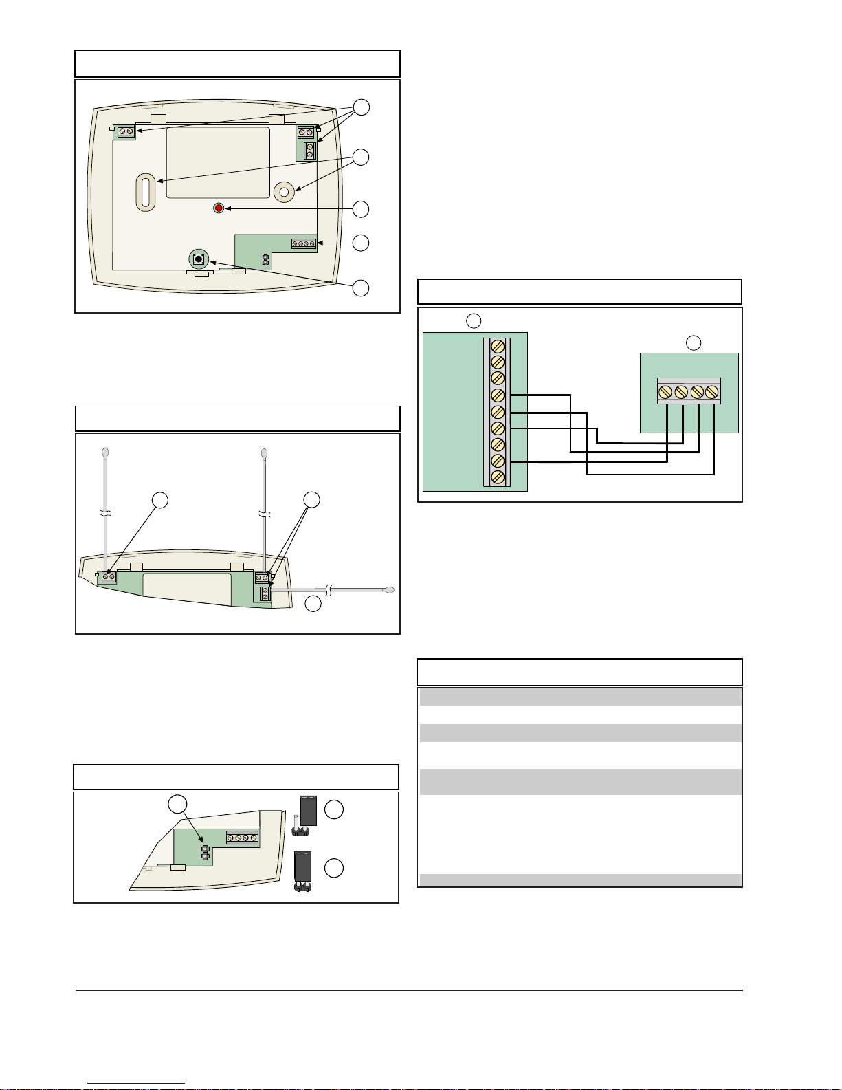
Figure 5: Receiver with Outer Cover Removed
R
ADDR
4.0 Wiring and Power Up
4.1 Wiring the Receiver to the Control Panel
1
2
3
GY
B
4
5
1. Disconnect power from the control panel.
2. Connect the D6412 Option Bus terminals to the
RF3224 receiver terminals as shown in Figure 8, using a
minimum of 22 AWG (0.8 mm diameter) wire.
The wire length between the receiver and the control
panel should not exceed 300 m (1000 ft.). Adding
supplementary devices to the bus may reduce the
maximum distance. Shielded cable is not required. Do
not use twisted pair wire.
Note: Fire systems installed under NFPA 72 or UL Listed
Fire Systems require the use of #18 AWG (1.2 mm) or larger
wire.
Figure 8: Connecting to the Option Bus
1 - Antenna connectors
2 - Mounting holes
3 - LED
4 - Bus and power connector
5 - Cover tamper switch
Figure 6: Connecting Antennas
1
2
3
1 - Mount one antenna here and point it upwards.
2 - Mount second antenna at one of these locations.
3 - Preferred location (provides polar diversity)
3.4 Setting Receiver Options
Note: Changing these settings requires removing the power to
the receiver and then reapplying for the changes to take affect.
Set the receiver address option as required (see Figure 7).
Figure 7: Address
1
R
GY
B
ADDR
2
3
1
2
RBGY
GRN
YEL
BLK
RED
1 - D6412
2 - RF3224
3. Replace the outer cover.
4. Apply power to the control panel. The red LED at the
center of the receiver illuminates.
4.2 LED Status
Table 2 describes the status of the receiver based on the
LED condition.
Table 2: LED Status
LED Condition Meaning
On The receiver functions normally.
Off A power failure occurred or the receiver is not
wired correctly.
Turns on
Momentarily
Flashes
Rapidly
The receiver acknowledged receiving a
message from a compatible transmitter.
The receiver is being programmed with zone
and transmitter IDs from the D6412 Control
Panel. This condition occurs upon initialization
(power up) of the system or when new zone
information is programmed into the system. The
rapid flashing lasts for less than 1 minute.
1 - Address
2 - Receiver #1 (default). Jumper left on pin for storage only.
3 - Receiver #2
© 2003 Bosch Security Systems 40819E
130 Perinton Parkway, Fairport, NY 14450-9199 USA Installation Instructions
Customer Service: (800) 289-0096; Technical Support: (888) 886-6189
5.0 Panel Programming
For programming information, refer to the D6412 Control
Panel Reference Guide.
7/03
RF3224
Page 2 of 2
 Loading...