

Bosch RF3212E Installation Instructions Manual
Installation Instructions
for the
RF3212E RF Receiver
1.0 General Information
The RF3212E RF Receiver allows you to use wireless devices
when used with the EDM Solution Control/Communicator.
2.0 Specifications
• Dimensions (HxWxD): 10.8 cm x 15.2 cm x 3.0 cm
• Operating Temperature: 0°C to +65°C
• Frequency: 433.42 MHz
• Power Requirements: 12 VDC, 30 mA, nominal
• Compatible Control Panels: EDM Solution Ultima models
844, 862, 880
• Compliance: CE 0165 - This device complies
with EN 300683, EN 300220, and
89/336/EEC.
3.0 Mounting
3.1 Mounting Considerations
• The Receiver should be mounted in a central location in regard
to all wireless sensors, whenever possible.
• The Receiver should be mounted on a vertical surface with at
least 25 cm clearance for the antennas.
• Avoid mounting the Receiver in areas with significant metal or
electrical wiring; such as, furnace rooms and utility rooms. If this
is unavoidable, mount the Receiver with the antennas extending
above any metal surface.
• Avoid mounting the Receiver in areas where it may be exposed
to moisture.
• Reception distances are generally improved with higher
mounting locations and with no metal objects near the Antennas.
3.2 Wall Tamper Setup (Optional)
To enable the Wall Tamper Switch, follow the procedure below. If
the use of the Wall Tamper is not desired proceed to section 3.3.
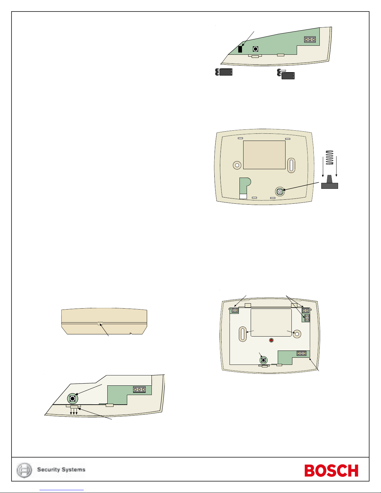
• Remove the Outer Cover of the Receiver (see Figure 1) and set
it aside.
Wall Tamper Jumper
-
+
DATA
PWR
Wall Tamper disabled
(Default Position)
Jumper left on pin for stor age only.
Wal l Tamp er enable d
Figure 3 - Wall Tamper Jumper
• Replace the Inside Cover.
• Place the Spring from the hardware packet over the shaft of the
Tamper Switch located on the back of the Receiver (see
Figure 4).
Rear of receiver
Figure 4 - Installing the Tamper S pring
NOTE:Gently press the Spring onto the tapered shaft. Do not force it
down onto the shaft.
3.3 Mounting the Receiver
• Determine the mounting location of the Receiver.
• If not already done, remove the Outer Cover from the Receiver (see
Figure 1) and set it aside.
• Place the Receiver base on the wall at the desired mounting location
and mark the two Mounting Holes (see Figure 5).
Antenna Connectors
Insert screwdriver here
and press in
Figure 1 - Removing the Outer Cover
• Remove the Inside Cover (see Figure 2) by pressing the Latch.
Cover Tamper
Press Latch
to remove Inside Cover
Figure 2 - Removing the Inner Cover
• Move the Wall Tamper Jumper as shown in Figure 3.
Mounting Holes
Cover
Tamper
Switch
-
+
DATA
PWR
Figure 5 - Receiver with Outer Cover removed
+
PWR
-
DATA
Bus and
Power
Connector
• Drill holes and install anchors (supplied) if necessary .
• Secure the Receiver base to the wall with screws (supplied).
• Insert an Antenna into the outside terminal on two of the Antenna
Connectors as shown in Figure 6. Tighten screws to secure the
Antennas.
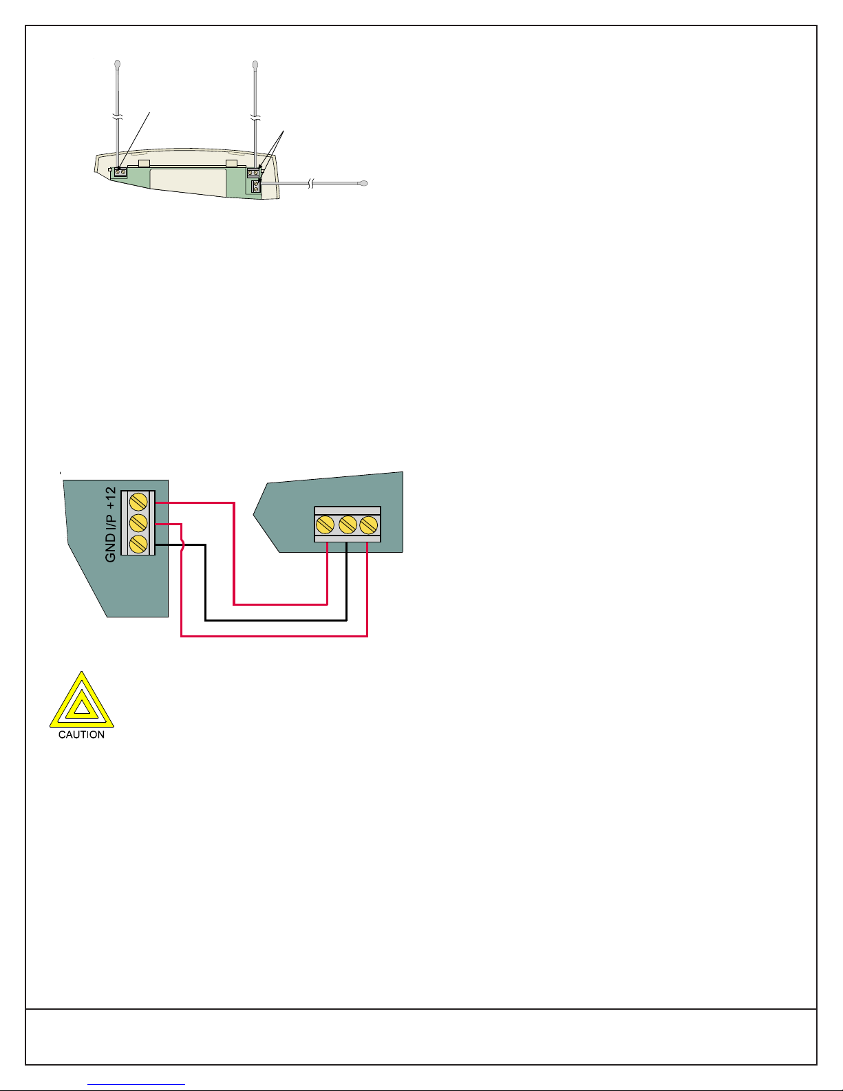
Use one
EDM Panel
One Antenna
must mount
here and point
upwards.
of these
locations
for the
second
Antenna
Preferred
Location
(provides polar
diversity)
Figure 6 - Connecting Antennas
NOTE: The remaining Antenna Connector and the remaining holes
in the used Antenna Connectors are not used.
4.0 Wiring and Power Up
4.1 Wiring the Receiver to the Control Panel
• Disconnect power from the Control Panel.
• Connect the Receiver Terminals to the Control Panel Terminals
as shown in Figure 7 using 0.8 mm diameter or larger wire. Wire
length between the Receiver and the Control Panel should not
exceed 300 meters.
• Replace the Outer Cover.
5.0 Panel Programming
For programming information, refer to the following Control Panel
Reference Guides:
Solution Ultima 844 Quick Reference Guide MA844Q
Solution Ultima 862 Quick Reference Guide MA862Q
Solution Ultima 880 Quick Reference Guide MA880Q
RF3212E
PWR
-
DATA
+
Figure 7 - Connecting to the EDM Panel
Do not connect the RF3212E to the Keypad Bus on
the EDM Panel.
• Apply power to the Control Panel. The red LED at the center of
the Receiver should light.
4.2 LED Status
The following describes the status of the Receiver based on the
LED condition.
LED on - The Receiver is functioning normally.
LED off - A power failure has occurred or the Receiver is
not wired correctly.
LED flashes - The Receiver acknowledged receiving an RF
signal from a compatible RF transmitter.
© 2004 Bosch Security Systems
130 Perinton Parkway, Fairport, New York, USA 14450-9199
Customer Service: (800) 289-0096; Technical Support: (888) 886-6189
03/04
RF3212E Installation Instructions
P/N: 42785E Page 2
 Loading...