

Bosch RF280E Installation Instructions Manual
RF280E Series
Installation Instructions
EN
Wireless (RF)
Photoelectric Smoke
Detectors
RF280E Series | Installation Instructions |
Trademarks
Trademarks
Chamber Check® is a registered trademark of Bosch
Security Systems in the United States.
1.0 Overview
The RF280E Series Photoelectric Smoke Detectors are
open-area wireless smoke detectors designed for use
with commercial fire protective signaling and household
fire warning systems.
For commercial and industrial installations, allow
spacing of 30 ft (9 m) between detectors.
An Alarm and Test LED flashes approximately every
26 sec to verify the detector has battery power and the
smoke sampling circuitry is functioning. The LED
flashes every 0.5 sec in an alarm, allowing the user to
verify individual detector alarms. The detector
automatically resets after 3 min if the alarm condition
no longer exists.
The detector can be manually reset by pressing the Test
button. If there is an alarm after the Test button is
pressed, the detector re-alarms in 20 to 30 sec. After the
alarm condition clears, the control panel alarm can be
cleared by a control panel reset command.
Supervision is provided by transmitting a low power
level signal to the receiver every 13 min if there is no
other activity. All transmissions from the RF280E Series
send battery status information to the control panel.
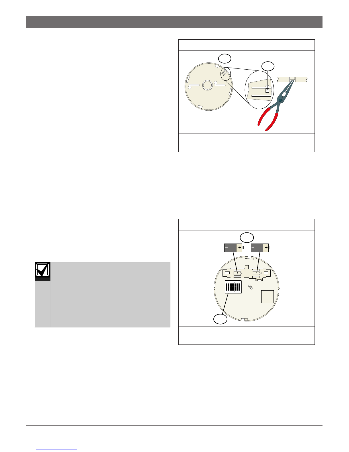
Figure 1: Modifying the Lock-In Tab
1
2
1 - Base locking tab
2 - Lock-In feature. Break away to access.
3. Remove the detector from the mounting plate by
twisting the base counterclockwise.
4. Install the mounting plate in the desired location,
and do not attach the detector to the mounting plate
at this time.
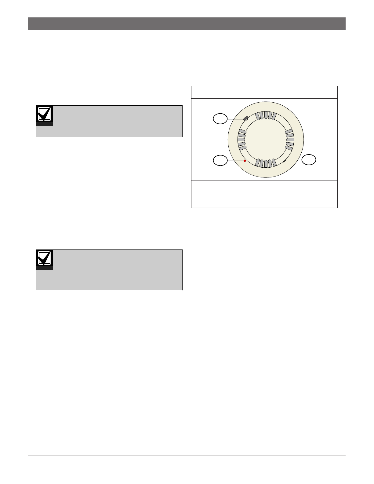
5. Install the two lithium batteries (Item 1 in Figure 2)
in the detector’s base and observe the polarity. These
batteries are supplied in a separate package.
Figure 2: Installing the Batteries
1
2.0 Mounting
The detector’s maximum wireless range in
open air is approximately 984 ft (300 m). In
normal residential or commercial
applications, keep the detector within 328 ft
(100 m) of the control panel receiver it is
assigned to. Temporarily mount the detector
using double-sided tape, and test it from the
desired location before permanently
mounting it.
1. Remove the detector’s dust cover. You can replace
the dust cover during construction periods, but
remove it when the alarm system is enabled.
2. The mounting plate has a base locking tab that, if
used, requires you to press the locking tab towards
the mounting surface to release the detector. If you
do not want the Lock-In feature, do not make
changes to the mounting plate. Use the Lock-In
feature by modifying the base locking tab as shown
in Figure 1.
1 - Lithium batteries (2)
2 - Programming serial number
6. A two-part sticker on the detector’s base (Item 2 in
Figure 2) contains the nine-digit programming serial
number. Remove one of the stickers and store it in a
safe place. You need the number to program the
detector from the control panel.
7. Connect the detector to the mounting plate and twist
it clockwise.
167770187
167770187
2
Bosch | 12/04 | 43177D2
RF280E Series | Installation Instructions | 4.0 Testing
3.0 Programming
Refer to your control panel wireless reference guide for
programming information.
4.0 Testing
4.1 Operational
Notify all concerned parties before and after
performing maintenance or testing the fire
alarm system.
1. When the system is free of alarms, check each
detector to ensure the red Alarm and Test LED
flashes approximately every 26 sec. This verifies the
detector is operating properly.
2. Test each detector to ensure it causes a control panel
alarm.
3. Alarm the detector by pressing and holding the Test
button for 9 to 12 sec.
The LED lights, the sounder sounds, and a Test
Report is sent to the control panel.
4. Release the Test button to end the test.
4.2 Sensitivity
The detector’s calibration is important in
determining its continued operation.
Depending on local regulations, the
frequency of calibration testing might be
required more often than once a year.
Test the detector’s sensitivity by pressing the Test button
and observing the Alarm and Test LED.
4.3 Manual Test
1. Press and hold the Test button (Item 1 in Figure 3).
2. Observe the Alarm and Test LED (Item 2 in
Figure 3). The detector can take up to 12 sec to enter
Test Mode.
Figure 3: Sensitivity Testing Components
1
2
1 - Test button
2 - Alarm and Test LED
3 - Cover latch
• If the detector is within the factory-marked
calibration range, it goes into alarm and the LED
steadily lights.
• If the detector is too sensitive, the LED rapidly
flashes four times (once every 0.5 sec) and the
detector goes into alarm with the LED steadily on.
• If the detector is not sensitive enough, the LED
slowly flashes twice (once every 2 sec) and the
detector goes into alarm with the LED steadily on.
• If the detector is not operational, it does not signal
an alarm. Return the unit for repair.
3
4.4 Visual Check
The RF280E Series includes the Chamber Check™
Automatic Trouble Indication. The detector uses this
feature to automatically indicate when its calibration is
out of the factory-listed range.
Check the detector’s sensitivity by visually inspecting it
and observing the Alarm and Test LED’s flash rate.
Normally, the flash rate is once every 26 sec. When the
detector is out of the sensitivity range, the LED quickly
flashes twice every 26 sec to indicate low sensitivity.
The LED quickly flashes twice every 15 sec for high
sensitivity, indicating a dirty chamber.
3Bosch | 12/04 | 43177D
 Loading...