

Bosch Rexroth VT-VRPD-2 Installation & Operation Manual
Installation and Operation
RE 30126-B/09.13
Replaces: 08.07
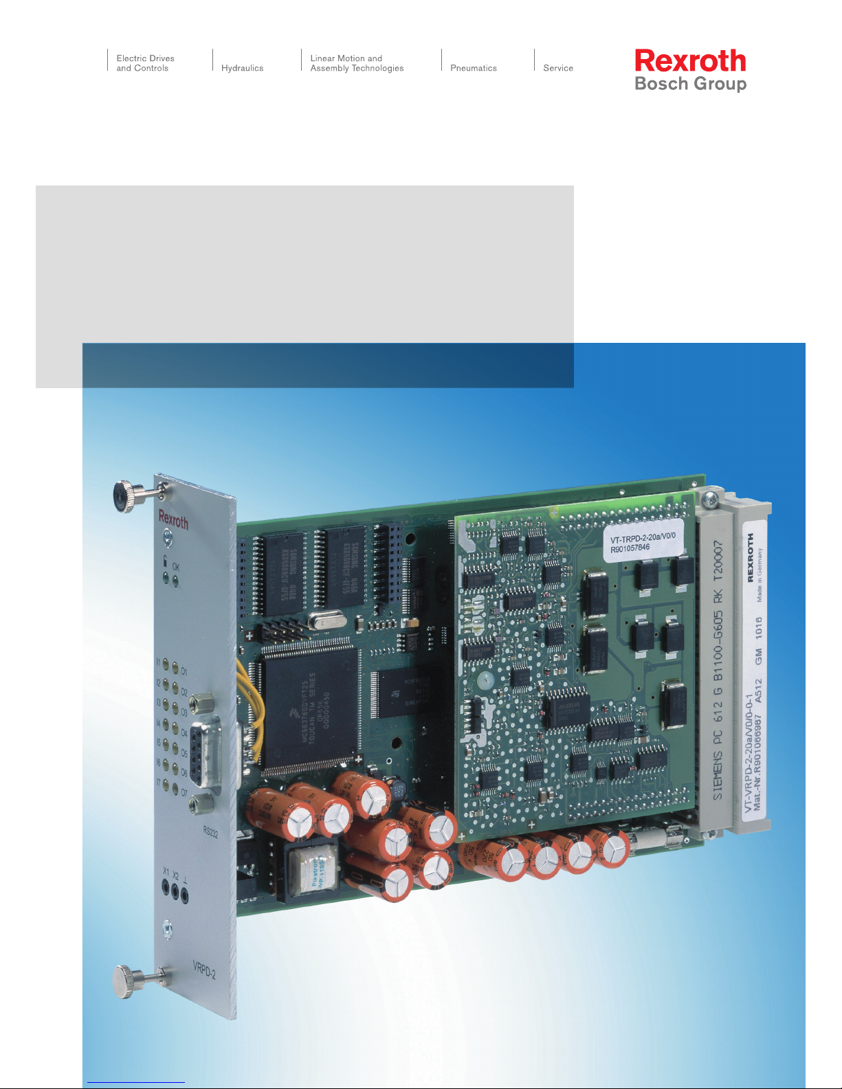
VT-VRPD-2 – Digital valve
amplifier for valve types
4WRE 6, component series 2X
4WRE 10, component series 2X

2/32 Bosch Rexroth AG | Hydraulics Installation and Operation | RE 30126-B/09.13

RE 30126-B/09.13 | Installation and Operation Hydraulics | Bosch Rexroth AG 3/32
Contents
1 General ...................................................................................................... 5
1.1 About this Manual ....................................................................................... 5
Additional Documentation ............................................................................................ 5
Characters and Symbols .............................................................................................. 6
1.2 Scope of Supply ......................................................................................... 7
1.3 Requirements ............................................................................................. 7
2 Installing the VRPD .................................................................................. 8
2.1 Safety Requirements .................................................................................. 8
Proper Use ................................................................................................................... 8
Personnel Selection and Qualifications ........................................................................ 9
Design Changes and Electrical Installation .................................................................. 9
2.2 Repair and Troubleshooting ..................................................................... 10
2.3 Transport, Storage and Handling the Controller Card ............................... 11
2.4 Card Installation ....................................................................................... 12
2.5 Edge Connector Terminals and Pin Assignments ..................................... 13
2.6 Installation Local Bus ................................................................................ 17
2.7 Connecting the proportional valve ............................................................ 18
2.8 Connecting the valve position transducer ................................................. 19
3 Startup of the VRPD Controller Card .................................................... 20
3.1 Preparing for Use ..................................................................................... 20
3.2 Installing BODAC software ....................................................................... 21
Installation Requirements ........................................................................................... 21
BODAC Setup ............................................................................................................ 21

4/32 Bosch Rexroth AG | Hydraulics Installation and Operation | RE 30126-B/09.13
3.3 Initial startup with BODAC ........................................................................ 22
4 VRPD Operation ..................................................................................... 23
4.1 Display/Input Keys and Connectors on the Front Panel ............................ 23
4.2 Diagnostics Test Jacks ............................................................................. 24
5 Diagnostics ............................................................................................. 25
5.1 Diagnostic Options on the VRPD Controller Card ..................................... 25
5.2 Diagnostics Using BODAC ....................................................................... 25
6 Detecting Errors ..................................................................................... 26
6.1 Error Messages ........................................................................................ 26
6.2 Changing fuses ........................................................................................ 27
7 Index ........................................................................................................ 29

RE 30126-B/09.13 | Installation and Operation Hydraulics | Bosch Rexroth AG 5/32
General 1
1 General
1.1 About this Manual
Before installing or operating your VRPD Controller card for the first time, you should
read this Manual. Please note the safety requirements described in section 2.1.
Persons involved with the start-up and operation of the controller card should have
proper training on the installation and operation of this type of equipment.
This manual is intended to inform you about the functions of this controller card and its
intended use.
The Manual contains important safety instructions on proper installation and operation
of the controller card. Observing these instructions will help you:
avoid hazards and dangers
minimize repair costs and downtime
increase the useful life and reliability of the controller card
Additionally, please observe all regulations that are in effect in the country and/or
community to prevent accidents and to protect the environment.
This manual only describes the installation and operation of the controller card. Information about starting up the controller card using BODAC software is located in a
separate document: “Operation of the BODAC Software and Starting up the VRPD
Control Card”. A list of documentation for the VRPD can be found in the “Additional
Documentation" section.
Additional Documentation
Additional information to this document “VRPD Digital Control for Electro-mechanical
and Electro-hydraulic Drives is available.
It contains:
RE sheet "RE 30 126" in paper form.
Document “ RE 30 126-B " Starting up the VRPD Control Card and Operation of
the BODAC Software ".
Internet:
http://www.boschrexroth.com/HACD
6/32 Bosch Rexroth AG | Hydraulics Installation and Operation | RE 30126-B/09.13
1 General
Characters and Symbols
The following characters and symbols are used in the manual:
¾ Action symbol: The text following this symbol describes actions. These should be
performed, from top to bottom, in the given order.
9 Result symbol: The text following this symbol describes the results of an action.
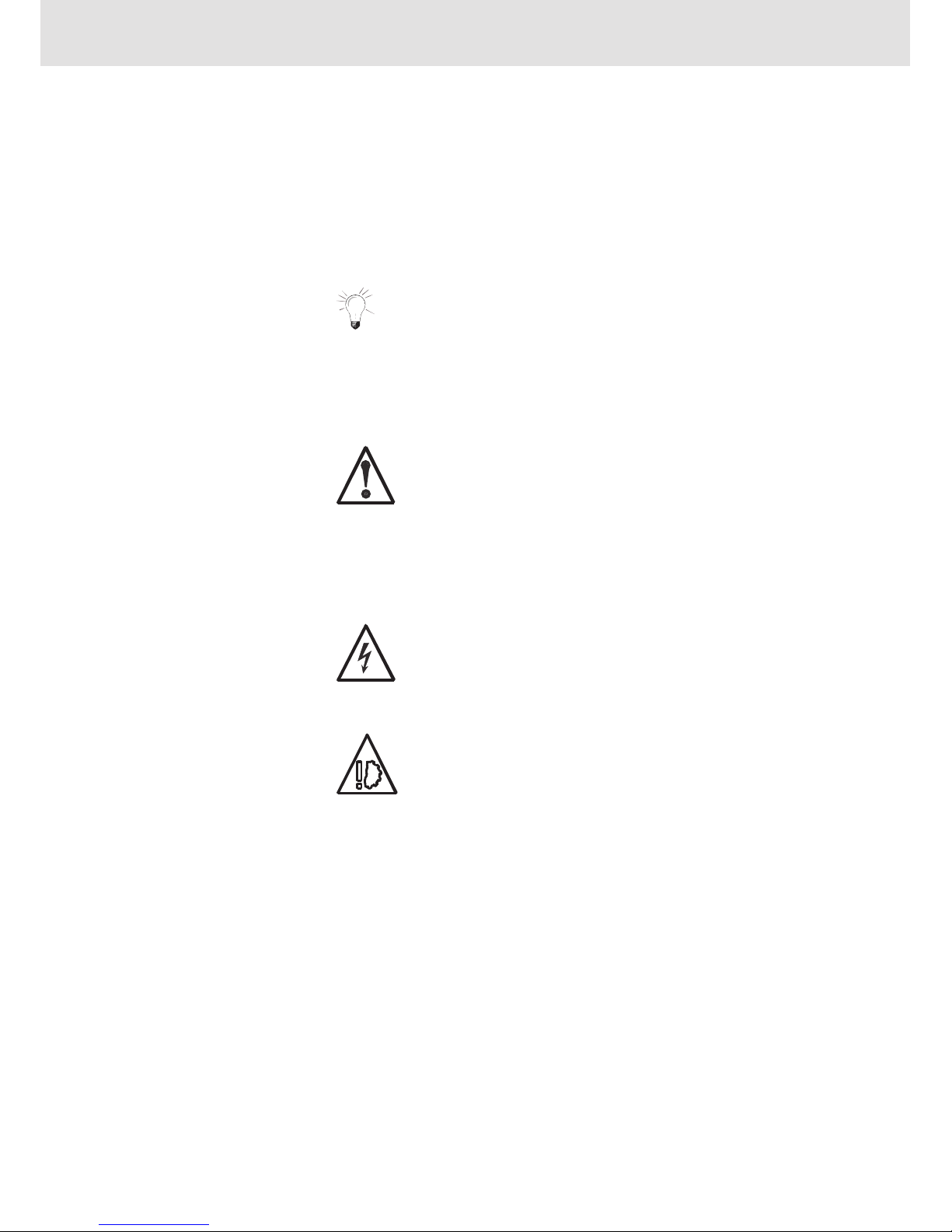
Following this symbol you will find notes and useful tips for optimal use
of the controller card..
Special safety notes are provided at the relevant locations. These are indicated by the
following symbols.
If the hazard source can be specifically indicated, the corresponding pictogram will be
used.
Electrical current hazard
This symbol refers to a hazardous condition caused by electrical current which, if not avoided, could result in death or serious injury.
Equipment damage
This symbol pertains to actions which could result in damage to
equipment.
Warning symbols
General hazard potential
Indicates a potentially hazardous condition which, if not avoided, could
result in death or serious injury

RE 30126-B/09.13 | Installation and Operation Hydraulics | Bosch Rexroth AG 7/32
General 1
1.2 Scope of Supply
The equipment is packed in anti-static packaging to protect the controller card from
electrostatic discharge. Observe instructions on the top side of the packaging.
Included in the shipment:
Controller Card VRPD
RE sheet RE 30 126-B
1.3 Requirements
Mounting the controller card in a card holder
VT 3002-2x/G64
described in datasheet RE 29 928.
The card holder should be used only inside a control cabinet, as there is no protection
from accidental contact.
If no power is provided by the user, the following power supply is available as an option:
VT-NE30
described in datasheet RE 29 929.

8/32 Bosch Rexroth AG | Hydraulics Installation and Operation | RE 30126-B/09.13
2 Installing the VRPD
2 Installing the VRPD
2.1 Safety Requirements
Operate the VRPD controller card only if it is not damaged and is in proper operating
condition and is applied for its intended purpose. Observe all safety and hazard instructions in the included documentation.
When faults occur, which compromise safety and result in changes in operating conditions, shut down the controller card immediately and notify responsible personnel.
Fault free and safe running of the controller card assumes appropriate transport, storage and installation, as well as proper startup and operation.
The VRPD Control Card has been built using the latest technology, and in accordance
with recognized safety standards. Nevertheless, operation may result in hazard to
persons or property if:
The VRPD Controller Card is not used properly.
The VRPD Control Card is not installed, commissioned and operated by qualified
persons.
Changes or modifications are made to the VRPD controller card.
Safety requirements and safety notes are not observed.
The VRPD controller card is intended for industrial use.
The card must not be operated until it has been determined that the system in which
the controller card is installed, meets all applicable standards and safety regulations
for the application.
In European countries: EC Directive 89/392/EWG (Machine Directive)
Operation is permitted only when applicable EMC regulations for the application are
met.
Adherence to limits defined by regulations and standards are the responsibility of the
manufacturer of the system or machine.
In European countries: EC Directive 89/336/EWG (EMC Directive)
In the United States: National Electrical Code (NEC) and National Electrical Manufacturers Association (NEMA), as well as local standards should be observed. The operator is required to adhere to the above named standards at all times.
Proper Use
The VRPD is designed to control Electromechanical and Electrohydraulic Drives.
Possible application area’s are:
Valve Amplifiers
Proper use requires adherence to the manuals and supplementary documentation,
and observing relevant safety and operating standards.

RE 30126-B/09.13 | Installation and Operation Hydraulics | Bosch Rexroth AG 9/32
Installing the VRPD 2
Personnel Selection and Qualifications
Operation and startup of the VRPD controller card requires specialized skills. Therefore this work should be performed only by properly trained individuals.
Only persons who are trained or properly instructed should start up and operate the
VRPD controller card. Additionally the oversight of a qualified supervisor may be advised.
Personnel are considered qualified if they are familiar with the installation, startup and
operation of the VRPD controller card, and with all the warning notes and safety regulations contained in the accompanying documentation.
Work on the electrical equipment must be performed only by qualified specialists or by personnel appropriately instructed and under the supervision and
guidance of persons qualified and familiar with electrical safety standards.
An electrical specialist is someone who, based on his technical knowledge and training, as well as knowledge of the relevant standards, is able to evaluate the tasks assigned to him, recognize potential hazards and take the appropriate safety measures.
Repair and troubleshooting requires specialized skills. Therefore, this work should be
performed only by trained and designated specialists.
Design Changes and Electrical Installation
User changes to the VRPD controller card may result in safety hazards.
Note the following recommendations on electrical installation:
Use low-capacitance cables. Make cable connections without intermediate con-
nections whenever possible.
Control electronics should be isolated from electromagnetic noise sources (IE:
V/F drives).
Power wiring should not be routed in the vicinity of control electronics.
Power wiring should not be routed in the vicinity of control wiring or cables.
Route sensor lines separately.
Maintain a distance of at least 1 meter from antenna lines, RF devices and radio
equipment.
When using differential inputs switch both inputs on and off at the same time.
When switching signal inputs, use dry circuit rated relays with gold-plated con-
tacts (low voltages, low currents)
Always shield all analog signal lines. Connect shields at the card end only, con-
necting to the "Shield" terminal, and leave the other end open to prevent ground
loops.
Connect to an appropriate system ground using stranded copper wire (min
2.5mm
2
/ 12 AWG)
The system ground is an essential component of the EMC protection for the con-
troller card. The ground provides a path for noise that could otherwise enter the
controller card through the signal and power supply lines. Noise is bypassed only
if the sys-tem ground does not couple noise into the controller card.
Operation and Startup
Repair and troubleshooting

10/32 Bosch Rexroth AG | Hydraulics Installation and Operation | RE 30126-B/09.13
2 Installing the VRPD
Bosch Rexroth also recommends shielding solenoid wiring.
Do not use logical signals from the controller card (IE: “OK” signal) for switching
machine safety circuits
(see European Norm "Safety Requirements for Fluid Power Systems and Components" EN982:1996).
2.2 Repair and Troubleshooting
If the control cabinet contains additional electrical components utilizing high voltage,
always observe safety standards to prevent accidents! Use appropriate protective
gear, such as safety shoes and safety gloves, when prudent!
Use appropriate tools (IE: insulated tools)
Before opening control cabinet doors, open the main disconnect.
To ensure safe working conditions, observe the following safety rules:
Remove all power
Ensure against unintended energization: lockout devices when possible, and use
lockout warning tags
Verify that voltage is not present
Cover or close off adjacent areas that are still energized.
If work on energized components is necessary, have a second per-son present as a
safety backup to actuate an E-STOP switch or open the main disconnect, if necessary. Use insulated tools only.
 Loading...