

Bosch Rexroth VT-HNC100 3X/S Technical Data Manual
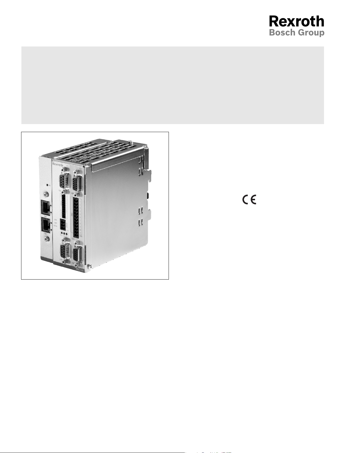
Digital drive controller
for hydraulic axes
withsercos interface
Type VT-HNC100.../S
RE 30159
Edition: 2012-03
Replaces: 09.11
Component series 3X
H7644
Contents
Features 2
Ordering code 3
Software project planning 4
Overview of the controller functions 4
System overview 5
System overview, interfaces 6
Technical data 7
Pin assignment 12
Unit dimensions 13
Project planning / maintenance instructions /
additional information 14
RE 30159, edition: 2012-03, Bosch Rexroth AG

2/14 VT-HNC100.../S | Digital drive controller
Features
The VT-HNC100...3X/S digital drive controller complies
with the specific requirements for closed-loop control
of hydraulic linear drives.
It is designed for being used in rough industrial environments as regards interference immunity, mechanical
vibration, shock, and climate resistance.
Areas of application
Machine tools
Bending machines
Technology functions
Positioning
Velocity controller:
– Controlled
– Regulated
Force controller
Substitutional closed-loop control
Moving without following error
Quadrant error correction
Hydraulic axes
Measurement system:
– Incremental TTL 5V
– SSI transducer
– EnDat 2.2
– Analog 0 to ±10 V
Actuating variable output voltage or current
Freely confi gurable controller variants
– Position / force / velocity controller
– Substitutional closed-loop control (position/force)
Programming
Via the control with IndraWorks
Operation
IndraWorks
Process connection
Digital inputs and outputs,
Analog inputs and outputs,
sercos II or sercos III to communicate with a supe-
rior control system
Assembly
Top hat rail 35 mm
CE conformity
CE conformity according to EMC Directive 2004/108/EC
and EMVG (Act on electromagnetic compatibility of
operating media) from February 26, 2008
Harmonized standards used:
EN 61000-6-2:2005
EN 61000-6-3:2007
More information
www.boschrexroth.com/hnc100
Bosch Rexroth AG, RE 30159, edition: 2012-03
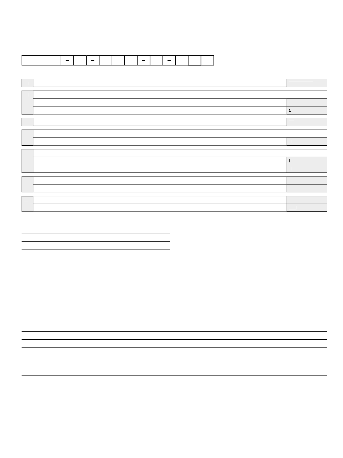
Ordering code
01
Serial unit
V
00
02
s
C
Standard
03
)
3X
04Bus connectio
/
)
S
05Position transducer
)
)
)
)
)
n
thout
00
/
/
VT-HNC1
Digital drive controller | VT-HNC100.../S 3/14
7
Versions for an hydraulic axi
Compact
Component series 30 to 39 (30 to 39: Unchanged technical data and pin assignment
n
sercos II
Incremental/EnDat 2.2/SSI (standard)
EnDat 2.2/SSIonly in connection with Compact version
sercos II (only in connection with Compact version
sercos III (only in connection with Standard version
Optio
Wi
Available variants
Type Material number
VT-HNC100-C-3X/S-S-00/000 R901112919
VT-HNC100-1-3X/S-I-30/000 R901234133
sercos III
1
2
2
1)
Ethernet service interface only in connection with sercosIII
2)
Can be selected by means of the IndraWorks PC program
T-HNC1
Included in the scope of delivery:
Mating connector for
X1S (type Phoenix Mini Combicon 3-pole),
X2D (type Phoenix Micro Combicon 8-pole and/or Phoenix Mini Combicon 12-pole),
X2A (type Phoenix Micro Combicon 8-pole and/or HD-SUB 15-pole),
X8M (type Phoenix Micro Combicon 8-pole and/or HD-SUB 15-pole)
Recommended accessories (can be ordered separately)
Denomination Material number
Interface cable RS232, length 3 m R900776897
USB RS232 converter R901066684
Cable set VT17220-1X/HNC100-3X, length 2 m,
for analog signals (connection X2A) or digital position measurement systems (connection X8M) with
HDconnector and open breakout cable for VT-HNC100-1-3X
Cable set VT17220-1X/HNC100-3X length 2 m,
for analog signals (connection X2A) or digital position measurement systems (connection X8M) with
FK-MC connector and open breakout cable for VT-HNC100-C-3X
R901189300
R901189302
RE 30159, edition: 2012-03, Bosch Rexroth AG

4/14 VT-HNC100.../S | Digital drive controller
Software project planning
Project planning
Developing application-specific data sets forms the basis
for the function of the VT-HNC100...3X/S. These data sets
are generated on the PC and sent to the VT-HNC100...3X/S
using a serial Ethernet interface. This software parameterization is implemented according to fix steps:
1. Depending on the assignment, the inputs and outputs
and the parameters used are defined.
2. The parameters (selection of transducers and controllers) are defined.
3. The data are sent to the VT-HNC100...3X/S.
4. The settings are optimized at the machine.
PC program "IndraWorks"
To implement the project planning tasks, the "IndraWorks"
PC program is available to the user. It serves for parameterizing, setting, and diagnosing the VT-HNC100...3X/S.
Scope of service:
Comfortable dialog functions for setting the parameters
online or offl ine
Dialog window for the online setting of the param-
etervalues
Various options for the display of the process variables
Notice:
The PC program "IndraWorks" is not covered by the scope
of delivery.
Queries: support.nc-systems@boschrexroth.de
Overview of the controller functions
Position controller:
PDT1 controller
Linear amplifi cation characteristic curve
Direction-dependant gain adjustment
Adaptation of the valve characteristic curve
Valve characteristic diagram
Fine positioning
Residual voltage principle
Compensation of zero point errors
State feedback via:
– Force,
– Position
Command value feedforward
Force controller:
PIDT1 controller
I share switchable via window
Diff erential pressure evaluation
Additive velocity addition
Velocity controller:
PI controller
I share switchable via window
Monitoring functions:
Dynamic following error monitoring
Traversing range limits (electronic end switches)
Cable break monitoring for position transducers
Cable break monitoring for sensors with out-
put4to20mA
Bosch Rexroth AG, RE 30159, edition: 2012-03
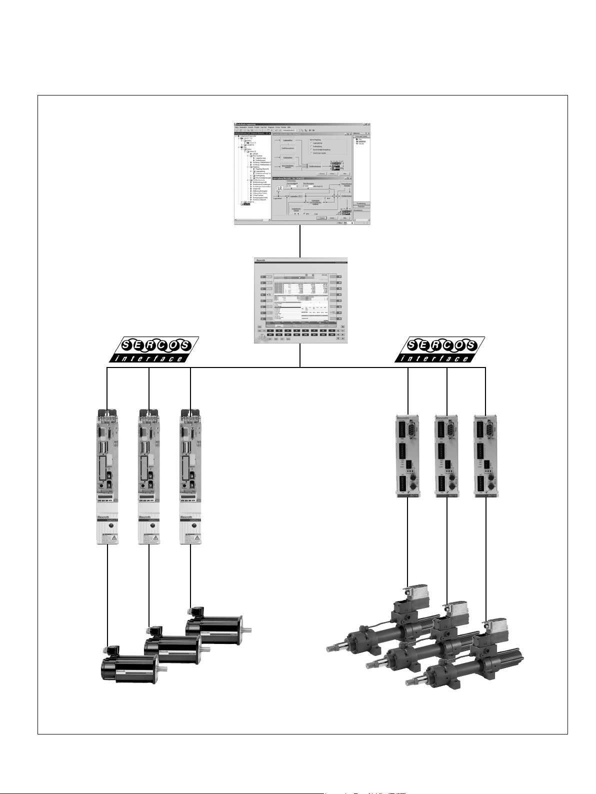
System overview
Example
(engineering environment)
Digital drive controller | VT-HNC100.../S 5/14
IndraWorks
IndraMotion MTX
(CNC control)
IndraDrive HNC100-C-3X/S
Hydraulic axesElectrical axes
RE 30159, edition: 2012-03, Bosch Rexroth AG
 Loading...