

Bosch Rexroth Sytronix FcP 5020 Quick Start Manual
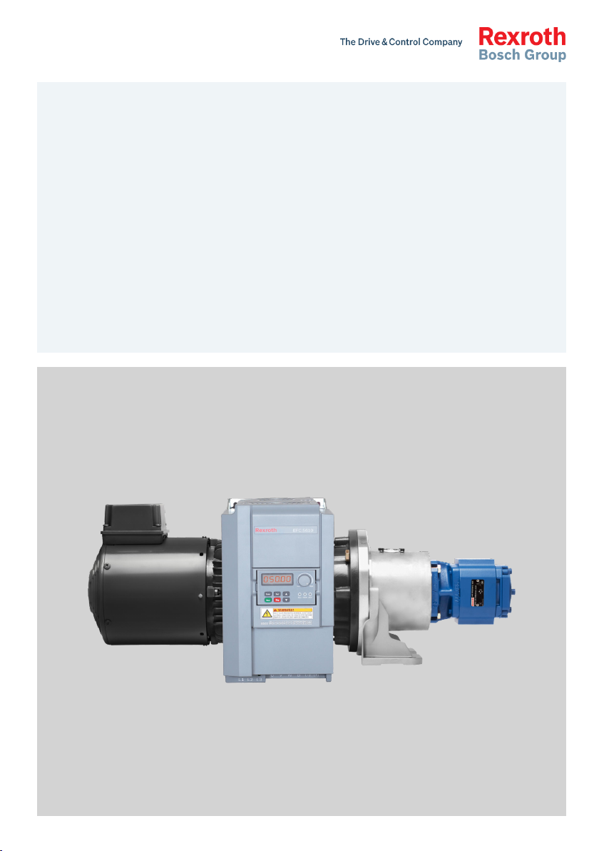
Sytronix
FcP 5020
Frequency-Controlled Pump Drive System
Quick Start Guide
R912006684
Edition 02
Bosch Rexroth AG FcP 5020
WARNING
Record of Revision
Edition Release Date Notes
DOK-RCON03-FcP5020*Eco-QU01-EN-P 2016.03 Preliminary
DOK-RCON03-FCP5020****-QU02-EN-P 2016.09 New functions
Version Matching Table
Frequency converter EFC 5610 firmware version ASF version
03V12
03V14
01V04 or 01V06
03V18 and above 01V08
Introduction of this Documentation
This Quick Start Guide is derived from the Operating Instructions which includes the product data in details.
Personal injury and property damage caused by
incorrect application, installation or operation!
Never work with or control the product before reading through
● Safety Instructions which delivered with EFC 5610
● Safety descriptions in the Operating Instructions
Reference
For documentation available in other type or language, please consult your local
sales partner or check www.boschrexroth.com.
Copyright
© Bosch Rexroth (Xi'an) Electric Drives and Controls Co., Ltd. 2016
This document, as well as the data, specifications and other information set
forth in it, are the exclusive property of Bosch Rexroth (Xi'an) Electric Drives
and Controls Co., Ltd. It may not be reproduced or given to third parties without
its consent.
Liability
The specified data is intended for product description purposes only and shall
not be deemed to be a guaranteed characteristic unless expressly stipulated in
the contract. All rights are reserved with respect to the content of this documentation and the availability of the product.
RS-95773a12ad36be1c0a347ea500f43669-2-en-US-20

FcP 5020 Bosch Rexroth AG
Table of Contents
Table of Contents
Page
1 Type Code.............................................................................................. 1
1.1 Frequency Converter Type Code Description........................................ 1
1.2 FcP 5020 ASF Type Code Description................................................... 2
2 Scope of Supply..................................................................................... 4
3 Documentation Reference .................................................................... 4
4 Function Specification........................................................................... 5
5 Initial Start Up....................................................................................... 7
6 Electric Connection............................................................................. 10
6.1 Overview.............................................................................................. 10
6.2 Analog Input......................................................................................... 11
6.3 Analog Output...................................................................................... 13
6.4 Motor Temperature Thermal Protection............................................... 14
6.5 Digital Input......................................................................................... 15
6.6 Digital and Relay Output...................................................................... 16
7 Block Diagram of Main Functions........................................................ 17
7.1 Overview.............................................................................................. 17
7.2 Flow Command Processing.................................................................. 17
7.3 Pressure Command Processing........................................................... 19
7.4 Pressure Feedback Input..................................................................... 21
7.5 Quick Configuration For Rexroth HM20 Pressure Sensor.................... 22
7.6 Quick Configuration For Rexroth MOT-FC_HOY Motor ........................ 24
7.7 p/Q PID Control................................................................................... 26
7.8 Restore ASF Parameter........................................................................ 30
7.9 Extension Functions............................................................................. 31
7.9.1 Master / Slave Function....................................................................... 31
7.9.2 Sleep / Wake Function......................................................................... 33
7.9.3 Two Points / Double Pump Control..................................................... 35
7.9.4 Pressure Drop / Overshoot Compensation.......................................... 37
7.9.5 Pump Power Limitation....................................................................... 39
7.9.6 Hydraulic Soft Start and Separate Acceleration Ramp........................ 40
7.10 Protection Function............................................................................. 41
DOK-RCON03-FCP5020****-QU02-EN-P
I

Bosch Rexroth AG
FcP 5020
Table of Contents
Page
7.10.1 Overview.............................................................................................. 41
7.10.2 Pressure Sensor Failure Detection....................................................... 41
7.10.3 Actual Pressure Monitoring.................................................................. 45
7.10.4 Oil Change Warning / Error Function................................................... 46
7.10.5 Pressure and Flow Command Limit..................................................... 47
7.10.6 Pump Thermal Protection.................................................................... 48
7.10.7 Sensor Monitoring............................................................................... 49
7.11 CytroPac Configuration....................................................................... 51
7.11.1 Overview.............................................................................................. 51
7.11.2 Load CytroPac Configuration............................................................... 51
7.11.3 CytroPac Sensor Monitoring ............................................................... 51
7.11.4 LED Flash Showing Converter Status.................................................. 52
8 FcP 5020 Parameter List...................................................................... 53
8.1 Terminology and Abbreviation in Parameter List................................. 53
8.2 Group F1: Quick Start Parameter........................................................ 54
8.3 Group F2: Input and Output Parameter............................................... 56
8.4 Group F3: p/Q PID Parameter.............................................................. 59
8.5 Group F4: System Protection and Pump Function Parameter............. 60
8.6 Auto-modified EFC Parameters in FcP Initialization............................ 62
8.7 Changed Setting Parameter by Load CytroPac Configuration............. 63
8.8 Monitoring Parameter.......................................................................... 65
9 Fieldbus Communication..................................................................... 66
9.1 Brief Introduction................................................................................ 66
9.2 Frequency Converter Parameter Address............................................ 66
10 Diagnosis............................................................................................. 69
10.1 Warning Code...................................................................................... 69
10.2 Error Code........................................................................................... 70
Index.................................................................................................... 71
II
DOK-RCON03-FCP5020****-QU02-EN-P
FcP 5020
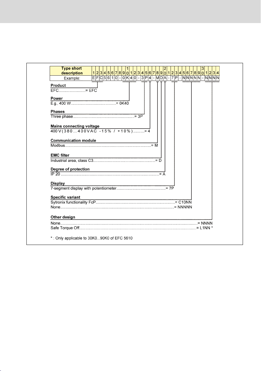
1 Type Code
1.1 Frequency Converter Type Code Description
Bosch Rexroth AG
Type Code
Fig. 1-1: EFC 5610 type code
This type code can be found on the Rexroth EFC converter.
DOK-RCON03-FCP5020****-QU02-EN-P
1/75
Bosch Rexroth AG
Type Code
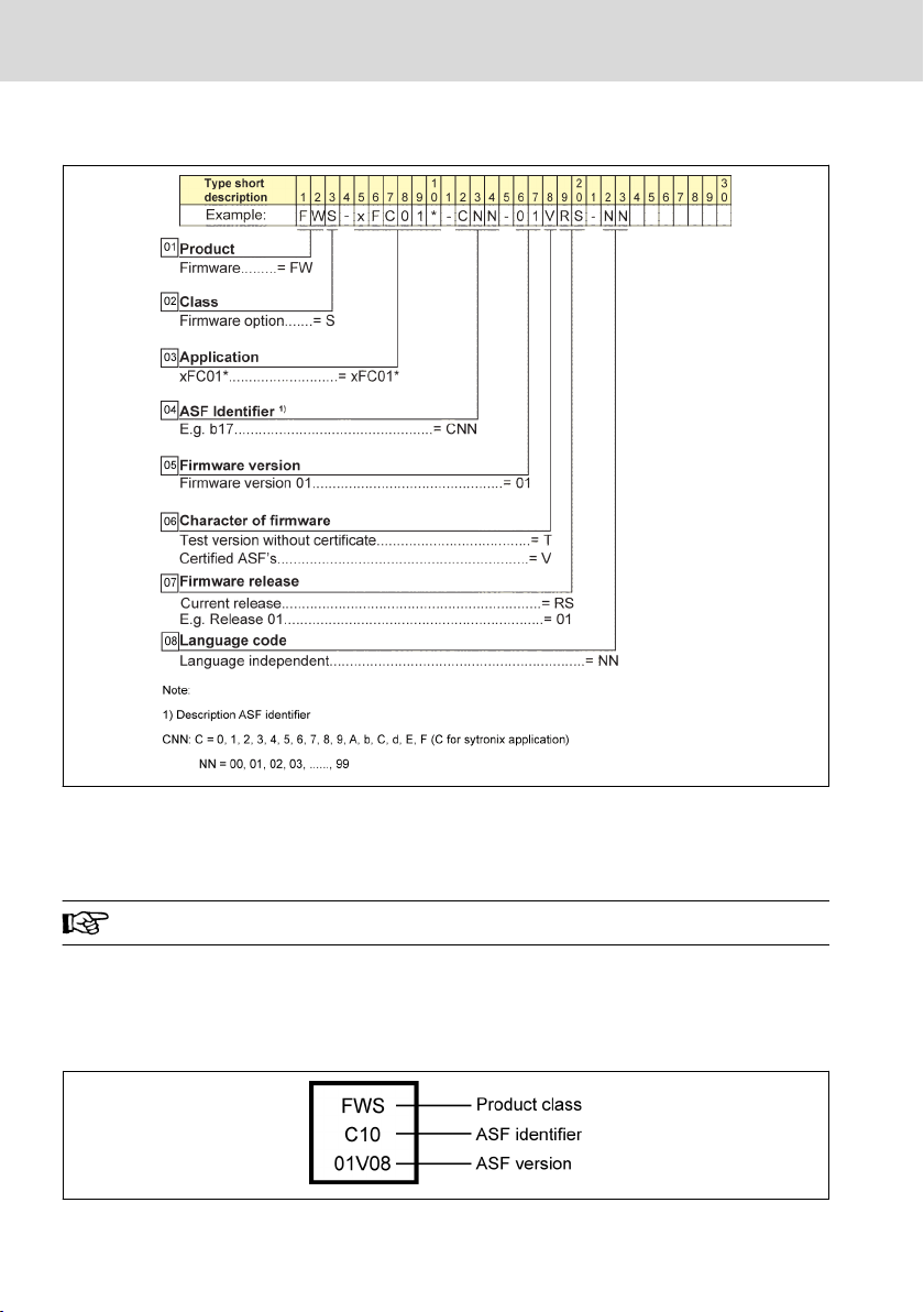
1.2 FcP 5020 ASF Type Code Description
FcP 5020
Fig. 1-2: FcP 5020 ASF type code
FcP 5020 ASF software material number: R912006662
FcP 5020 ASF software type code: FWS-XFC01*-C10-01VRS-NN
ASF: Application Specific Firmware.
The ASF type code will not be printed and placed on the EFC converter, but only
a square adhesive label on the side, which represents important information
from ASF type code:
For example:
Fig. 1-3:
2/75
ASF version information
DOK-RCON03-FCP5020****-QU02-EN-P

FcP 5020 Bosch Rexroth AG
Type Code
Parameter Name Value
F0.01 ASF version *
F0.02 ASF identifier 0x0C10
F0.03 ASF API required version *
F0.06 ASF evaluation time *
F0.07 ASF API version *
Bit0: ASF valid
Bit1: API compatible
Bit2: ASF certified
Bit3…Bit7: Reserved
Bit8: ASF evaluation period expired
F0.10 ASF status
Bit9: ASF invalid
Bit10: ASF API incompatible
Bit11: Reserved
Bit12: ASF runtime exceeded
Bit13: ASF stack overflow
Bit14…Bit15: Reserved
Tab. 1-1: FcP 5020 ASF basic information
* For accurate information, refer to the actual data provided on the product.
DOK-RCON03-FCP5020****-QU02-EN-P
3/75

Bosch Rexroth AG
FcP 5020
Documentation Reference
2 Scope of Supply
If any item is found missing from standard supply package as listed below,
please contact Bosch Rexroth's local sales partner at your earliest convenience.
● Frequency Converter EFC 5610 with integrated Sytronix software
● Safety Instructions (available in multiple languages)
● EFC 5610 Quick Start Guide
● FcP 5020 ASF Quick Start Guide
3 Documentation Reference
Following documentations about the components could be found on Bosch
Rexroth homepage:
www.boschrexroth.com -> Products -> Electric Drives and Controls -> Product
Catalog -> CAD and documentation
Title
Rexroth Frequency Converter EFC 3610 /
EFC 5610 Series
Rexroth Frequency Converter EFC 3610 /
EFC 5610 Series
Pressure transducer with integrated electronics-type HM20
Rexroth IndraDyn E Standard Motors MOTFC for Frequency Converter Operation
Tab. 3-1: Documentation reference
Document
number
Document
type
Catalog
R912005856 Quick Start Guide
Controller / Converter
R912005854
Operating Instructions
30272 Data sheet Presssure Sensor
R911343624
Project Planning
Manual
Motor
4/75
DOK-RCON03-FCP5020****-QU02-EN-P
FcP 5020
Bosch Rexroth AG
Function Specification
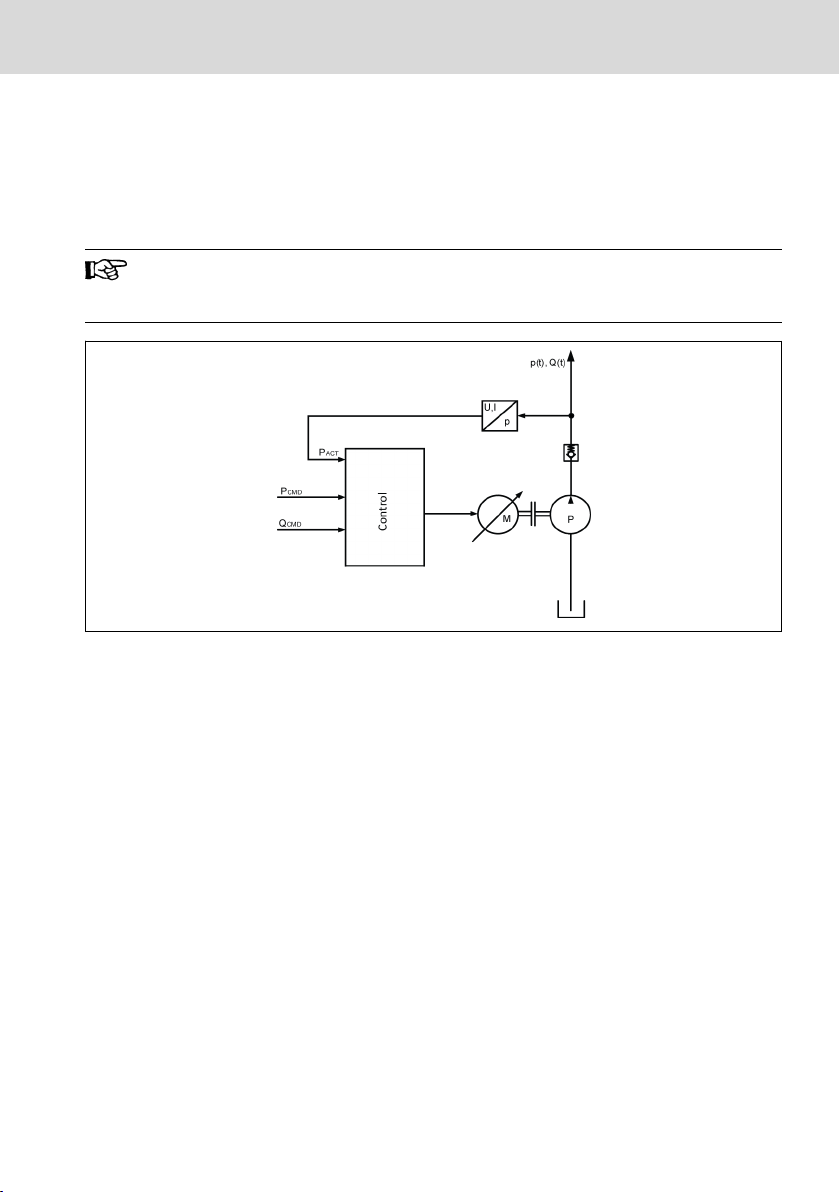
4 Function Specification
FcP 5020 ASF is developed based on the EFC 5610 hardware platform to be
used for pressure and flow control. FcP 5020 has the functionality to automatic
switch between pressure and flow mode. The typical application is shown as below.
This document only covers FcP 5020 relating functionalities. Please
review documentations in chapter 2 "Scope of Supply" on page 4
prior to applying power to EFC drive.
Control: Drive control
P
: Pressure actual value
ACT
Fig. 4-1: The diagram of typical application
P
: Pressure command
CMD
Q
: Flow command
CMD
FcP 5020 receives the pressure command generated by an external controller,
i.e. PLC or CNC, and the pressure feedback generated by the actual pressure
sensor mounted in the hydraulic system. By using both of the pressure command and the pressure feedback, the frequency converter is able to control the
motor speed automatically and in turn regulate the output flow of hydraulic
pump. The same mechanism is applicable to flow-based control mode to achieve
the same regulation purpose on the output flow of hydraulic pump.
The product provides the following features.
● Pressure / flow setting
– Easy command setting (internal commands, and 4 switchable parameters
for pressure command)
– Command setting possibility via analog or communication*
– Unique digital filtering for pressure command rising and dropping
– Preset standby mode (with minimum flow and pressure)
* External hardware for communication is required.
DOK-RCON03-FCP5020****-QU02-EN-P
5/75

Bosch Rexroth AG
FcP 5020
Function Specification
* Supported communication protocols: Profibus, CANopen, SercosIII, MultiEthernet, Modbus.
● Pressure signal feedback
– Compatible with different types of pressure sensors (unlimited scaling for
the analog input signal)
– High resistance capability to electromagnetic interference (with the use of
high precision digital filter device for signal filtering)
– Quick configuration for Rexroth HM20 pressure sensor
● Quick configuration for Rexroth MOT-FC_HOY motor
● p/Q PID control
– p/Q control with automatic switching between pressure and flow control
modes
– Flow control
– Pressure control
– With 2 groups of switchable parameters provided
● Restore ASF parameter
● Extension functions
– Master / slave control
– Sleep / wake function
– Two points / double pump control
– Pressure drop / overshoot compensation
– Pump power limitation
– Hydraulic soft start and separate acceleration ramp
● Protection function
– Pressure sensor failure detection
– Actual pressure monitoring
– Oil change warning / error
– Pressure and flow command limit
– Pump thermal protection
– Sensor monitoring
● CytroPac configuration*
– Load CytroPac configuration
– CytroPac sensor monitoring
– LED flash showing converter status
* CytroPac is a specified compact Sytronix system with sensors. It applies
FcP 5020 application software.
6/75
DOK-RCON03-FCP5020****-QU02-EN-P

FcP 5020 Bosch Rexroth AG
Initial Start Up
5 Initial Start Up
After the electric hydraulic system has been correctly assembled, users can take
following steps for initial start up.
1. Select pressure sensor via F2.10 (for option ''0: Others", please set F2.06,
F2.07 manually).
2. Choose motor parameter via F1.15 and F1.16 for Rexroth MOT-FC_HOY motor. For other motors set F1.15 to 0, and set motor parameter in EFC parameter group C, please reference EFC 5610 quick start guide (material
number is R912005856).
3. Set pressure command via F1.03...F1.08 and flow command via F1.11,
F1.12.
4. Run the FcP system.
● The pressure command F1.05 and flow command F.12 default val-
ues are set to low values to prevent potential machine damage
caused by improper use during initial start up.
● For CytroPac application, set F1.20 according to different Cytro-
Pac type.
Code Name Setting range Default Min. Attri.
0: Depend on the value of
F1.04
F1.03 Pressure command source
F1.04 Pressure command selection
Pressure command digital set-
F1.05
ting 0
Pressure command digital set-
F1.06
ting 1
Pressure command digital set-
F1.07
ting 2
1: Select by digital input (F1.04
shows status)
0 - Stop
2: Analog input
3: Communication
0: Pressure command digital
setting 0
1: Pressure command digital
setting 1
2: Pressure command digital
0 - Run
setting 2
3: Pressure command digital
setting 3
0.0...1,000.0 bar 10.0 0.1 Run
0.0...1,000.0 bar 10.0 0.1 Run
0.0...1,000.0 bar 10.0 0.1 Run
DOK-RCON03-FCP5020****-QU02-EN-P
7/75

Bosch Rexroth AG
FcP 5020
Initial Start Up
Code Name Setting range Default Min. Attri.
Pressure command digital set-
F1.08
ting 3
0.0...1,000.0 bar 10.0 0.1 Run
0: Depend on the value of
F1.12
F1.11 Flow command source
1: Analog input (positive / nega-
0 - Stop
tive)
2: Communication
F1.12 Flow command digital setting 0...5,000 rpm 400 1 Run
F1.15 Motor type
0: Others
1: MOT-FC_HOY
1 - Stop
0: No selection
1...5: Reserved
6: 1.5 kW
7: 2.2 kW
8: 3 kW
9: 4 kW
10: 5.5 kW
11: 7.5 kW
F1.16 Motor power level
12: 11 kW
13: 15 kW
0 - Stop
14: 18.5 kW
15: 22 kW
16: 30 kW
17: 37 kW
18: 45kW
19: 55 kW
20: 75 kW
21: 90 kW
0: No selection
CytroPac parameter initializa-
F1.20
tion
1: CytroPac Basic
2: CytroPac Advanced
0 - Stop
3: CytroPac Advanced + Comm.
Pressure feedback correspond-
F2.06
ing to 10V or 20mA
0.1...1,000.0 bar 100.0 0.1 Stop
8/75
DOK-RCON03-FCP5020****-QU02-EN-P

FcP 5020
Bosch Rexroth AG
Initial Start Up
Code Name Setting range Default Min. Attri.
Pressure feedback null offset in
F2.07
V or mA
0.0...5.0 V, mA
4.0
(mA)
0.1 Stop
0: Others
1: HM20-2X/10-C
2: HM20-2X/50-C
3: HM20-2X/100-C
4: HM20-2X/160-C
5: HM20-2X/250-C
6: HM20-2X/315-C
7: HM20-2X/400-C
8: HM20-2X/630-C
F2.10 Pressure sensor type
9: Reserved
3 - Stop
10: Reserved
11: HM20-2X/10-H
12: HM20-2X/50-H
13: HM20-2X/100-H
14: HM20-2X/160-H
15: HM20-2X/250-H
16: HM20-2X/315-H
17: HM20-2X/400-H
18: HM20-2X/630-H
Tab. 5-1: Parameter list of initial start up
DOK-RCON03-FCP5020****-QU02-EN-P
9/75
Bosch Rexroth AG
Electric Connection
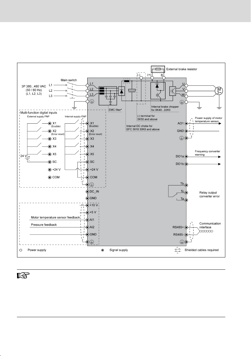
6 Electric Connection
6.1 Overview
FcP 5020
Fig. 6-1: Wiring Diagram
FcP 5020 I/O functionality is given higher priority over the stand-
●
ard EFC functions. The standard EFC functionality assigned to terminal will be ignored and taken over by the ASF terminal assignment (non-zero entries in ASF).
● For details about the wiring of temperature sensor as shown in
the diagram above, please refer to EFC 5610 operating instructions (material number is R912005854).
10/75
DOK-RCON03-FCP5020****-QU02-EN-P
FcP 5020 Bosch Rexroth AG
Electric Connection
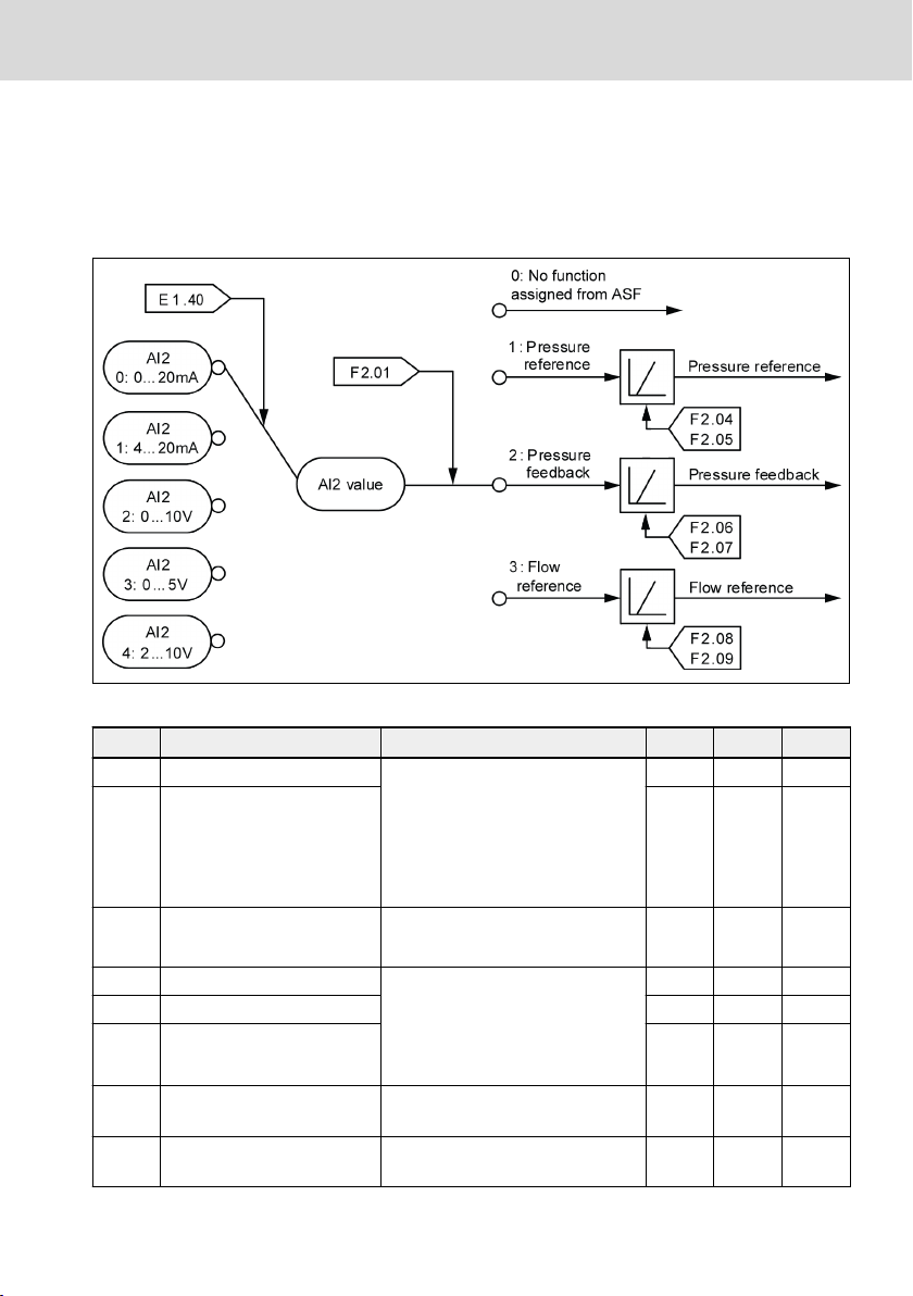
6.2 Analog Input
This section shows how analog input can be configured. The following figure is
an example for analog input AI2, which has been assigned to pressure feedback.
The configuration for AI1 and EAI is similar to AI2, only with different parameters
shown in the table below.
Fig. 6-2:
Example with analog input AI2 assigned to pressure feedback
Code Name Setting Range Default Min. Attri.
E1.35 AI1 input mode 0: 0...20 mA
2 - Run
1: 4...20 mA
E1.40 AI2 input mode 1 - Run
2: 0...10 V
3: 0...5 V
4: 2...10 V
H8.05 EAI input mode
F2.00 Analog input AI1 0: No function assigned from ASF
F2.01 Analog input AI2 2 - Stop
External analog input EAI
F2.02
(-10V...10V, 4...20mA)
Pressure command corre-
F2.04
sponding to 10V or 20mA
Pressure command null off-
F2.05
set in V or mA
DOK-RCON03-FCP5020****-QU02-EN-P
0...4 (same as E1.35)
5: -10V...10V
0 - Stop
0 - Stop
1: Pressure command
2: Pressure feedback
3: Flow command
0 - Stop
0.1...1,000.0 bar 10.0 0.1 Stop
0.0...5.0 V, mA 0.0 0.1 Stop
11/75

Bosch Rexroth AG
FcP 5020
Electric Connection
Code Name Setting Range Default Min. Attri.
Pressure feedback corre-
F2.06
sponding to 10V or 20mA
Pressure feedback null off-
F2.07
set in V or mA
Flow command correspond-
F2.08
ing to 10V or 20mA
Flow command null offset in
F2.09
V or mA
Tab. 6-1: Analog input parameter list
0.1...1,000.0 bar 100.0 0.1 Stop
0.0...5.0 V, mA
4.0
(mA)
0.1 Stop
1...5,000 rpm 400 1 Stop
0.0...5.0 V, mA 0.0 0.1 Stop
As the default FcP 5020 configuration, analog input AI2 [F2.01 = 2] is configured
as the pressure feedback input. Analog input AI1 or EAI1 has no preassigned
configuration by the FcP 5020.
For broken wire protection of analog input, please check the following table for
setting range of E1.61. For more information please refer to EFC 5610 converter
document (R912005856 or R912005854).
Code Name Setting Range Default Min. Attri.
0: Inactive
E1.61 Broken wire protection
1: Warning
0 - Stop
2: Error
Tab. 6-2: Parameter E1.61 for broken wire protection
Wire broken monitoring function for all analog inputs can be activated by E1.61. Default value of E1.61 has been set to 0 in FcP 5020
and 2 in CytroPac default setting.
12/75
DOK-RCON03-FCP5020****-QU02-EN-P
FcP 5020 Bosch Rexroth AG
Electric Connection
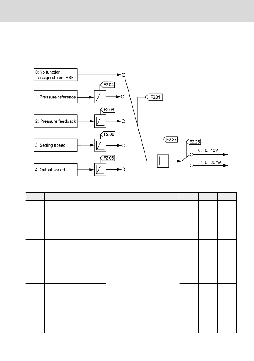
6.3 Analog Output
This section shows how analog output can be configured. The following figure is
an example for analog input AO1. The configuration for EAO is similar to AO1,
only with different parameters shown in the table below.
Fig. 6-3: Example with analog output AO1
Code Name Setting Range Default Min. Attri.
E2.25 AO1 output mode
0: 0...10 V
1: 0...20 mA
1 - Run
E2.27 AO1 gain setting 0.00...10.00 1.00 0.00 Run
Pressure command corre-
F2.04
sponding to 10V or 20mA
Pressure feedback corre-
F2.06
sponding to 10V or 20mA
Flow command correspond-
F2.08
ing to 10V or 20mA
AO1 output
F2.31
(use E2.27 for gain)
0.1...1,000.0 bar 10.0 0.1 Stop
0.1...1,000.0 bar 100.0 0.1 Stop
1...5,000 rpm 400 1 Stop
0: No function assigned from ASF
1: Pressure command (scaled by
0 - Run
F2.04)
2: Pressure feedback (scaled by
EAO output
F2.32
(use H8.27 for gain)
F2.06)
3: Setting speed (include direc-
tion) (scaled by F2.08)
0 - Run
4: Output speed (include direction) (scaled by F2.08)
DOK-RCON03-FCP5020****-QU02-EN-P
13/75

Bosch Rexroth AG
FcP 5020
Electric Connection
Code Name Setting Range Default Min. Attri.
H8.25 EAO output mode
0: 0...10 V
1: 0...20 mA
0 - Run
H8.27 EAO gain setting 0.00...10.00 1.00 0.01 Run
Tab. 6-3: Analog output parameter list
As the default configuration, FcP 5020 ASF does not set the AO1 output, i.e.
[F2.31] = 0. The AO1 output can be used by the EFC function.
6.4 Motor Temperature Thermal Protection
Both AI1 / EAI and AO1 / EAO can be used for motor thermal protection. For Sytronix application with MOT-FC_HOY motor, the PTC connection is arranged by
using AO as current output and AI as voltage input, with the parameters being
pre-set for C1.72, C1.73, E1.40 and E2.25. Users need to connect PTC sensor
accordingly and set [E1.60] = 1, [E2.26] = 11 in order to activate this function.
For more details, please refer to chapter 12.10, motor protection of EFC 5610
operating instruction (R912005854 / edition 05).
14/75
DOK-RCON03-FCP5020****-QU02-EN-P

FcP 5020
Bosch Rexroth AG
Electric Connection
6.5 Digital Input
Code Name Setting Range Default Min. Attri.
F2.16 X1 input
F2.17 X2 input
F2.18 X3 input 0 - Stop
F2.19 X4 input 0 - Stop
F2.20 X5 input 0 - Stop
F2.21 EX1 input 0 - Stop
F2.22 EX2 input 0 - Stop
F2.23 EX3 input 0 - Stop
0: No function assigned from ASF
1: Pressure command selection bit0
2: Pressure command selection bit1
3: p/Q parameter selection
4: Reserved
5: Master / slave mode switch
6: Oil filter warning
7: Oil level warning
8: Oil temperature warning
9: Oil filter error
10: Oil level error
11: Oil temperature error
12: Oil level / temperature error
13: Oil filter warning inverse
14: Oil level warning inverse
15: Oil filter error inverse
F2.24 EX4 input 0 - Stop
16: Oil level / temperature error inverse
17: Reserved
18: Reserved
19: Reserved
20: Pressure drop compensation trigger
21: Pressure overshoot compensation
trigger
0
(RUN)
0
(Error reset)
- Stop
- Stop
Tab. 6-4: Digital input parameter list
The default setting of terminal X1...X5, EX1...EX4 in ASF is ''0''. This means no
function from ASF is assigned, only EFC firmware functions assigned are active.
Part of the EFC firmware parameters, including [E1.01] = 34 (X2 set to ''Reset''),
will be pre-set automatically in ASF.
The digital inputs F2.16…F2.24, are mutually exclusive, which therefore do not
allow for any identical setting (except 0) between the parameters, otherwise
warning APF1 will be triggered.
DOK-RCON03-FCP5020****-QU02-EN-P
15/75

Bosch Rexroth AG
FcP 5020
Electric Connection
Four pressure command parameters are available in ASF, and these can be
switched according to setting of F1.03 and DI or F1.04. The following table
shows the correspondence between p/Q parameter selection through DI and
F1.04, but DI switches pressure commands without changing F1.04.
Pressure command selection bit0 0 1 0 1
Pressure command selection bit1 0 0 1 1
F1.04 0 1 2 3
Pressure command F1.05 F1.06 F1.07 F1.08
Tab. 6-5: The setting of digital input selection (F1.04)
Two parameter sets for p/Q controller are available in ASF, and these can be
switched according to setting of F3.00 and DI or F3.01. The following table
shows the correspondence between p/Q parameter selection through DI and
F3.01, but DI switches parameter sets without changing F3.01.
p/Q parameter selection 0 1
F3.01 0 1
p/Q parameter F3.10...F3.19 F3.30...F3.39
Tab. 6-6: The setting of digital input selection (F3.01)
6.6 Digital and Relay Output
Code Name Setting Range Default Min. Attri.
F2.36 DO1 output 0: No function assigned from ASF
1 - Run
1: Converter warning
F2.37 EDO output 0 - Run
2: Green CytroPac flashing LED
3: Red CytroPac flashing LED
F2.40 Relay 1 output 0: No function assigned from ASF
F2.41 Extension relay output 0 - Run
Tab. 6-7: Parameter list of digital and relay output
1: Converter warning
2: Two points / double pump control
0 - Run
The FcP 5020 default setting of DO1 is ''1'', i.e. the frequency converter warning.
Meanwhile the default setting of relay and EDO when connected to ASF are both
''0'', which means the function of relay and EDO is assigned by EFC firmware.
The EFC parameter E2.15 has been set to ''14'' (frequency converter error) by
ASF as FcP default setting. For more EFC parameter changed as FcP default setting, please refer to chapter 8.6 "Auto-modified EFC Parameters in FcP Initializa-
tion" on page 62.
16/75
DOK-RCON03-FCP5020****-QU02-EN-P
FcP 5020 Bosch Rexroth AG
Block Diagram of Main Functions
7 Block Diagram of Main Functions
7.1 Overview
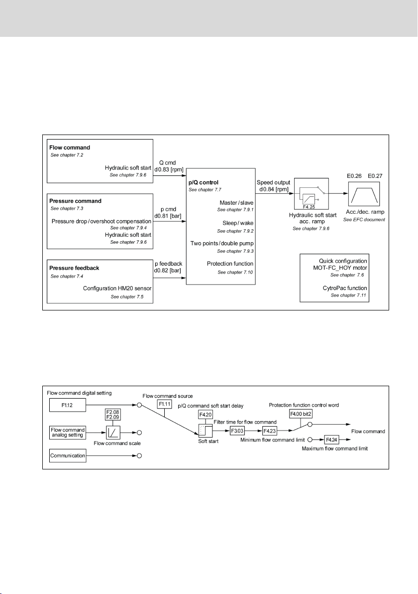
The following figure shows an overview of control functions in this ASF, for details information, reference the chapter number which is shown under each
function.
Fig. 7-1: p/Q PID control and relevant functions
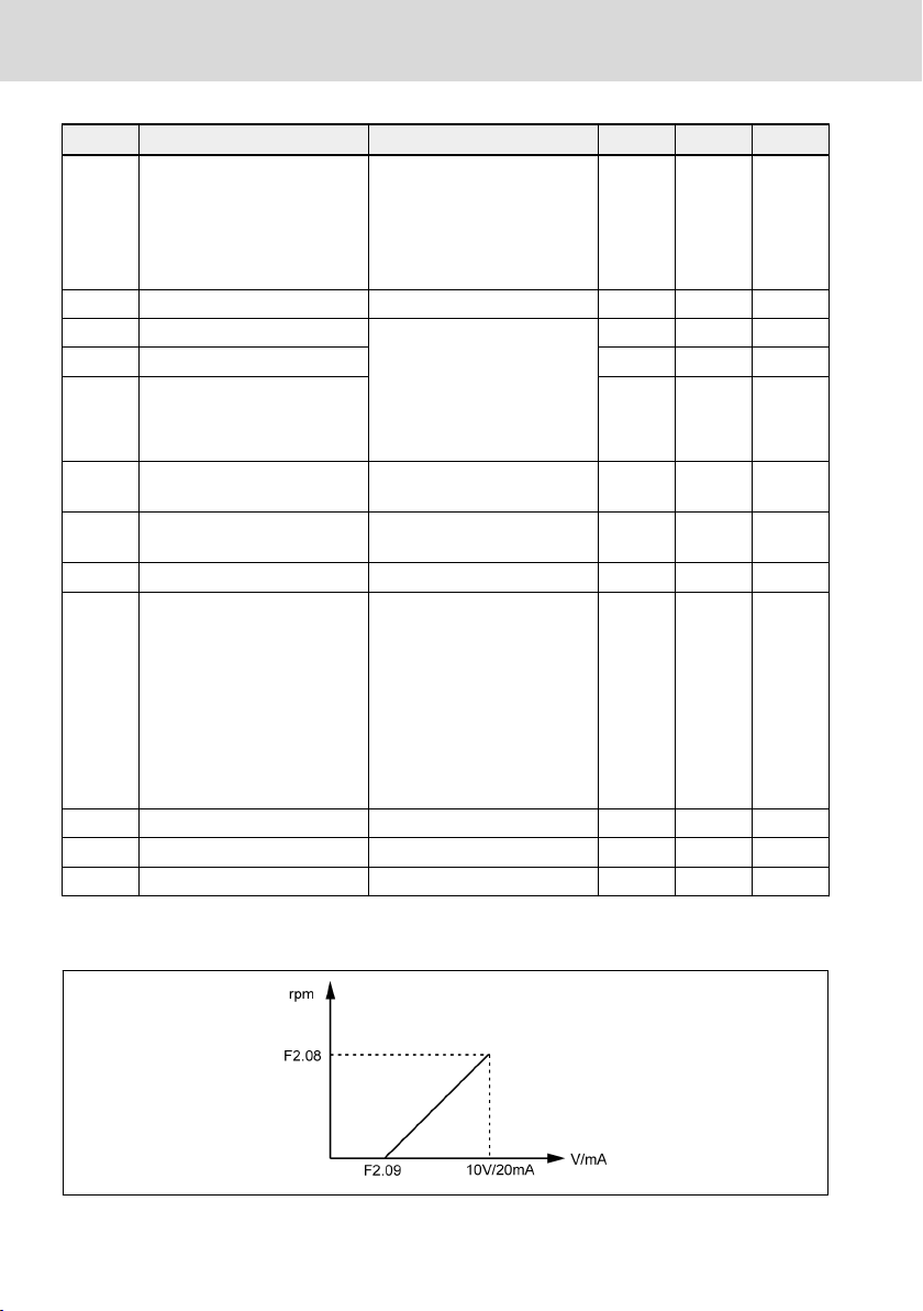
7.2 Flow Command Processing
Parameter F1.11 defines the source of flow command. The flow command value
can come from either predefined FcP 5020 parameters, analog input or using
fieldbus communication.
Fig. 7-2: Flow command processing
DOK-RCON03-FCP5020****-QU02-EN-P
17/75
Bosch Rexroth AG
FcP 5020
Block Diagram of Main Functions
Code Name Setting range Default Min. Attri.
0: Depend on the value of
F1.12
F1.11 Flow command source
1: Analog input (positive /
0 - Stop
negative)
2: Communication
F1.12 Flow command digital setting 0...5,000 rpm 400 1 Run
F2.00 Analog input AI1 0: No function assigned from
F2.01 Analog input AI2 2 - Stop
ASF
0 - Stop
1: Pressure command
F2.02
F2.08
F2.09
External analog input EAI
(-10V...10V, 4...20mA)
Flow command corresponding to 10V or 20mA
Flow command null offset in V
or mA
2: Pressure feedback
0 - Stop
3: Flow command
1...5,000 rpm 400 1 Stop
0.0...5.0 V, mA 0.0 0.1 Stop
F3.03 Filter time for flow command 0...999 ms 4 1 Run
0...15
Bit0: Pressure sensor failure
(PSF)
F4.00
Protection function control
word
Bit1: Actual pressure moni-
toring
0 - Run
Bit2: p/Q max. command lim-
it
Bit3: Oil changing detection
F4.20 p/Q command soft start delay 0.0...1,000.0 s 0.0 0.1 Stop
F4.23 Minimum flow command limit 0...[F4.24] rpm 200 1 Stop
F4.24 Maximum flow command limit [F4.23]...5,000 rpm 3,000 1 Stop
Tab. 7-1: Parameter list of flow command processing
F2.08, F2.09: Scaling for flow command
Fig. 7-3:
18/75
Flow command scaling
DOK-RCON03-FCP5020****-QU02-EN-P
FcP 5020 Bosch Rexroth AG
Block Diagram of Main Functions
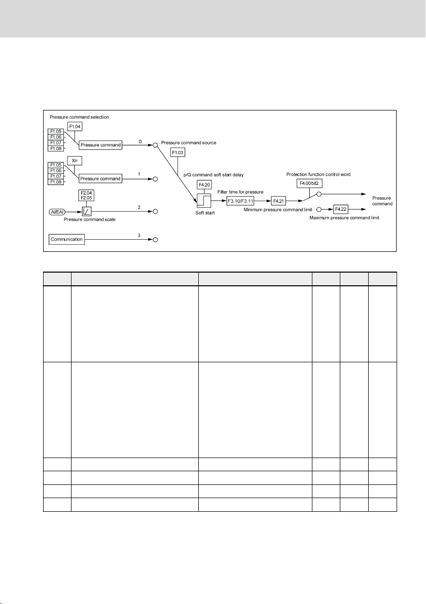
7.3 Pressure Command Processing
Pressure command can be generated from multiple sources such as predefined
in the parameters, analog input or fieldbus communication. User needs to define
the pressure command source prior to start up the system.
Fig. 7-4: Pressure command processing
Code Name Setting range Default Min. Attri.
0: Depend on the value of
F1.04
F1.03 Pressure command source
F1.04 Pressure command selection
F1.05 Pressure command digital setting 0 0.0...1,000.0 bar 10.0 0.1 Run
F1.06 Pressure command digital setting 1 0.0...1,000.0 bar 10.0 0.1 Run
F1.07 Pressure command digital setting 2 0.0...1,000.0 bar 10.0 0.1 Run
F1.08 Pressure command digital setting 3 0.0...1,000.0 bar 10.0 0.1 Run
1: Select by digital input (F1.04
shows status)
2: Analog input
3: Communication
0: Pressure command digital
setting 0
1: Pressure command digital
setting 1
2: Pressure command digital
setting 2
3: Pressure command digital
setting 3
0 - Stop
0 - Run
DOK-RCON03-FCP5020****-QU02-EN-P
19/75
Bosch Rexroth AG
FcP 5020
Block Diagram of Main Functions
Code Name Setting range Default Min. Attri.
F2.00 Analog input AI1 0: No function assigned from
F2.01 Analog input AI2 2 - Stop
ASF
0 - Stop
1: Pressure command
External analog input EAI (-10V...
F2.02
10V, 4...20mA)
Pressure command corresponding
F2.04
to 10V or 20mA
Pressure command null offset in V
F2.05
or mA
2: Pressure feedback
0 - Stop
3: Flow command
0.1...1,000.0 bar 10.0 0.1 Stop
0.0...5.0 V, mA 0.0 0.1 Stop
F3.10 Filter time for pressure rising [0] 0...999 ms 80 1 Run
Filter time for pressure dropping
F3.11
[0]
0...999 ms 40 1 Run
0...15
Bit0: Pressure sensor failure
(PSF)
F4.00 Protection function control word
Bit1: Actual pressure monitor-
0 - Run
ing
Bit2: p/Q max. command limit
Bit3: Oil changing detection
F4.20 p/Q command soft start delay 0.0...1,000.0 s 0.0 0.1 Stop
F4.21 Minimum pressure command limit 0.0...[F4.22] bar 5.0 0.1 Stop
F4.22 Maximum pressure command limit [F4.21]...1,000.0 bar 250.0 0.1 Stop
Tab. 7-2: Parameter list of pressure command processing
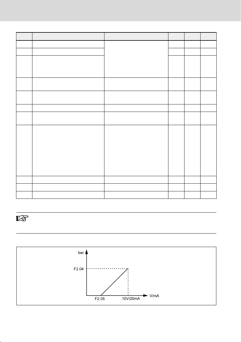
The setting is equally applicable to another parameter group related
to filter time for pressure command rising and dropping, i.e. F3.30,
F3.31.
F2.04, F2.05: Scaling for pressure command
Fig. 7-5: Pressure command scaling
20/75
DOK-RCON03-FCP5020****-QU02-EN-P
 Loading...