

Bosch Rexroth Servodyn-D Maintenance Manuallines
Over 100 years cumulative experience
24 hour rush turnaround / technical support service
Established in 1993
The leading independent repairer of servo motors and drives in North America.
Visit us on the web:
www.servo-repair.com
www.servorepair.ca
www.ferrocontrol.com
www.sandvikrepair.com
www.accuelectric.com
Scroll down to view your document!
For 24/7 repair services :
USA: 1 (888) 932 - 9183
Canada: 1 (905) 829 -2505
Emergency After hours: 1 (416) 624 0386
Servicing USA and Canada
Industrial
Hydraulics
Electric Drives
and Controls
Linear Motion
Assembly Technologies
Pneumatics
Service
Automation
Mobile
Hydraulics
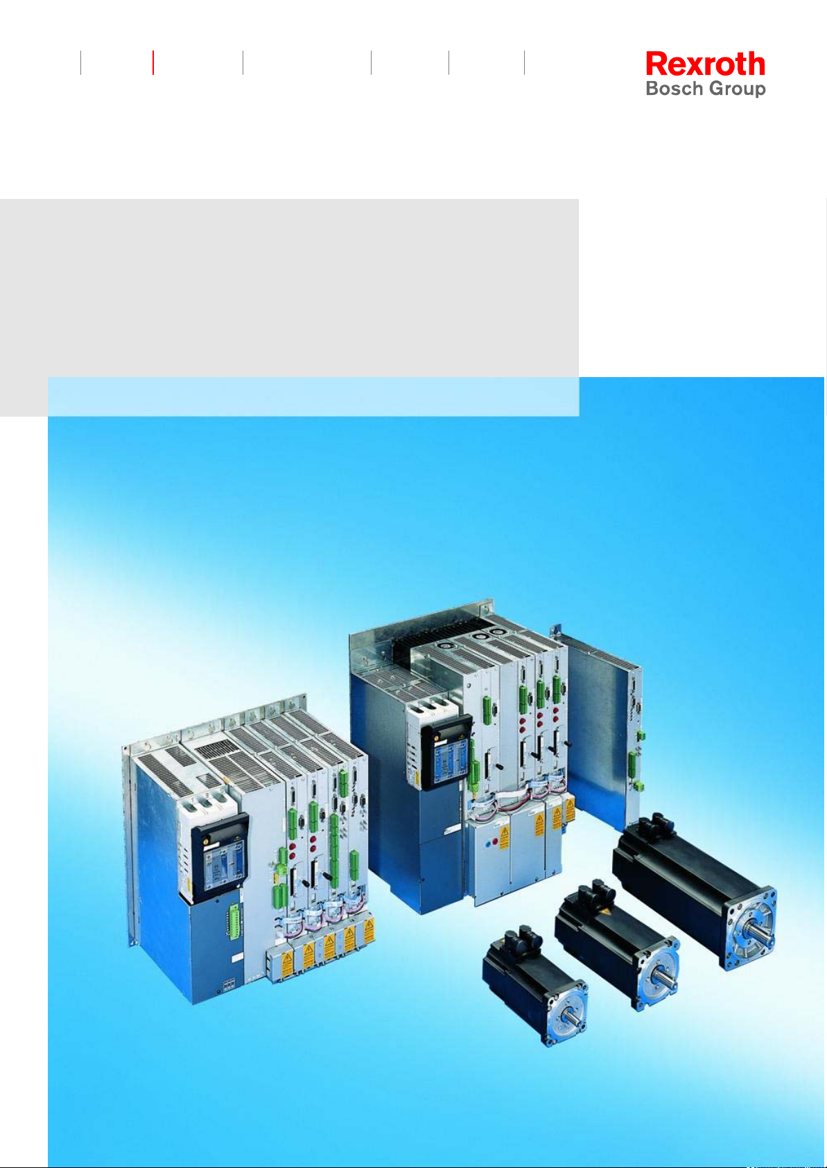
Rexroth ServodynD
Diagnostics, maintenance
Maintenance Guidelines
1070 066 032
Ausgabe 03
II Electric Drives
Bosch Rexroth AG Servodyn-D 1070 066 032 / 03
and Controls
Title
Type of Documentation
Document Typecode
Purpose of Documentation
Record of Revisions
Copyright
Rexroth Servodyn-D
Diagnostics, maintenance
Maintenance Guidelines
DOK-SERV*D-DIAGNOSTICS-WA03-EN-P
The present manual informs you about the diagnostics options of the
Servodyn-D drive series.
Description Release
Date
DOK-SERV*D-DIAGNOSTICS-WA03-EN-P 07.2003 Software
Notes
releases refer
to page 1–10
E Bosch Rexroth AG, 1998 – 2003
Copying this document, giving it to others and the use or
communication of the contents thereof without express authority, are
forbidden. Offenders are liable for the payment of damages. All rights
are reserved in the event of the grant of a patent or the registration
of a utility model or design (DIN 34–1).
Validity
Published by
The specified data is for product description purposes only and
may not be deemed to be guaranteed unless expressly confirmed
in the contract. All rights are reserved with respect to the content
of this documentation and the availability of the product.
Bosch Rexroth AG
Postfach 11 62
D-64701 Erbach
Berliner Straße 25
D-64711 Erbach
Tel.: +49 (0) 60 62/78-0
Fax: +49 (0) 60 62/78-4 28
Abt.:
BRC/ESM11 (WE)

Contents
Contents
Electric Drives
and Controls
Page
1 Safety Instructions 1–1 . . . . . . . . . . . . . . . . . . . . . . .
1.1 Intended use 1–1 . . . . . . . . . . . . . . . . . . . . . . . . . . . . . . . . . . . . . . . .
1.2 Qualified personnel 1–3 . . . . . . . . . . . . . . . . . . . . . . . . . . . . . . . . . .
1.3 Safety markings on products 1–4 . . . . . . . . . . . . . . . . . . . . . . . . . .
1.4 Safety instructions in this manual 1–5 . . . . . . . . . . . . . . . . . . . . . .
1.5 Safety instructions for the described product 1–6 . . . . . . . . . . . .
1.6 Documentation, software release and trademarks 1–9 . . . . . . .
2 Mains connection at the place of installation 2–1
2.1 Earthing 2–1 . . . . . . . . . . . . . . . . . . . . . . . . . . . . . . . . . . . . . . . . . . . .
2.2 Earth-leakage circuit-breaker 2–3 . . . . . . . . . . . . . . . . . . . . . . . . .
IIIBosch Rexroth AGServodyn-D1070 066 032 / 03
3 Marks, certifications 3–1 . . . . . . . . . . . . . . . . . . . . . .
3.1 CE-marking 3–1 . . . . . . . . . . . . . . . . . . . . . . . . . . . . . . . . . . . . . . . . .
3.2 EU design type certification 3–2 . . . . . . . . . . . . . . . . . . . . . . . . . . .
3.3 UL/CSA certification 3–3 . . . . . . . . . . . . . . . . . . . . . . . . . . . . . . . . .
4 Diagnostics displays at the drive 4–1 . . . . . . . . . .
4.1 VMA..KB, VMA..KE status, warning and error displays 4–1 . . .
4.2 VMA..KR, VMA..B,C,D,F status displays 4–2 . . . . . . . . . . . . . . .
4.3 VMA..KR, VMA..B,C,D,F warning displays 4–3 . . . . . . . . . . . . . .
4.4 Status displays DM and DS (without frequency inverter) 4–4 . .
4.5 VMA..KR, VMA..B,C,D,F and DM/DS error displays
(without frequency inverter) 4–5 . . . . . . . . . . . . . . . . . . . . . . . . . . .
4.5.1 List of error number in parameter P-0-0095 4–14 . . . . . . . . . . .
4.6 PROFIBUS-DP errors 4–28 . . . . . . . . . . . . . . . . . . . . . . . . . . . . . . . .
4.7 DMA computer errors (without SERCOS interface) 4–28 . . . . . .
4.8 Servodyn-D frequency inverter displays 4–29 . . . . . . . . . . . . . . . .
4.8.1 Status/warning displays 4–29 . . . . . . . . . . . . . . . . . . . . . . . . . . . . .
4.8.2 Error displays 4–31 . . . . . . . . . . . . . . . . . . . . . . . . . . . . . . . . . . . . .
5 Connection overview 5–1 . . . . . . . . . . . . . . . . . . . . .
5.1 VMA..KB, VMA..KE supply module
(with ballast switch) 5–1 . . . . . . . . . . . . . . . . . . . . . . . . . . . . . . . . . .
5.2 VMA..KR, VMA..B,C,D,F supply module
(with current regeneration) 5–2 . . . . . . . . . . . . . . . . . . . . . . . . . . . .
5.3 DMA module with analog interface or
positioning function (MC) 5–3 . . . . . . . . . . . . . . . . . . . . . . . . . . . . .
5.4 DMA module with SERCOS interface 5–4 . . . . . . . . . . . . . . . . . .
5.5 DMA module with CAN bus 5–5 . . . . . . . . . . . . . . . . . . . . . . . . . . .
5.6 DMA module with PROFIBUS-DP 5–6 . . . . . . . . . . . . . . . . . . . . .
5.7 DM..8001-D frequency inverter with analog interface 5–7 . . . . .
5.8 Stand-alone module DS, supply unit 5–8 . . . . . . . . . . . . . . . . . . .
5.8.1 Overview of DS..K xxx2-D (in set–up mode) 5–8 . . . . . . . . . . .

IV Electric Drives
Contents
Bosch Rexroth AG Servodyn-D 1070 066 032 / 03
and Controls
5.9 Overview of DS..K xxx1-D 5–9 . . . . . . . . . . . . . . . . . . . . . . . . . . . .
6 Replacing components 6–1 . . . . . . . . . . . . . . . . . . .
6.1 Motors 6–1 . . . . . . . . . . . . . . . . . . . . . . . . . . . . . . . . . . . . . . . . . . . . .
6.2 Drive modules 6–3 . . . . . . . . . . . . . . . . . . . . . . . . . . . . . . . . . . . . . .
6.2.1 VM...K and DM...K 6–3 . . . . . . . . . . . . . . . . . . . . . . . . . . . . . . . . .
6.2.2 DC link connection of VMA..B,C,D and DMA..A,B,D
6.2.3 DC link connection of VMW..F and DMW..F
A Annex A–1 . . . . . . . . . . . . . . . . . . . . . . . . . . . . . . . . . . .
A.1 Index A–1 . . . . . . . . . . . . . . . . . . . . . . . . . . . . . . . . . . . . . . . . . . . . . .
with backplane modules 6–4 . . . . . . . . . . . . . . . . . . . . . . . . . . . .
with water cooling 6–5 . . . . . . . . . . . . . . . . . . . . . . . . . . . . . . . . . .

Safety Instructions
1 Safety Instructions
Please read this manual before commissioning the Servodyn-D drives.
Store this manual in a place to which all users have access at any time.
1.1 Intended use
This manual contains information required for the intended use of this
product.
The described low-voltage motors are intended for use in commercial
or industrial systems. They comply with the harmonized standards of
the VDE 0530/EN 60034 series. Their use in potentially explosive atmospheres is not admissible unless expressly permitted by additional
instructions.
Electric Drives
and Controls
1–1Bosch Rexroth AGServodyn-D1070 066 032 / 03
Air-cooled designs are rated for ambient temperatures ranging between
–20 to +40 _C, and an operating altitude of v 1000 m above sea level.
Rating plate specifications deviating from this standard must be strictly
observed. Conditions at the operating site must correspond to all specifications stated on the rating plate.
Low-voltage motors comprise components intended for integration into
machines as contemplated by the EU Declaration of Conformity, as defined by Machinery Directive (98/37/EC, 98/79/EC). Before putting the
motors into operation, ensure that the machine the motors are to be
installed in meets the stipulations of the Machinery Directive (note also
EN 60204-1).
The drive inverters described
D have been developed, manufactured, tested and documented in
compliance with the safety standards. These products normally pose
no danger to persons or property if they are used in accordance with
the handling stipulations and safety notes prescribed for their configuration, mounting, and proper operation.
D comply with the requirements of
D the EMC Directives (89/336/EEC, 93/68/EEC and 93/44/EEC)
D the EMC product standard EN 61800-3 + A11
D the Low-Voltage Directive (73/23/EEC)
D the harmonized standards EN 50178 (VDE 0160) and
EN 60146-1-1 (VDE 0558-11)
D are designed for operation in industrial environments, i.e.
D no direct connection to public low-voltage power supply,
D connection to the medium- or high-voltage system via a trans-
former.
In residential environments, in trade and commerce as well as small
enterprises class A equipment may only be used if the following warning is attached:

1–2 Electric Drives
Safety Instructions
Bosch Rexroth AG Servodyn-D 1070 066 032 / 03
and Controls
. This is a Class A device. In a residential area, this device may cause
radio interference. In such case, the user may be required to
introduce suitable countermeasures, and to bear the cost of the
same.
Before putting the drive inverters into operation, ensure that the machine
which the inverters are to be installed in meets the stipulations of the Machinery Directive (98/37/EC, 98/79/EC) and the EMC Directive
(89/336/EEC).
The faultless, safe functioning of the product requires proper transport,
storage, erection and installation as well as careful operation.

Safety Instructions
1.2 Qualified personnel
The requirements as to qualified personnel depend on the qualification
profiles described by ZVEI (central association of the electrical industry)
and VDMA (association of German machine and plant builders) in:
Weiterbildung in der Automatisierungstechnik
edited by: ZVEI and VDMA
MaschinenbauVerlag
Postfach 71 08 64
D-60498 Frankfurt.
The present manual is designed for drive specialists.
Programming, start and operation as well as the modification of program
parameters is reserved to properly trained personnel! This personnel
must be able to judge potential hazards arising from programming, program changes and in general from the mechanical, electrical, or electronic equipment.
Electric Drives
and Controls
1–3Bosch Rexroth AGServodyn-D1070 066 032 / 03
Interventions in the hardware and software of our products, unless described otherwise in this manual, are reserved to specialized Rexroth
personnel.
Tampering with the hardware or software, ignoring warning signs attached to the components, or non-compliance with the warning notes
given in this manual may result in serious bodily injury or damage to
property.
Only electrotechnicians as recognized under IEV 826-09-01 (modified)
who are familiar with the contents of this manual may install and service
the products described.
Such personnel are
D those who, being well trained and experienced in their field and famil-
iar with the relevant norms, are able to analyze the jobs being carried
out and recognize any hazards which may have arisen.
D those who have acquired the same amount of expert knowledge
through years of experience that would normally be acquired through
formal technical training.
With regard to the foregoing, please note our comprehensive range of
training courses. Please visit our website at
http://www.boschrexroth.com
for the latest information concerning training courses, teachware and
training systems. Personal information is available from our Didactic
Center Erbach,
Telephone: (+49) (0) 60 62 78-600.
1–4 Electric Drives
Safety Instructions
Bosch Rexroth AG Servodyn-D 1070 066 032 / 03
and Controls
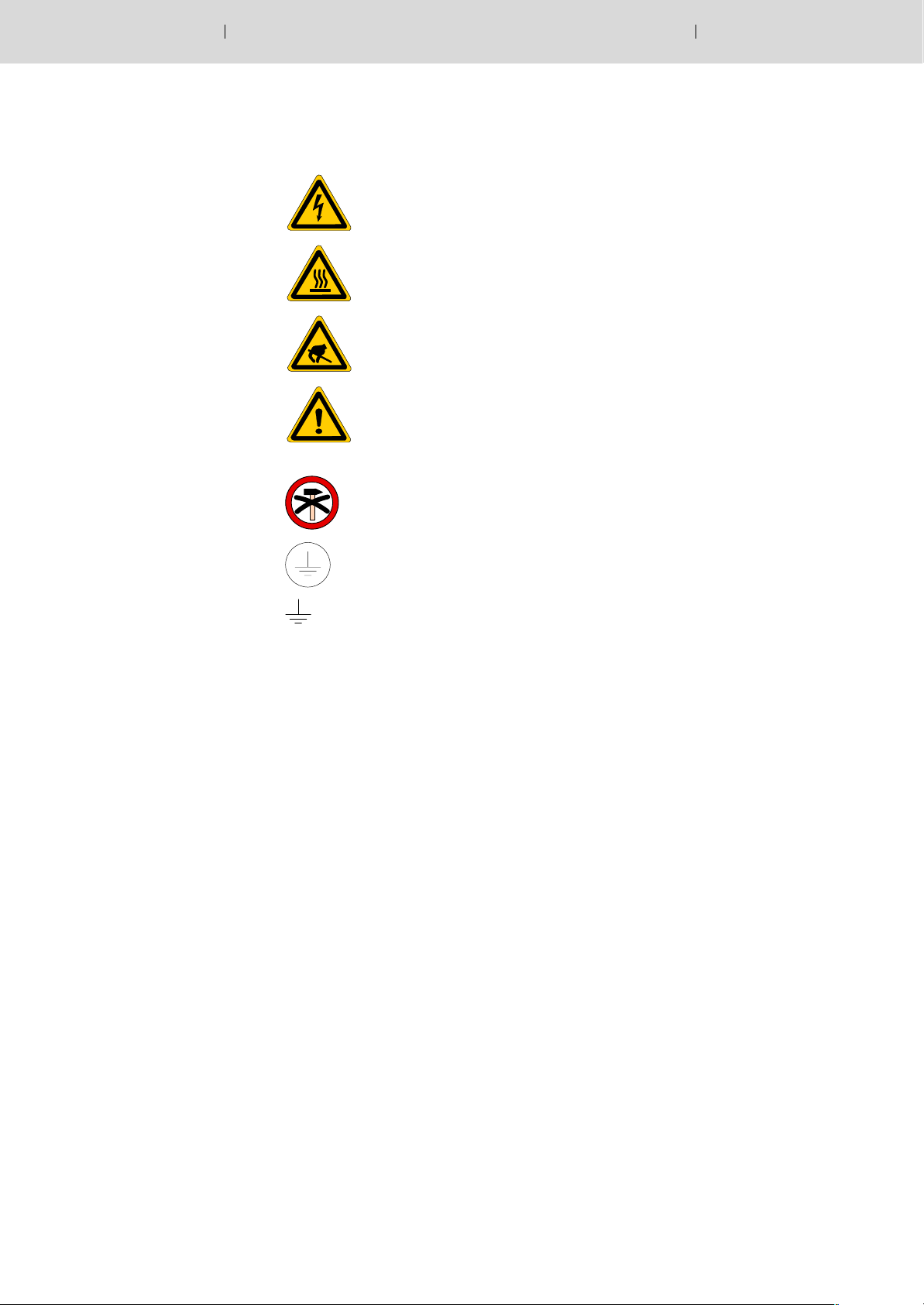
1.3 Safety markings on products
Warning of dangerous electrical voltage!
Warning of hot surface > 60 _C!
Electrostatically sensitive components!
Warning of hazardous light emissions
(optical fiber cable emissions)!
Protect against shock and impact!
Lug for connecting PE conductor only!
Connection of shield conductor only
. The hazard signs
– “Warning of dangerous electrical voltage”, and
– “Warning of hot surface”
supplied together with the motors must be attached to the motors
after installation in a visible location in accordance with the Machinery Directive (98/37/EC, 98/79/EC) if motor surfaces are exposed.
Safety Instructions
1.4 Safety instructions in this manual
DANGEROUS ELECTRICAL VOLTAGE
This symbol is used to warn of a dangerous electrical voltage. The
failure to observe the instructions in this manual in whole or in part may
result in personal injury.
DANGER
This symbol is used wherever insufficient or lacking compliance with instructions may result in personal injury.
Electric Drives
and Controls
1–5Bosch Rexroth AGServodyn-D1070 066 032 / 03
CAUTION
This symbol is used wherever insufficient or lacking compliance with instructions may result in damage to equipment or data files.
. This symbol is used to draw the user’s attention to special circum-
stances.
L This symbol is used if user activities are required.
1–6 Electric Drives
Safety Instructions
Bosch Rexroth AG Servodyn-D 1070 066 032 / 03
and Controls
1.5 Safety instructions for the described product
DANGER
Danger of life through inadequate EMERGENCY-STOP devices!
EMERGENCY-STOP devices must be active and within reach in all
system modes. Releasing an EMERGENCY-STOP device must not
result in an uncontrolled restart of the system!
First check the EMERGENCY-STOP circuit, then switch the system on!
DANGER
Danger for persons and equipment!
Test every new program before starting up a system!
DANGER
Retrofits or modifications may adversely affect the safety of the
products described!
The consequences may include severe injury, damage to equipment, or environmental hazards. Possible retrofits or modifications to the system using third-party equipment therefore have to
be approved by Rexroth.
DANGER
Health hazards through destroyed electrical components!
Do not destroy any built-in components. Dispose of destroyed
components in a proper manner.
DANGER
Do not look directly into the LEDs in the optical fiber connection.
Due to their high output, this may result in eye injuries.
When the inverter is switched on, do not look into the LED or the
open end of a short connected lead.
DANGER
Please note your local, system-specific regulations and requirements as well as the proper use of tools, hoisting and transport
equipment as well as the applicable standards, regulations, and
accident prevention regulations.
Safety Instructions
Electric Drives
and Controls
1–7Bosch Rexroth AGServodyn-D1070 066 032 / 03
DANGEROUS ELECTRICAL VOLTAGE
Unless described otherwise, maintenance works must be performed on inactive systems! The system must be protected
against unauthorized or accidental reclosing.
Measuring or test activities on the live system are reserved to
qualified electrical personnel!
DANGEROUS ELECTRICAL VOLTAGE
Lethal voltages of up to 375 V DC against ground on all power connections and DC link connections!
The drives must not be switched on unless all covers have been
fitted! When the drive has been disconnected from mains, wait for
up to 5 minutes until the system is de-energized before removing
any covers.
The drive must always be examined for safe isolation from supply!
DANGER – WARNING OF HOT SURFACE!
The surfaces of motors can reach temperatures of up to approx.
100 _C.
A touch guard is to be provided where necessary.
CAUTION
Impacts and shocks applied to the shaft end will damage the rotary
encoder and ball bearings!
Drive elements such as pulleys, clutch disks, toothed wheels etc.
may only be assembled or removed by continuously heating up
the drive elements or with a suitable installation or removal tool.
Use the thread in the shaft end.
CAUTION
use only spare parts approved by Rexroth!
CAUTION
Damages to the module or inverter by removing plug-in connections.
All plug-in connections to the encoder may only be inserted or removed while the drive is switched off.

1–8 Electric Drives
Safety Instructions
Bosch Rexroth AG Servodyn-D 1070 066 032 / 03
and Controls
CAUTION
Observe all precautions for ESD protection when handling modules and components! Avoid electrostatic discharge!
The following protective measures must be observed for modules and
components sensitive to electrostatic discharge (ESD)!
D Personnel responsible for storage, transport, and handling must have
training in ESD protection.
D ESD-sensitive components must be stored and transported in the
prescribed protective packaging.
D ESD-sensitive components may only be handled at special ESD-
workplaces.
D Personnel, working surfaces, as well as all equipment and tools
which may come into contact with ESD-sensitive components must
have the same potential (e.g. by grounding).
D Wear an approved grounding bracelet. The grounding bracelet must
be connected with the working surface through a cable with an integrated 1 MW resistor.
D ESD-sensitive components may by no means come into contact with
chargeable objects, including most plastic materials.
D When ESD-sensitive components are installed in or removed from
equipment, the equipment must be de-energized.
Electric Drives
and Controls
Safety Instructions
1.6 Documentation, software release and trademarks
Documentation
The present manual informs you about the diagnostics options of the
Servodyn-D drive series.
1–9Bosch Rexroth AGServodyn-D1070 066 032 / 03
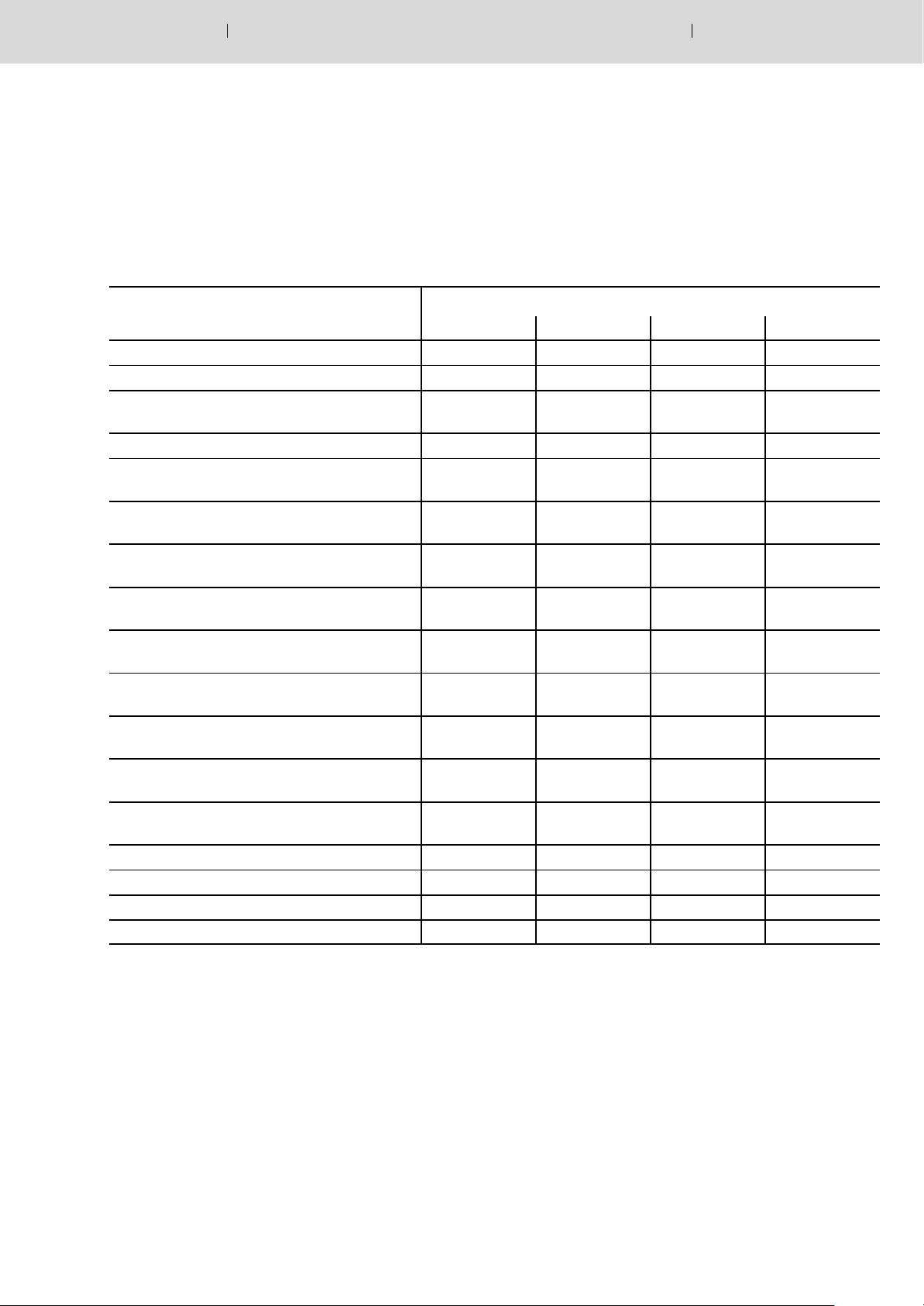
Overview of available documentation
Servo motors SF, SR 1070 066 004 1070 066 024 1070 066 048 1070 066 046
Asynchronous motors DU 1070 066 007 1070 066 027 – –
Servodyn-D, Configuration
- Manual for overview and rating
Servodyn-D, Connectivity Manual 1070 066 010 1070 066 030 1070 066 060 1070 066 050
Servodyn-D,
- Connectivity Manual - Stand alone version
Servodyn-D, Servodyn-M
- Parameter manual (without CANopen)
Servodyn-D, Servodyn-M
- Parameter manual CANopen
Servodyn-D with SERCOS interface
- Parameter and commissioning manual
Servodyn-D with analog interface
- Commissioning manual
Servodyn-D with CANrho interface
- Commissioning manual
Servodyn-D with motion control
- Commissioning manual
Servodyn-D with PROFIBUS-DP
- Commissioning manual
Servodyn-D DM/DS..8001 (ASM)
Parameter and commissioning manual
Diagnostics, maintenance 1070 066 012 1070 066 032 1070 066 062 1070 066 052
RSU, Redundant safety monitoring 1070 066 006 1070 066 026 1070 066 081 1070 066 082
EMC manual 1070 066 072 1070 066 074 1070 066 075 1070 066 076
External load switching module EBX 1070 066 077 1070 066 080 – –
Part no.
German English French Italian
1070 066 009 1070 066 029 1070 066 059 1070 066 049
1070 066 016 1070 066 036 1070 066 066 1070 066 056
1070 066 018 1070 066 038 1070 066 068 1070 066 058
1070 066 094 1070 066 095 – –
1070 066 011 1070 066 031 – 1070 066 051
1070 066 014 1070 066 034 – –
1070 066 017 1070 066 037 – –
1070 066 015 1070 066 035 – –
1070 066 090 1070 066 091 – –
1070 066 008 1070 066 028 – 1070 066 053
. In this manual the floppy disk drive always uses drive letter A:, and
the hard disk drive always uses drive letter C:.
Special keys or key combinations are shown enclosed in pointed brackets:
D Named keys: e.g., <Enter>, <PgUp>, <Del>
D Key combinations (pressed simultaneously): e.g., <Ctrl> + <PgUp>

1–10 Electric Drives
Safety Instructions
Bosch Rexroth AG Servodyn-D 1070 066 032 / 03
and Controls
Release
. The present manual applies to the following releases:
DM/DS software: SERCOS interface V0.049 or higher
VM software: V0.045 or higher
D The current software release number can be viewed by selecting
parameter S-0-0030 with the DSS-D Commissioning and Service
System, or in the ”Software” field of the module configuration display
(DIAGNOSTICS " MODULE CONFIGURATION).
D For information concerning the current DSS software release, refer to
HELP " ABOUT...
CANopen/rho V0.002 or higher
Analog interface V0.17 or higher
PROFIBUS-DP V0.004 or higher
Motion Control V0.010 or higher
Trademarks
D The current software release of VMA..KR and VMA..B,C,D,F can
only be read from the 7-segment display during test operation. For
this purpose, turn dip switch ”T” on the VM’s personality module ”on”:
The following appears in a running, flashing display:
“Cxx.ZZ.ddmmyyyy“
Where: xx = software release number
ZZ = (internal)
dd = software creation day
mm = software creation month
yyyy = software creation year
All trademarks of software installed on Rexroth products upon delivery
are the property of the respective manufacturer.
Upon delivery, all installed software is copyright-protected. The software
may only be reproduced with the approval of Rexroth or in accordance
with the license agreement of the respective manufacturer.
MS-DOSr and Windowst are registered trademarks of Microsoft
Corporation.
PROFIBUSr
is a registered trademark of the PROFIBUS Nutzerorgani-
sation e.V. (user organization).
SERCOS interfacet is a registered trademark of Interessengemeinschaft SERCOS interface e.V. (Joint VDW/ZVEI Working Committee).
Electric Drives
and Controls
Mains connection at the place of installation
2 Mains connection at the place of installation
CAUTION
A reversed phase sequence or winding direction of a line reactor
will destroy the mains connection module.
Please ensure proper wiring.
2.1 Earthing
CAUTION
Inverter modules may only be operated with an earthed neutral
system.
Systems not directly earthed (IT protective system) must not be
used for operation, as air clearances and leakage paths in the
module may be overloaded.
Operation at asymmetrical mains systems (TT protective system,
one mains phase is earthed) is not permissible!
2–1Bosch Rexroth AGServodyn-D1070 066 032 / 03
DIN VDE 0100-300 defines mains systems subject to their type of earth
connection.
Accordingly, in an IT protective system, all active parts are separated
from earth, or one point is connected to earth via a resistor.
The exposed conductive parts of an electrical system are either
D earthed separately, or
D earthed jointly, or
D jointly connected to the system earth.
. Please note the information on earthing in the Servodyn-D EMC
manual, for part no. refer to page 1–9.
DANGEROUS ELECTRICAL VOLTAGE
The only permissible protective measure in accordance with
EN 50 178 is a protective earth connection.
The protective conductor must at least have the same area as the
mains feeder.
Earthing only one end of the DC link when operating by means of
an isolating transformer is prohibited!
2–2 Electric Drives
Mains connection at the place of installation
Bosch Rexroth AG Servodyn-D 1070 066 032 / 03
and Controls
Earth connections in the switch cabinet must be designed in the form of a
grid mesh.
The module housing and mounting plate of the switch cabinet must be
earthed. The connection between the line filter and the supply module
should be as short as possible.
The protective earth cross-section must at least correspond to the crosssection of the line feeder of the supply module.
DANGER
Dangerous shock currents through inappropriate protective earth
connections!
Do not impair protective earth connections by mechanical, chemical or electro-chemical influences. The connection must be firm
and lasting.
Mains connection at the place of installation
2.2 Earth-leakage circuit-breaker
Inverters incorporate switched power units which are always associated
with capacitive leakage currents against earth. The leakage currents
may depend on the number of inverters, the earthing conditions as well
as the design and length of motor power cables.
Mains filters and shielded cables used to improve the electromagnetic
compatibility (EMC) increase the leakage currents further. For this reason, no earth-leakage circuit-breakers with nominal leakage currents of
less than 300 mA may be used.
DANGEROUS ELECTRICAL VOLTAGE
Personnel protection is only guaranteed if earth-leakage circuitbreakers with nominal leakage currents of less than 30 mA are
used.
Electric Drives
and Controls
2–3Bosch Rexroth AGServodyn-D1070 066 032 / 03
. Inductors and/or capacitors present in the electric circuit may lead
to spurious trips. If radio interference suppression filters are used,
spurious trips can only be avoided by installing an isolating transformer.
DANGEROUS ELECTRICAL VOLTAGE
If a pulse power current sensitive e.l.c.b. type A in accordance with
IEC-755 (VDE 0664) is used, its protective function is not guaranteed for inverters with a 3-phase mains connection (B6 circuit).
The protection of all electrical components connected together with inverters with a 3-phase mains connection to a pulse power current sensitive e.l.c.b. may be adversely affected.
Therefore, you should either install an isolating transformer with a protective device and earthing in the mains feeder, or use a universal current sensitive e.l.c.b. type B which also provides safety disconnection in
the event of DC leakage currents.

2–4 Electric Drives
Bosch Rexroth AG Servodyn-D 1070 066 032 / 03
and Controls
Mains connection at the place of installation
Notes:

Marks, certifications
3 Marks, certifications
3.1 CE-marking
Low-Voltage Directive
The CE marking confirms compliance of drive modules of the ServodynD series with the Low-Voltage Directive. The rating and construction satisfy the requirements of EN 50178.
Machinery Directive
The CE marking confirms compliance of drive modules of the ServodynD series with the Machinery Directive. The rating and construction satisfy the requirements of EN 60204-1.
Electric Drives
and Controls
3–1Bosch Rexroth AGServodyn-D1070 066 032 / 03
EMC Directive
Concerning the EMC Directive, the exception stipulated in the German
EMC Act, EMVG Art. 6, Subs. (9), is applicable, cf. below.
The following must be noted with respect to the operational system (cf.
EMC manual):
D Requirements on EMC noise emission
D Conducted noise
Depending on the application (industrial environment or domestic
application), a suitable mains filter is to be provided in the power
supply line.
The cubicle construction should be designed so as to ensure the
efficiency of the mains filter to the greatest possible extent.
D Radiated noise
Depending on the application (industrial environment or domestic
application), a suitable switch cabinet with EMC shielding has to
be provided.
For the motor leads, shielded cables should be preferably used
which are grounded on both ends of the shield.
D Required interference immunity
The rating and construction satisfy the requirements of the EMC
product standard EN 61800-3 for application in industrial environments.
EMVG 18.09.1998
Art. 6 Exceptions and special determinations
(9)Apparatuses, systems, and components covered by Subs. 3, which
are exclusively manufactured and designed as accessories or spare
parts for further processing by companies or persons with expert
knowledge in the field of electromagnetic compatibility, are exempted
from compliance with the protection requirements and the requirements of Art. 4 Subs. 1 Nos. 1 to 3 and 5. The operational unit which
contains apparatuses, systems or components defined in the 1
tence above, shall satisfy the provisions of this law.
st
sen-
3–2 Electric Drives
Marks, certifications
Bosch Rexroth AG Servodyn-D 1070 066 032 / 03
and Controls
3.2 EU design type certification
The certification covers Servodyn-D with redundant safety monitoring
RSU. RSU complies with the requirements concerning:
D Safety-relevant parts of controllers in accordance with EN 954-1
Category 3, as required by
D EN 12415 (safety of turning machines)
D EN 12417 (safety of machining centres)
D Control functions in the event of a fault according to EN 60204-1
In the special mode, the integrated 2-channel safety structure monitors
all axis and spindle movements. It is available for:
D Three-phase modules with SERCOS interface
(firmware release as of V0.040)
D in connection with supply modules with energy recovery capability
(firmware release as of V0.040) and
D mains connection module NAA
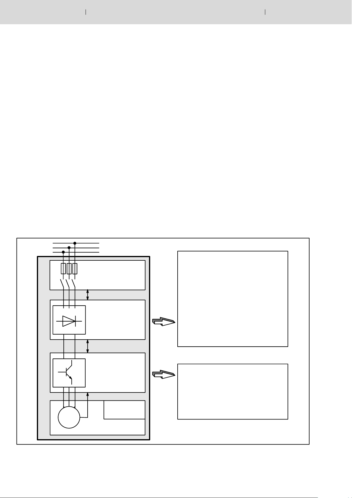
NAA mains connection module
Mains contactor control
Supply module VM
with sinusoidal infeed
and recovery
Sercodyn-D concept
Three-phase current
module DM
This concept has been certified, i.e. additional monitoring equipment is
not necessary.
. For more information, refer to Servodyn-D with Redundant Safety
Monitoring manual, part no. in Section 1.6.
Three-phase mains
D Integration of an EMERGENCY-
STOP switch
D Connection and monitoring of a
mode selector switch
D Connection and monitoring of a
dead-man’s key
D Integrated line monitor for single
and multiple phase mains failures
D Integrated control and monitoring
of the protective door tumbler
Module crosscon
nection
D Safe reduced speed in special mode
Motor
Safety
tumbler
Separating protective
device
D Safe standstill in special mode
D Monitoring of the maximum speed

Marks, certifications
3.3 UL/CSA certification
For a number of Servodyn-D modules in compact mechanics, a UL/CSA
certification is available for the U.S. and Canada. They are marked by
adhesive labels. These modules are listed in the ”Product Identity 23
MB”, File No. E214694.
Installation in compliance with UL/CSA
In order to obtain a UL/CSA-compliant installation, the following must be
noted in addition to the use of the certified components:
D Systems may only be used in environments with pollution severity 2.
D Note tightening torques of the connection terminals as specified in In-
terface Conditions manual, for part no. refer to page 1–9.
D The insulated wires must be specified for 60/75_C as a minimum.
D Only insulated Class 1 wires or equivalent may be used,
e.g. to UL Style 1015 (on motor side, H07: U
Style 1007 or 1569 (on supply side, H05: U
D Suitable for installation in symmetrical supply networks with a short-
circuit current of x 10 kA with max. 460 V +10 %.
Electric Drives
and Controls
/U: 600/1000 V) and UL
0
/U: 300/500 V)
0
3–3Bosch Rexroth AGServodyn-D1070 066 032 / 03
Operation in compliance with UL/CSA
For UL/CSA-compliant operation, the bimetal function (I
must be activated in the inverters using parameter P-0-0053 in order to
provide motor protection.
of the motor is automatically retrieved from the electronic rating
D I
N
plate to the I
D P-0-0053 is only used to set the desired time constant:
Factory setting: 0.0 (disabled)
Customary setting range: 100...150
2
t monitoring function.
(corresponds to release characteristics of
bimetal relay)
2
t monitoring)

3–4 Electric Drives
Bosch Rexroth AG Servodyn-D 1070 066 032 / 03
and Controls
Marks, certifications
Notes:
 Loading...