

Bosch Rexroth Rho 4.0 System Description
Industrial
Hydraulics
Electric Drives
and Controls
Linear Motion and
Assembly Technologies Pneumatics
Service
Automation
Mobile
Hydraulics
Rexroth Rho 4.0
System description
1070072367
Edition 04
Project planning

II Electric Drives
Bosch Rexroth AG RhoMotion 1070072367 / 04
and Controls
Title
Type of Documentation
Document Typecode
Purpose of Documentation
Record of Revisions
Rexroth Rho 4.0
System description
Project planning
DOK-RHO*4*-RHO4.0*SYSB-PR04-EN-P
The present manual informs about:
D structures, functionalities and
D programming of the rho4.0
Description Release
Date
DOK-RHO*4*-RHO4.0*SYSB-PR03EN-P
DOK-RHO*4*-RHO4.0*SYSB-PR04EN-P
10.2003 Valid from VO07
01.2005 Valid from VO08
Notes
Copyright
Validity
Published by
E Bosch Rexroth AG, 1998 − 2005
Copying this document, giving it to others and the use or
communication of the contents thereof without express authority, are
forbidden. Of fenders are liable for the payment of damages. All rights
are reserved in the event of the grant of a patent or the registration
of a utility model or design (DIN 34−1).
The specified data is for product description purposes only and
may not be deemed to be guaranteed unless expressly confirmed
in the contract. All rights are reserved with respect to the content
of this documentation and the availability of the product.
Bosch Rexroth AG
Postfach 11 62
D-64701 Erbach
Berliner Straße 25
D-64711 Erbach
Tel.: +49 (0) 60 62/78-0
Fax: +49 (0) 60 62/78-4 28
Abt.:
BRC/ESH (KW)
Overview of all manuals
Connection conditions Rho 4.0
System description Rho 4.0
Connection conditions Rho4.1,
Connection conditions
4.1/BT155T, Rho 4.1/BT205
System description Rho 4.1
Overview of all manuals
Manual Contents
Electric Drives
and Controls
IIIBosch Rexroth AGRhoMotion1070072367 / 04
Connection conditions Rho 4.0
System description Rho 4.0
Connection conditions Rho4.1,
Rho 4.1/IPC300
2 System overview
3 Installation
4 Electrical connection
5 Interfaces
6 LED display
7 Maintenance and replacement
8 Order numbers
2 System overview
3 Structure of the rho4.0
4 PCLrho4.0
5 CAN-Bus peripheral unit
6 SERCOS interface
7 Software
8 File management
2 System overview
3 Security functions
4 Installation
Connection conditions
Rho 4.1/BT155, Rho
System description Rho 4.1
5 Electrical connection
6 Interfaces
7 LED display
8 Maintenance and replacement
9 Software
10 Order numbers
2 System overview
3 Security functions
4 Installation
5 Electrical Connections
6 Interfaces
7 Display and Operating Controls
8 Maintenance and Replacemant
9 Software
10 Order numbers
2 Structure of the rho4.1
3 PCL
4 CAN-Bus peripheral unit
5 SERCOS interface
IV Electric Drives
Control functions
Machine parameters
Bosch Rexroth AG RhoMotion 1070072367 / 04
and Controls
Overview of all manuals
Manual Contents
6 Software
7 File management
8 Scope of the rho4.1 Software
Manual Contents
Control functions
2 Survey of special functions
3 Accurate position switching
4 Setting the machine position
5 Calling operating system functions
6 Parameterization of the belt characte-
ristic
7 Selecting a point-file
8 Mirroring
9 Belt type
10 System date and time
11 System counter
12 WC main range
13 Setting the belt counter
14 Recording of reference path
15 Flying measurement (rho4.1 only)
16 MOVE_FILE
17 Setting the block preparation
18 Exception−Handling
Machine parameters
19 Belt counter current value
20 Automatic velocity adjustment for PTP
movements
21 Belt-synchronous working area belt
kind 4
22 Current belt speed
23 Changing the belt simulation speed
24 General functions
25 Process-oriented functions
26 BAPS3 keywords
2 General information
3 Application of the machine parameters
4 General system parameters
5 Speeds
6 Positions
7 Kinematic parameters
Overview of all manuals
BAPS3 Programming manual
BAPS3 Short description
Signal descriptions
Status messages
ROPS4/Online
Electric Drives
and Controls
Manual Contents
8 Measuring system parameters
9 Belt parameters
10 Drive parameters Servodyn-GC
11 Drive parameter Servodyn-D
12 Table of parameters
Manual Contents
VBosch Rexroth AGRhoMotion1070072367 / 04
BAPS3 Programming manual
BAPS3 Short description
2 Program structure
3 Constants
4 Variables
5 Program control
6 Value assignments and combinations
7 Functions
8 Movement statement
9 Write/read functions
10 BAPS3 keywords
2 Program structure
3 Constants and variables
4 Program structure
5 Value assignments and combinations
6 Standard functions
7 Movements and speeds
8 Belt synchronous
9 Workspace limitation
Signal descriptions
Status messages
and warnings
ROPS4/Online
10 Write/read functions
11 Special functions
12 Library functions
13 Fix files
14 BAPS3 keywords
2 rho4 interface description
3 Signal description of PCL inputs
4 Signal description of PCL outputs
2 rho4 status messages
3 Warnings
4 CANopen error codes
2 General information
3 Activation and functions of Online
4 The function key box

VI Electric Drives
DLL library
Connection conditions
Bosch Rexroth AG RhoMotion 1070072367 / 04
and Controls
Overview of all manuals
Manual Contents
5 Function key assignment
6 The marker box
7 File ROPS4WIN.ini
8 Selection of a file
9 TCP/IP settings for ROPS4
Manual Contents
DLL library
PHG2000
2 Library functions
3 Calling library functions in BAPS
4 Block structure of the rho4.1
5 Library server
6 Application development
7 rho4 library functions
8 Variable access per DLL
2 Hand-held programming unit
PHG2000
3 PHG2000 system variables
4 Selection of PHG functions
5 Info function of the PHG
6 Controlling the PHG2000 output
7 Define/Teach
8 SRCAN functions
9 File and User Memory Functions
10 File list
11 Process info
Connection conditions
Rho 4.1/IPC 40.2
12 Restoring the PGH display
13 Variable assignment of PHG keys
14 Select point file and point name
15 BDT editor
2 System Overview
3 Security Functions
4 Installation
5 Eelectrical Connections
6 Interface Ports & Connectors
7 Display- and Operating Components
8 Maintenance and Replacement
9 Software
10 Ordering Informations

Overview of all manuals
DDE-Server
Electric Drives
and Controls
Manual Contents
VIIBosch Rexroth AGRhoMotion1070072367 / 04
DDE-Server
2 Introduction
3 Hardware and Software
4 Operation
5 Items of Server 4
6 Scope of function

VIII Electric Drives
Bosch Rexroth AG RhoMotion 1070072367 / 04
and Controls
Overview of all manuals
Notes:

Contents
Contents
Electric Drives
and Controls
1 Safety Instructions 1−1 . . . . . . . . . . . . . . . . . . . . . . .
1.1 Intended use 1−1 . . . . . . . . . . . . . . . . . . . . . . . . . . . . . . . . . . . . . . . .
1.2 Qualified personnel 1−2 . . . . . . . . . . . . . . . . . . . . . . . . . . . . . . . . . .
1.3 Safety markings on products 1−3 . . . . . . . . . . . . . . . . . . . . . . . . . .
1.4 Safety instructions in this manual 1−4 . . . . . . . . . . . . . . . . . . . . . .
1.5 Safety instructions for the described product 1−5 . . . . . . . . . . . .
1.6 Documentation, software release and trademarks 1−7 . . . . . . .
2 System overview 2−1 . . . . . . . . . . . . . . . . . . . . . . . . .
3 Structure of the rho4.0 3−1 . . . . . . . . . . . . . . . . . . .
3.1 Description of the structure 3−1 . . . . . . . . . . . . . . . . . . . . . . . . . . .
3.1.1 Outline structure 3−2 . . . . . . . . . . . . . . . . . . . . . . . . . . . . . . . . . . .
3.1.2 rho4.0 block diagramm 3−3 . . . . . . . . . . . . . . . . . . . . . . . . . . . . .
3.1.3 Operating system of the rho4.0 3−4 . . . . . . . . . . . . . . . . . . . . . .
3.1.4 Floppy operation 3−4 . . . . . . . . . . . . . . . . . . . . . . . . . . . . . . . . . . .
3.2 Digital I/O 3−8 . . . . . . . . . . . . . . . . . . . . . . . . . . . . . . . . . . . . . . . . . .
3.2.1 Digital inputs 3−8 . . . . . . . . . . . . . . . . . . . . . . . . . . . . . . . . . . . . . .
3.2.2 Digital outputs 3−12 . . . . . . . . . . . . . . . . . . . . . . . . . . . . . . . . . . . . .
3.3 Operation with I/O-Gateway 3−14 . . . . . . . . . . . . . . . . . . . . . . . . . .
3.3.1 rho4.0 without PCL field bus card 3−14 . . . . . . . . . . . . . . . . . . . .
3.3.2 Examples of B~IO M-CAN bus connections 3−15 . . . . . . . . . . .
3.3.3 rho4.0 with PCL field bus card 3−32 . . . . . . . . . . . . . . . . . . . . . . .
3.3.4 Example of a B~IO M-DP Profibus connection 3−33 . . . . . . . . .
3.3.5 Example of a B~IO M-IBS bus connection 3−34 . . . . . . . . . . . . .
3.3.6 Example of a B~IO M-CAN bus connection 3−34 . . . . . . . . . . . .
3.4 Fixed IP addresses 3−36 . . . . . . . . . . . . . . . . . . . . . . . . . . . . . . . . . .
3.5 Small linking with switches 3−37 . . . . . . . . . . . . . . . . . . . . . . . . . . . .
3.5.1 Cabling 3−37 . . . . . . . . . . . . . . . . . . . . . . . . . . . . . . . . . . . . . . . . . . .
3.5.2 Linking of two rho4.0 3−37 . . . . . . . . . . . . . . . . . . . . . . . . . . . . . . .
3.5.3 Smallest linking of up to 6 rho4.1 with 8-fold switch 3−38 . . . . .
3.5.4 Small linking of several rho4.0 with 8-fold switch 3−39 . . . . . . .
3.5.5 Remote control with ROPS4 and virtual PHG 3−41 . . . . . . . . . .
IXBosch Rexroth AGRhoMotion1070072367 / 04
Page
4 PCLrho4.0 4−1 . . . . . . . . . . . . . . . . . . . . . . . . . . . . . . .
4.1 PCLrho4.0 programming with WinSPS from version 3.1
(build 1406) 4−6 . . . . . . . . . . . . . . . . . . . . . . . . . . . . . . . . . . . . . . . . .
4.2 PCLrho4.0 configuration with WinDP from version 2.10
(build 677) 4−9 . . . . . . . . . . . . . . . . . . . . . . . . . . . . . . . . . . . . . . . . . .
4.3 PCLrho4.0 configuration with WinCAN 1.1 (build 92) 4−11 . . . . .
4.4 Operation of the PCLrho4.0 with INTERBUS-S 4−13 . . . . . . . . . .

X Electric Drives
Contents
Bosch Rexroth AG RhoMotion 1070072367 / 04
and Controls
5 CAN-Bus peripheral equipment 5−1 . . . . . . . . . . .
5.1 CANopen-Interface 5−1 . . . . . . . . . . . . . . . . . . . . . . . . . . . . . . . . . .
5.1.1 Functions 5−1 . . . . . . . . . . . . . . . . . . . . . . . . . . . . . . . . . . . . . . . . .
5.1.2 Machine parameters 5−2 . . . . . . . . . . . . . . . . . . . . . . . . . . . . . . .
5.2 CANopen-encoder 5−4 . . . . . . . . . . . . . . . . . . . . . . . . . . . . . . . . . .
5.2.1 Functions 5−4 . . . . . . . . . . . . . . . . . . . . . . . . . . . . . . . . . . . . . . . . .
5.2.2 Machine parameter 5−5 . . . . . . . . . . . . . . . . . . . . . . . . . . . . . . . .
5.3 CAN belts 5−9 . . . . . . . . . . . . . . . . . . . . . . . . . . . . . . . . . . . . . . . . . .
5.3.1 Functions 5−9 . . . . . . . . . . . . . . . . . . . . . . . . . . . . . . . . . . . . . . . . .
5.3.2 Machine parameters 5−9 . . . . . . . . . . . . . . . . . . . . . . . . . . . . . . .
5.4 CAN Interface X53 (only rho4.0L) 5−13 . . . . . . . . . . . . . . . . . . . . .
5.5 Analog I/O with CAN B~IO modules 5−14 . . . . . . . . . . . . . . . . . . .
5.5.1 Bus switching 5−14 . . . . . . . . . . . . . . . . . . . . . . . . . . . . . . . . . . . . .
5.5.2 Analog I/O modules 5−15 . . . . . . . . . . . . . . . . . . . . . . . . . . . . . . . .
5.5.3 Machine parameter settings 5−16 . . . . . . . . . . . . . . . . . . . . . . . . .
5.5.4 Analog I/O parameter 5−22 . . . . . . . . . . . . . . . . . . . . . . . . . . . . . .
5.5.5 Example 5−24 . . . . . . . . . . . . . . . . . . . . . . . . . . . . . . . . . . . . . . . . . .
5.5.6 BAPS-Program 5−28 . . . . . . . . . . . . . . . . . . . . . . . . . . . . . . . . . . . .
5.6 SR-CAN module 5−29 . . . . . . . . . . . . . . . . . . . . . . . . . . . . . . . . . . . .
5.7 Analog In-/Outputs of the SR-CAN module 5−35 . . . . . . . . . . . . .
5.7.1 CAN-bus switching 5−35 . . . . . . . . . . . . . . . . . . . . . . . . . . . . . . . . .
5.7.2 Measuring ranges and data formats 5−35 . . . . . . . . . . . . . . . . . .
5.7.3 Machine parameter settings 5−36 . . . . . . . . . . . . . . . . . . . . . . . . .
5.8 Assignment of the CAN-Bus interfaces 5−40 . . . . . . . . . . . . . . . . .
5.8.1 Examples 5−42 . . . . . . . . . . . . . . . . . . . . . . . . . . . . . . . . . . . . . . . . .
5.9 CAN-ID assignments 5−43 . . . . . . . . . . . . . . . . . . . . . . . . . . . . . . . .
5.10 Servodyn-D-rho4 interface 5−46 . . . . . . . . . . . . . . . . . . . . . . . . . . . .
5.10.1 Control data rho4 −> Servodyn-D 5−46 . . . . . . . . . . . . . . . . . . . .
5.10.2 Status messages Servodyn-D −> rho4 5−47 . . . . . . . . . . . . . . . .
6 SERCOS interface 6−1 . . . . . . . . . . . . . . . . . . . . . . . .
6.1 Data exchange via SERCOS bus 6−1 . . . . . . . . . . . . . . . . . . . . . .
6.1.1 Service channel 6−1 . . . . . . . . . . . . . . . . . . . . . . . . . . . . . . . . . . .
6.1.2 Cyclic data exchange 6−1 . . . . . . . . . . . . . . . . . . . . . . . . . . . . . . .
6.1.3 Data size of position set-values and actual values 6−4 . . . . . .
6.2 Machine parameter 6−5 . . . . . . . . . . . . . . . . . . . . . . . . . . . . . . . . . .
6.2.1 SERCOS specific control parameters 6−5 . . . . . . . . . . . . . . . . .
6.2.2 SERCOS specific drive parameters 6−7 . . . . . . . . . . . . . . . . . .
6.3 Referencing 6−9 . . . . . . . . . . . . . . . . . . . . . . . . . . . . . . . . . . . . . . . .
6.3.1 RC-controlled referencing 6−9 . . . . . . . . . . . . . . . . . . . . . . . . . . .
6.3.2 Drive-controlled referencing 6−9 . . . . . . . . . . . . . . . . . . . . . . . . .
6.4 Status messages and warnings 6−11 . . . . . . . . . . . . . . . . . . . . . . .
6.4.1 Status messages at the startup of the SERCOS interface 6−11
6.4.2 SERCOS specific state messages for running time 6−12 . . . . .
6.4.3 Warnings 6−12 . . . . . . . . . . . . . . . . . . . . . . . . . . . . . . . . . . . . . . . . .
6.5 Transmission of cyclic drive data to the PCLrho4.0 6−13 . . . . . . .
6.5.1 Definition of the cyclic axis telegrams (AT) 6−13 . . . . . . . . . . . .
6.5.2 Treating of the axis telegrams in the rho4.0 6−14 . . . . . . . . . . . .
6.5.3 Transmission of the axis telegrams to the PCLrho4.0 6−15 . . .
6.5.4 Transmission of the rho4.0 system counter 6−16 . . . . . . . . . . . .
6.5.5 Representation of the ATs in the PCLrho4.0 6−17 . . . . . . . . . . .

Contents
Electric Drives
and Controls
6.6 Belt input via external encoder at EcoDrive/IndraDrive 6−19 . . .
6.6.1 General 6−19 . . . . . . . . . . . . . . . . . . . . . . . . . . . . . . . . . . . . . . . . . .
6.6.2 Function 6−19 . . . . . . . . . . . . . . . . . . . . . . . . . . . . . . . . . . . . . . . . . .
6.6.3 Parameter at the EcoDrive 6−19 . . . . . . . . . . . . . . . . . . . . . . . . . .
6.6.4 Parameter at the IndraDrive 6−22 . . . . . . . . . . . . . . . . . . . . . . . . .
6.6.5 Machine parameter at rho4 6−25 . . . . . . . . . . . . . . . . . . . . . . . . .
6.6.6 Restrictions 6−26 . . . . . . . . . . . . . . . . . . . . . . . . . . . . . . . . . . . . . . .
7 Software 7−1 . . . . . . . . . . . . . . . . . . . . . . . . . . . . . . . .
7.1 ROPS4/Online 7−1 . . . . . . . . . . . . . . . . . . . . . . . . . . . . . . . . . . . . . .
7.2 Server/Client functionality 7−3 . . . . . . . . . . . . . . . . . . . . . . . . . . . .
8 File management 8−1 . . . . . . . . . . . . . . . . . . . . . . . . .
8.1 File management function 8−1 . . . . . . . . . . . . . . . . . . . . . . . . . . . .
8.2 Options for accessing file management 8−3 . . . . . . . . . . . . . . . .
8.3 File attributes 8−7 . . . . . . . . . . . . . . . . . . . . . . . . . . . . . . . . . . . . . . .
XIBosch Rexroth AGRhoMotion1070072367 / 04
A Appendix A−1 . . . . . . . . . . . . . . . . . . . . . . . . . . . . . . . .
A.1 Abbreviations A−1 . . . . . . . . . . . . . . . . . . . . . . . . . . . . . . . . . . . . . . .
A.2 Index A−2 . . . . . . . . . . . . . . . . . . . . . . . . . . . . . . . . . . . . . . . . . . . . . .

XII Electric Drives
Bosch Rexroth AG RhoMotion 1070072367 / 04
and Controls
Contents
Notes:

Safety Instructions
1 Safety Instructions
Please read this manual before you startup the rho4.
Store this manual in a place to which all users have access at any time.
1.1 Intended use
This instruction manual presents a comprehensive set of instructions
and information required for the standard operation of the described
products. The described products are used for the purpose of operating
with a robot control rho4.
The products described
D have been developed, manufactured, tested and documented in
compliance with the safety standards. These products normally pose
no danger to persons or property if they are used in accordance with
the handling stipulations and safety notes prescribed for their configuration, mounting, and proper operation.
D comply with the requirements of
D the EMC Directives (89/336/EEC, 93/68/EEC and 93/44/EEC)
D the Low-Voltage Directive (73/23/EEC)
D the harmonized standards EN 50081-2 and EN 50082-2
D are designed for operation in industrial environments, i.e.
D no direct connection to public low-voltage power supply,
D connection to the medium- or high-voltage system via a trans-
former.
The following applies for application within a personal residence, in
business areas, on retail premises or in a small-industry setting:
D Installation in a control cabinet or housing with high shield attenu-
ation.
D Cables that exit the screened area must be provided with filtering
or screening measures.
D The user will be required to obtain a single operating license is-
sued by the appropriate national authority or approval body. In
Germany, this is the Federal Institute for Posts and Telecommunications, and/or its local branch offices.
Electric Drives
and Controls
1−1Bosch Rexroth AGRhoMotion1070072367 / 04
. This is a Class A device. In a residential area, this device may cause
radio interference. In such case, the user may be required to introduce suitable countermeasures, and to bear the cost of the same.
The faultless, safe functioning of the product requires proper transport,
storage, erection and installation as well as careful operation.

1−2 Electric Drives
Safety Instructions
Bosch Rexroth AG RhoMotion 1070072367 / 04
and Controls
1.2 Qualified personnel
The requirements as to qualified personnel depend on the qualification
profiles described by ZVEI (central association of the electrical industry)
and VDMA (association of German machine and plant builders) in:
Weiterbildung in der Automatisierungstechnik
edited by: ZVEI and VDMA
MaschinenbauVerlag
Postfach 71 08 64
D-60498 Frankfurt.
The present manual is designed for RC technicans. They need special
knowledge on handling and programming robots.
Interventions in the hardware and software of our products, unless described otherwise in this manual, are reserved to specialized Rexroth
personnel.
Tampering with the hardware or software, ignoring warning signs attached to the components, or non-compliance with the warning notes
given in this manual may result in serious bodily injury or damage to property.
Only electrotechnicians as recognized under IEV 826-09-01 (modified)
who are familiar with the contents of this manual may install and service
the products described.
Such personnel are
D those who, being well trained and experienced in their field and famil-
iar with the relevant norms, are able to analyze the jobs being carried
out and recognize any hazards which may have arisen.
D those who have acquired the same amount of expert knowledge
through years of experience that would normally be acquired through
formal technical training.
With regard to the foregoing, please note our comprehensive range of
training courses. Please visit our website at
http://www.boschrexroth.com
for the latest information concerning training courses, teachware and
training systems. Personal information is available from our Didactic
Center Erbach,
Telephone: (+49) (0) 60 62 78-600.
Safety Instructions
1.3 Safety markings on products
Warning of dangerous electrical voltage!
Warning of danger caused by batteries!
Electrostatically sensitive components!
Warning of hazardous light emissions
(optical fiber cable emissions)!
Electric Drives
and Controls
1−3Bosch Rexroth AGRhoMotion1070072367 / 04
Disconnect mains power before opening!
Lug for connecting PE conductor only!
Functional earthing or low-noise earth only!
Connection of shield conductor only
1−4 Electric Drives
Safety Instructions
Bosch Rexroth AG RhoMotion 1070072367 / 04
and Controls
1.4 Safety instructions in this manual
DANGEROUS ELECTRICAL VOLTAGE
This symbol is used to warn of a dangerous electrical voltage. The
failure to observe the instructions in this manual in whole or in part may
result in personal injury.
DANGER
This symbol is used wherever insufficient or lacking compliance with instructions may result in personal injury.
CAUTION
This symbol is used wherever insufficient or lacking compliance with instructions may result in damage to equipment or data files.
. This symbol is used to draw the user’s attention to special circum-
stances.
L This symbol is used if user activities are required.
Electric Drives
and Controls
Safety Instructions
1.5 Safety instructions for the described product
DANGER
Danger of life through inadequate EMERGENCY-STOP devices!
EMERGENCY-STOP devices must be active and within reach in all
system modes. Releasing an EMERGENCY -STOP device must not
result in an uncontrolled restart of the system!
First check the EMERGENCY-STOP circuit, then switch the system on!
DANGER
Danger for persons and equipment!
Test every new program before starting up a system!
1−5Bosch Rexroth AGRhoMotion1070072367 / 04
DANGER
Retrofits or modifications may adversely affect the safety of the
products described!
The consequences may include severe injury, damage to equipment, or environmental hazards. Possible retrofits or modifications to the system using third-party equipment therefore have to
be approved by Rexroth.
DANGER
Do not look directly into the LEDs in the optical fiber connection.
Due to their high output, this may result in eye injuries.
When the inverter is switched on, do not look into the LED or the
open end of a short connected lead.
DANGEROUS ELECTRICAL VOLTAGE
Unless described otherwise, maintenance works must be performed on inactive systems! The system must be protected
against unauthorized or accidental reclosing.
Measuring or test activities on the live system are reserved to
qualified electrical personnel!
1−6 Electric Drives
Safety Instructions
Bosch Rexroth AG RhoMotion 1070072367 / 04
and Controls
CAUTION
Danger to the module!
Do not insert or remove the module while the controller is
switched ON! This may destroy the module. Prior to inserting or
removing the module, switch OFF or remove the power supply module of the controller, external power supply and signal voltage!
CAUTION
use only spare parts approved by Rexroth!
CAUTION
Danger to the module!
All ESD protection measures must be observed when using the
module! Prevent electrostatic discharges!
The following protective measures must be observed for modules and
components sensitive to electrostatic discharge (ESD)!
D Personnel responsible for storage, transport, and handling must have
training in ESD protection.
D ESD-sensitive components must be stored and transported in the
prescribed protective packaging.
D ESD-sensitive components may only be handled at special ESD-
workplaces.
D Personnel, working surfaces, as well as all equipment and tools
which may come into contact with ESD-sensitive components must
have the same potential (e.g. by grounding).
D Wear an approved grounding bracelet. The grounding bracelet must
be connected with the working surface through a cable with an integrated 1 MW resistor.
D ESD-sensitive components may by no means come into contact with
chargeable objects, including most plastic materials.
D When ESD-sensitive components are installed in or removed from
equipment, the equipment must be de-energized.

Electric Drives
and Controls
Safety Instructions
1.6 Documentation, software release and trademarks
Documentation
The present manual provides information on the structures and functionalities, as well as the programming of the rho4.0.
Overview of available documentation Part no.
German English
Rho 4.0 Connectivity Manual 1070 072 364 1070 072 365
Rho 4.0 System description 1070 072 366 1070 072 367
Rho 4.1/IPC 40.2 Connectivity Manual R911308219 R911308220
1−7Bosch Rexroth AGRhoMotion1070072367 / 04
Rho 4.1/BT155, Rho 4.1/BT155T, Rho
4.1/BT205 Connectivity manual
Rho 4.1, Rho 4.1/IPC300 Connectivity man-
ual
Control panels BF2xxT/BF3xxT, connection 1070 073 814 1070 073 824
Rho 4.1 System description 1070 072 434 1070 072 185
ROPS4/Online 1070 072 423 1070 072 180
BAPS plus 1070 072 422 1070 072 187
BAPS3 Short description 1070 072 412 1070 072 177
BAPS3 Programming manual 1070 072 413 1070 072 178
Control functions 1070 072 420 1070 072 179
Signal descriptions 1070 072 415 1070 072 182
Status messages and warnings 1070 072 417 1070 072 181
Machine parameters 1070 072 414 1070 072 175
PHG2000 1070 072 421 1070 072 183
DDE-Server 4 1070 072 433 1070 072 184
DLL-Library 1070 072 418 1070 072 176
1070 072 362 1070 072 363
1070 072 360 1070 072 361
Rho 4 available documentation on CD ROM 1070 086 145 1070 086 145
. In this manual the floppy disk drive always uses drive letter A:, and
the hard disk drive always uses drive letter C:.
Special keys or key combinations are shown enclosed in pointed
brackets:
D Named keys: e.g., <Enter>, <PgUp>, <Del>
D Key combinations (pressed simultaneously): e.g., <Ctrl> + <PgUp>

1−8 Electric Drives
Safety Instructions
Bosch Rexroth AG RhoMotion 1070072367 / 04
and Controls
Release
. This manual refers to the following versions:
Hardware version: rho4
Software release: ROPS4
Trademarks
All trademarks of software installed on Rexroth products upon delivery
are the property of the respective manufacturer.
Upon delivery, all installed software is copyright-protected. The software
may only be reproduced with the approval of Rexroth or in accordance
with the license agreement of the respective manufacturer.
MS-DOSr and Windowst are registered trademarks of Microsoft
Corporation.
PROFIBUSr
is a registered trademark of the PROFIBUS Nutzerorga-
nisation e.V. (user organization).
MOBYr is a registered trademark of Siemens AG.
AS-Ir is a registered trademark of AS-International Association.
SERCOS interfacet is a registered trademark of Interessengemein-
schaft SERCOS interface e.V. (Joint VDW/ZVEI Working Committee).
I
NTERBUS-Sr is a registered trade mark of Phoenix Contact.
DeviceNetr is a registered trade mark (TM) of ODVA (Open DeviceNet
Vendor Association, Inc.).

System overview
2 System overview
The rho4.0 is a robot, handling and movement control for which the
whole processor capacity for the real time part is available since it can
run without Windows. VxWorks is used as Task Scheduler.
The hardware core of the rho4.0 is PC-based and extended by the hardware required for a real-time control.
8 axes and 8 kinematics can be controlled in the base function scope.
The rho4.0 consists of a power pack unit, a carrier board, a PC board
and a PCI plugging place, in which one of the 3 BOSCH field bus cards
(CAN, INTERBUS-S and PROFIBUS-DP) can be operated.
The PC Board is equipped with a 266- or 400 MHz processor and
32-MB-SO-DIMM. A compact flash card is used as hard disk.
There are 2 types of housing: one in the form of a drive module and another one as 19”-rack.
Electric Drives
and Controls
2−1Bosch Rexroth AGRhoMotion1070072367 / 04
The drive housing is located vertically besides a drive module. The
19”-housing is 1 HE ( 44mm) high and fitted horizontally in a 19”- control
cabinet.
The 19” variant is available with extended remanence.

2−2 Electric Drives
Bosch Rexroth AG RhoMotion 1070072367 / 04
and Controls
System overview
Notes:

Structure of the rho4.0
3 Structure of the rho4.0
3.1 Description of the structure
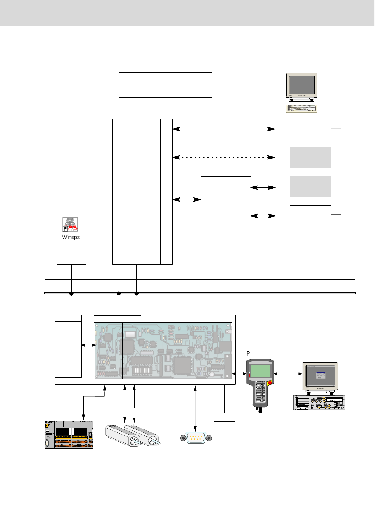
The following notes refer to point 3.1.2 Block structure of the rho4.0.
Via an external PC it is possible to communicate with the rho4.0 in Win-
dows via both a DDE server and DLL libraries. Various library functions
are available.
For the connection of the library functions the OEM has four parallel
channels available. The library functions are represented on Windows
side as DLL.
There is one common transmission channel available for ROPS4 and
DDE linking.
Electric Drives
and Controls
3−1Bosch Rexroth AGRhoMotion1070072367 / 04
Four Win channels are available in BAPS for communication with the
rho4.0 (Win_1 to Win_4). In addition, BAPS incorporates the capability
of creating one or more BAPS clients using library functions.
Coupling to a PCLrho4.0 (PC-programmable logic control), which may
run on the same computer, is provided through an internal TCP/IP connection. A data channel to the PCL is provided in the same way. The PCL
is programmed using the WIN-SPS software.
The rho4.0 provides three serial channels.
The PHG2000 is the default operating device for the rho4.0. In addition
to the default operating interface, it is possible to customise the interface
of the PHG2000 as desired using the BDT editor. Drivers and functions
are available for this purpose.
The rho4.0 incorporates a CAN interface to the digital drive amplifiers
(Bosch Servodyn D, Servodyn GC).
In addition, an interface for SERCOS drives is available.
A CAN interface is also used for the coupling of digital I/O. The
PCLrho4.0 gives the possibility of communicating by means of PROFIBUS-DP, CAN or INTERBUS-S by using a PCI field bus card.
ROPS4 can communicate with the rho4.0 via a TCP/IP or a serially connection.
BAPS plus uses the DDE Server4.
3−2 Electric Drives
Bosch Rexroth AG RhoMotion 1070072367 / 04
and Controls
Structure of the rho4.0
3.1.1 Outline structure
rho4.0
task management
file management
record preparation
interpolation
transformation
Windows
applications
Ethernet
TCP/IP
Standard-PC
Structure of the rho4.0
3.1.2 rho4.0 block diagramm
Electric Drives
and Controls
3−3Bosch Rexroth AGRhoMotion1070072367 / 04
External PC
WIN-PCL
Driver
V24/printer/power/
Hard disk/floppy/CD-ROM
Static link
ROPS4fkt.dll
ROPS4
Library
functions
D
Dyna-
L
mic
link
L
rho4fkt.dll
rho4
Library
functions
Dynamic link
Dynamic link
D
DDE-
L
Server
L
win.exe
D
ROPS4
L
Win.exe
L
D
L
L
D
D
D
E
OEM
Win.exe
(Switcher)
OEM
Win.exe
D
E
D
BAPS
D
plus
E
Driver
Driver
PCL
rho4.0
Driver
Ethernet
TCP/IP
T
C
P
/
I
P
C
A
N
Driver
I
nt
e
r
f
a
c
e
rho4.0
Real time core
Task administration
File administration
Record preparation
Interpolation
Transformation
S
E
R
C
O
C
A
N
Converter
rho4fkt.lib
rho4
Library
functions
PHG data
supply
Driver
V
2
4
PHG2000
BDT-editor
S
Floppy
I/O
Drives V24/20mA

3−4 Electric Drives
Structure of the rho4.0
Bosch Rexroth AG RhoMotion 1070072367 / 04
and Controls
3.1.3 Operating system of the rho4.0
The operating system is saved and secured against voltage loss on a
plug-in and an exchangeable compact flash disc (CF).
The change of a CF is only allowed when it is switched off by pulling the
rho4.0 component. The CF is internally mounted on the component for
safety reasons and can therefore not be removed from outside without
intention.
In the case of change of the operating system, after the exchange of the
CF, the previously saved machine parameters are to be loaded with
ROPS4 and the previously saved PCLrho4.0 program with WinSPS.
3.1.4 Floppy operation
PHG2000 display
As an option an external floppy drive can be connected to the control
rho4.0 as a storage medium supporting 3.5’ ’ disks with 1.44 MB and FAT.
The disks can be read or described from the control unit as well as from
Windows. On the disk, the file attribute may not be restricted, i.e. all files
have the attribute A(rchiv) allocated as default.
From the control side (real-time core), the operation is made via the
PHG2000.
As default the following display selection is activated:
D with the PHG mode 9.2 (list files), 9.3 (delete files), 9.4 (print files) and
9.9 (file attributes) one comes into the PHG2000 display ’Memory
management’.
D with the PHG mode 9.8 (floppy management) one comes into the
PHG2000 display ’Floppy management’.
Via an option byte (addr. 400062 = 1), it is possible to keep the display of
the modes 9.2, 9.3, 9.4, 9.9 in the PHG3 mode.
The operating mode ’File management’ gives the possibility of displaying up to 10 files of the user memory or the floppy disk at the same
time on the PHG2000 display.
The file names are limited to the format 8.3. Any extension with 3 signs is
allowed. Files that do not correspond to this format will be not displayed.
Directory structures of the floppy disk are not supported. All files that are
in the root directory of the floppy disk are displayed. Files are copied from
the control unit into the root directory of the floppy disk. Up to 224 files
can be filed into the root directory. An access to subdirectories is not possible.
Structure of the rho4.0
Electric Drives
and Controls
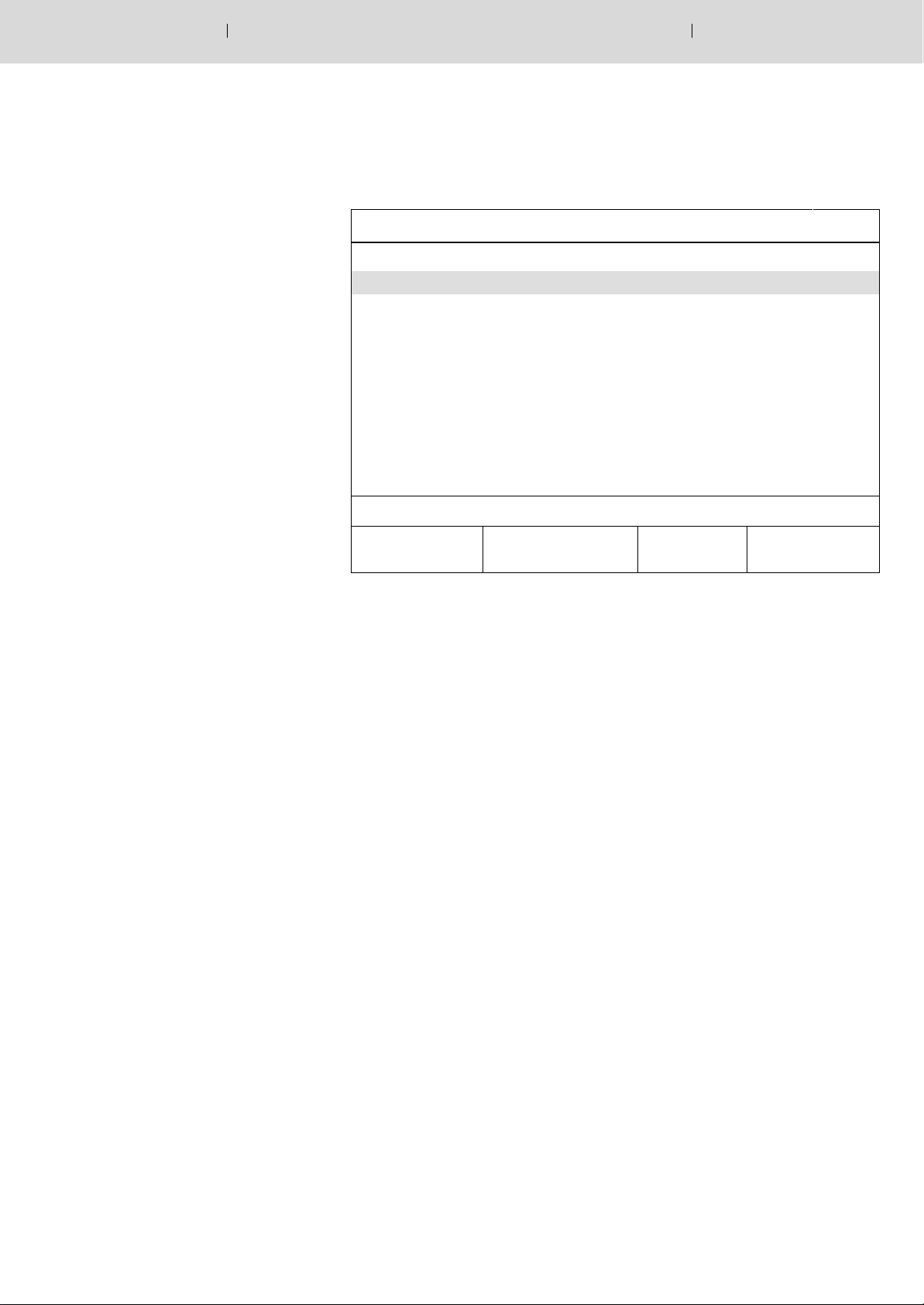
PHG2000-Display ’Memory management’
3−5Bosch Rexroth AGRhoMotion1070072367 / 04
The PHG2000 display ’Memory management’ is switched on with mode
9.2, 9.3, 9.4, 9.9.
Memory management
GrdStell.ird 1864331 20.09.00 10:06 RWD
GrdStell.pkt 64322 18.09.00 18:12 RWD
GrdStell.qll 4313 17.06.00 19:34 RWD
Palpos01.ird 64394 10.11.99 09:54 RWD
Palpos02.ird 84385 11.11.99 11:11 RWD
Palpos05.pkt 5376 05.09.00 17:09 RWD
Pal1 .pkt 5376 05.09.00 17:09 RWD
Pal2 .pkt 6357 08.11.00 13.08 RWD
Pal12 .pkt 12356 12.10.99 16.16 RWD
Pal22 .pkt 23466 04.05.98 15.43 RWD
MB total: 4.000 occupied: 3.052 free: 0.044
Delete
rho
Print
rho
Attributes
rho
Copy
rho −> FD
If the PHG2000 display ’Memory management’ is active, the uppermost
key row of the PHG2000 is used as function keys in the standard key assignment.
The following functions are started with it:
D ”Delete rho file“ (key code ’MOVE’)
D ”Print rho file’” (key code ’LINEAR’)
D ”Attributes rho file” (key code ’VIA’)
D ”Copy file from rho onto floppy” (key code ’TO’)
3−6 Electric Drives
Structure of the rho4.0
Bosch Rexroth AG RhoMotion 1070072367 / 04
and Controls
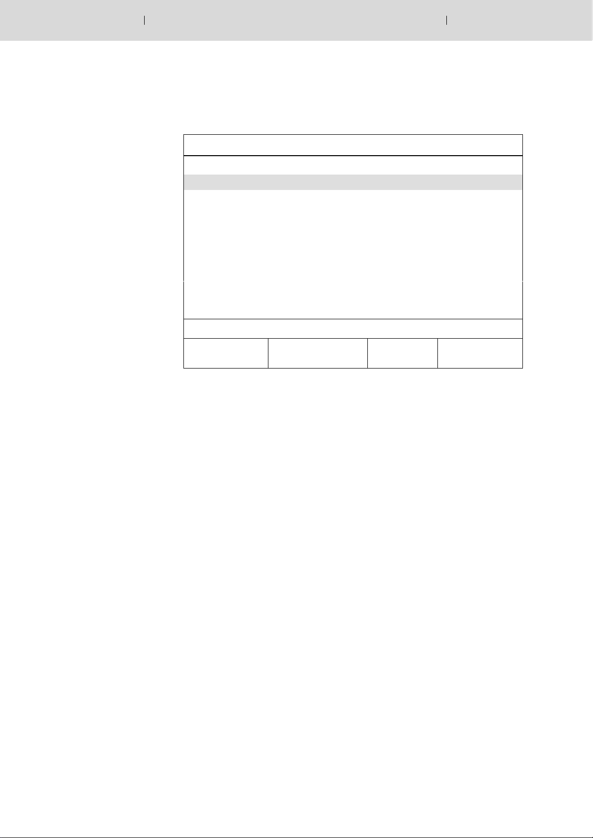
PHG2000-Display ’Floppy management’
With the PHG mode 9.8 (Floppy management) the following PHG2000
display is switched on:
GrdStel2.ird 2664331 20.09.00 10:06
GrdStel2.pkt 64322 18.09.00 18:12
GrdStel2.qll 4313 17.06.00 19:34
Palpos01.ird 64394 10.11.99 09:54
Palpos02.ird 84385 11.11.99 11:11
Palpos05.pkt 5376 05.09.00 17:09
Pal1 .pkt 5376 05.09.00 17:09
Pal2 .pkt 6357 08.11.00 13.08
Pal12 .pkt 12356 12.10.99 16.16
Pal22 .pkt 23466 04.05.98 15.43
Floppy management
MB total: 1.406 occupied: 1.354 free: 0.002
Delete
FD
Copy
MP −> FD
Copy
XMP −> FD
Copy
FD −> rho
If the PHG2000 display ’Floppy management’ is active, the uppermost
key row of the PHG2000 is used as function keys in the standard key assignment.
The following functions are started with it:
D ”Delete FD file” (key code ’MOVE’)
D ”Copy machine parameters from rho onto floppy” (key code ’LI-
NEAR’)
D ”Copy extended machine parameters from rho onto floppy”) (key
code ’VIA’)
D ”Copy files from floppy onto rho”) (key code ’TO’)
Structure of the rho4.0
Electric Drives
and Controls
Key assignment for selection
3−7Bosch Rexroth AGRhoMotion1070072367 / 04
The following key combinations correspond to the cursor movements
within the file list of the display:
Standard keyboard assignment
<up arrowl> : move cursor up <Shift> <5>
<down arrow> : move cursor down <Shift> < . >
< ’<’ > : move cursor up by a page <Alt> <7>
< ’>’ > : move cursor down by a page <Alt> <8>
<BEGIN> : position cursor at the beginning
<BEGIN>
of the file list
<END> : position cursor at the end of the
<END>
file list
<’[’> : set mark (beginning of an area) <Alt> <WENN>
<WDH> : Update display (Refresh list) <WDH>
<left arrow> : Quit operating mode
<Shift> <1>
file management
The inversely represented file(s) is/are selected for the function key to be
confirmed. Any large, coherent area over several pages can be selected. The processing of a selected area (file list) is interrupted with <left
arrow>.
CAUTION
The disk may not be removed from the drive during a write access.
It can destroy (logically) the disk.
3−8 Electric Drives
Structure of the rho4.0
Bosch Rexroth AG RhoMotion 1070072367 / 04
and Controls
3.2 Digital I/O
On the rho4.0, (without additionally possible coupling of decentral I/O
modules) 16 digital inputs and 8 digital outputs are available.
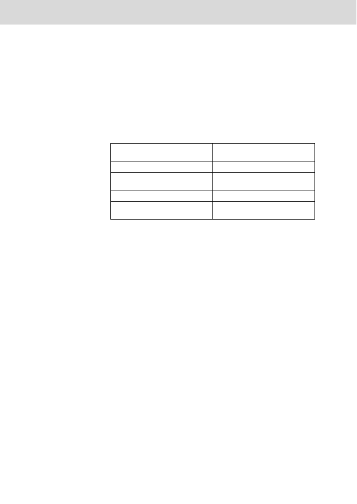
3.2.1 Digital inputs
The digital inputs of the rho4.0 are multi-function inputs. They can be
used alternatively for several control functions:
Multifunction type can be addressed via channel
High-speed constant start 611 to 618
number
High-speed constant start
High-speed inputs in the BAPS program
High-speed asynchronous inputs 1801 to 1816
Processing of the inputs in the
PCLrho4.0 program
801 to 816
−−−
For certain applications, it is necessary to trigger a movement as Highspeed as possible and always with as constant idle time as possible on a
condition.
By means of the “WAIT UNTIL ...” instruction − by using the input channel
numbers 611 to 618 it is possible to start high-speedly and with constant
delay time (with quantization of an interpolation cycle P5) on a condition.
A movement is triggered as High-speed as possible through a condition
when the BAPS program contains the following instructione sequence:
WAIT UNTIL bedingung_erfuellt MOVE kin1 LINEAR TO P1
kin1: Name of the kinematic that is moved afterward
Condition_met: e.g. SL_INP_1=1
SL_INP_2=0
Any waiting time can be programmed before the next movement is executed:
.
.
1) WAIT UNTIL SL_INP_1=1 MAX_TIME=0.15
2) MOVE DEST_POS
.
.
 Loading...