

Bosch REXROTH IndraDrive, REXROTH IndraMotion MLD Applications Manual
Electric Drives
LSA Control S.L. www.lsa-control.com comercial@lsa-control.com (+34) 960 62 43 01
and Controls Pneumatics
Hydraulics
Linear Motion and
Assembly Technologies
Service
Bosch Rexroth AG DOK-INDRV*-MLD-APPLI**-AW02-EN-P
LSA Control S.L. www.lsa-control.com comercial@lsa-control.com (+34) 960 62 43 01
Rexroth IndraDrive Rexroth IndraMotion MLD Application Examples
Title
Type of Documentation
Document Typecode
Internal File Reference
Purpose of Documentation
Record of Revision
Copyright
Validity
Published by
Note
Rexroth IndraDrive
Rexroth IndraMotion MLD
Application Examples
Application Manual
DOK-INDRV*-MLD-APPLI**-AW02-EN-P
RS-5bed5147cc1fce5f0a6846a00169d1a1-1-en-US-3
By means
of four application examples, this documentation shows an intro‐
duction to the programming of the drive-integrated PLC (IndraMotion MLD).
Edition
DOK-INDRV*-MLD-APPLI**-AW01-EN-P 09/2008 First edition
DOK-INDRV*-MLD-APPLI**-AW02-EN-P 07/2010 Edition 02
Release Date Notes
© Bosch Rexroth AG 2010
Copying this
document, giving it to others and the use or communication of the
contents thereof without express authority, are forbidden. Offenders are liable
for the payment of damages. All rights are reserved in the event of the grant of
a patent or the registration of a utility model or design (DIN 34-1).
The specified data is for product description purposes only and may not be
deemed to be guaranteed unless expressly confirmed in the contract. All rights
are reserved with respect to the content of this documentation and the availa‐
bility of the product.
Bosch Rexroth AG
Bgm.-Dr.-Nebel-Str. 2 ■ D-97816 Lohr a. Main
Telephone +49 (0)93 52/ 40-0 ■ Fax +49 (0)93 52/ 40-48 85
http://www.boschrexroth.com/
Dept. DC-IA/EDY
This document has been printed on chlorine-free bleached paper.

DOK-INDRV*-MLD-APPLI**-AW02-EN-P
LSA Control S.L. www.lsa-control.com comercial@lsa-control.com (+34) 960 62 43 01
Rexroth IndraDrive Rexroth IndraMotion MLD Application Examples
Bosch Rexroth AG I/97
Table of Contents
Table of Contents
Page
1 Introduction.................................................................................................................... 3
1.1
1.2 Reference Documentations.................................................................................................................... 3
1.2.1 IndraMotion MLD................................................................................................................................. 3
1.2.2 Firmware.............................................................................................................................................. 4
1.2.3 Drive System....................................................................................................................................... 4
2 Important Directions for Use ......................................................................................... 5
2.1 Appropriate Use ..................................................................................................................................... 5
2.1.1 Introduction.......................................................................................................................................... 5
2.1.2 Areas of Use and Application.............................................................................................................. 5
2.2 Inappropriate Use................................................................................................................................... 6
About This Documentation..................................................................................................................... 3
3 Safety Instructions for Electric Drives and Controls ...................................................... 7
3.1 Definitions of Terms................................................................................................................................ 7
3.2 General Information................................................................................................................................ 8
3.2.1 Using the Safety Instructions and Passing Them on to Others........................................................... 8
3.2.2 Requirements for Safe Use................................................................................................................. 8
3.2.3 Hazards by Improper Use.................................................................................................................... 9
3.3 Instructions with Regard to Specific Dangers....................................................................................... 10
3.3.1 Protection Against Contact with Electrical Parts and Housings......................................................... 10
3.3.2 Protective Extra-Low Voltage as Protection Against Electric Shock ................................................ 11
3.3.3 Protection Against Dangerous Movements....................................................................................... 11
3.3.4 Protection Against Magnetic and Electromagnetic Fields During Operation and Mounting.............. 13
3.3.5 Protection Against Contact With Hot Parts........................................................................................ 13
3.3.6 Protection During Handling and Mounting......................................................................................... 13
3.3.7 Battery Safety.................................................................................................................................... 14
3.3.8 Protection Against Pressurized Systems........................................................................................... 14
3.4 Explanation of Signal Words and the Safety Alert Symbol................................................................... 15
4 Requirements............................................................................................................... 17
4.1 Firmware and Hardware Requirements................................................................................................ 17
4.2 Enabling of Functional Packages......................................................................................................... 17
4.3 Programming........................................................................................................................................ 18
5 Double-Axis Positioning Control (Pick and Place)....................................................... 21
5.1 Task Definition – Application Description.............................................................................................. 21
5.1.1 General Information........................................................................................................................... 21
5.1.2 Mechanical Configuration.................................................................................................................. 21
5.1.3 Sequence of Motion........................................................................................................................... 22
5.2 Programming........................................................................................................................................ 28
5.3 Commissioning and Testing................................................................................................................. 33
5.4 Visualization and Diagnostics............................................................................................................... 33

II/97
LSA Control S.L. www.lsa-control.com comercial@lsa-control.com (+34) 960 62 43 01
Table of Contents
Bosch Rexroth AG DOK-INDRV*-MLD-APPLI**-AW02-EN-P
Rexroth IndraDrive Rexroth IndraMotion MLD Application Examples
Page
6 Intelligent Error Reaction............................................................................................. 35
6.1 Task Definition - Application Description.............................................................................................. 35
6.2 Parameterizing/Configuring the Drive................................................................................................... 39
6.3 Programming........................................................................................................................................ 44
6.4 Commissioning and Testing................................................................................................................. 47
6.5 Visualization and Diagnostics............................................................................................................... 47
7 Synchronous Multi-Axis Motion With Virtual Master Axis............................................ 51
7.1 Task Definition – Application Description.............................................................................................. 51
7.1.1 General Information........................................................................................................................... 51
7.1.2 Sequence of Motion........................................................................................................................... 51
7.2 Parameterizing/Configuring the Drive................................................................................................... 53
7.2.1 Overview............................................................................................................................................ 53
7.2.2 CCD Master Axis............................................................................................................................... 54
7.2.3 CCD Slave Axis................................................................................................................................. 61
7.3 Programming........................................................................................................................................ 64
7.4 Commissioning and Testing................................................................................................................. 70
7.5 Notes on Programming and Parameterization for Other Relevant Types of Master Axis Linking........ 71
7.5.1 General Information........................................................................................................................... 71
7.5.2 Real Axis in CCD Slave Moves Synchronously to Real Axis in CCD Master.................................... 72
7.5.3 Real Axis in CCD Master and CCD Slave Move Synchronously to Measuring Encoder Position in CCD
Slave.................................................................................................................................................. 73
7.5.4 Position Command Value Linking (Gantry Axis)................................................................................ 75
8 Vibration Damping With Superimposed Process Loop (Process Control With Intelligent
Servo Axis)................................................................................................................... 77
8.1 Task Definition – Application Description.............................................................................................. 77
8.1.1 Task Definition................................................................................................................................... 77
8.1.2 Functional Overview/Concept............................................................................................................ 77
8.2 Requirements/Settings......................................................................................................................... 78
8.3 Programming........................................................................................................................................ 82
8.3.1 System Structure............................................................................................................................... 82
8.3.2 Funktion Block "MX_PID_Regler"...................................................................................................... 83
8.3.3 Accessing Drive Parameters............................................................................................................. 85
8.3.4 Generating the Command Value Characteristic................................................................................ 86
8.3.5 Overall Structure of Process Control................................................................................................. 87
8.3.6 Visualization and Diagnostics............................................................................................................ 88
8.4 Commissioning and Testing................................................................................................................. 88
8.5 Visualization and Diagnostics............................................................................................................... 90
9 Service and Support.................................................................................................... 93
Index............................................................................................................................ 95
DOK-INDRV*-MLD-APPLI**-AW02-EN-P
LSA Control S.L. www.lsa-control.com comercial@lsa-control.com (+34) 960 62 43 01
Rexroth IndraDrive Rexroth IndraMotion MLD Application Examples
1 Introduction
1.1 About This Documentation
Purpose of Documentation
means of four application examples, this documentation shows an intro‐
By
duction to the programming of the drive-integrated PLC (IndraMotion MLD). It
demonstrates various problems occurring in the production process which are
resolved with IndraMotion MLD.
The following examples of application are introduced and implemented as MLD
solutions:
● Double-axis positioning control (Pick and Place)
● Intelligent error reaction
● Synchronous multi-axis motion with virtual master axis
● Vibration damping with superimposed process loop
Bosch Rexroth AG 3/97
Introduction
In a simple way, the program examples demonstrate how to realize the follow‐
ing topics:
● Reading and writing drive parameters
● Reading digital and analog inputs
● Setting digital outputs
● Implementing a process control
● Motion Control: (Positioning and axis-synchronous motion)
● Programming an internal error reaction
1.2 Reference Documentations
1.2.1 IndraMotion MLD
Title Type of documentation
Rexroth IndraMotion MLD Application Manual DOK-INDRV*-MLD-**VRS**-
Rexroth IndraMotion MLD Library Library Description DOK-INDRV*-MLD-SYSLIB*-
Rexroth IndraMotion MLD Getting
Started
1) In the document typecodes, "xx" is a wild card for the current edition of
Fig.1-1: Documentations – Overview
Summary DOK-IM*MLD*-F*STEP**V**-
the documentation
Manual);
Document typecode
AWxx-EN-P
FKxx-EN-P
KB01-EN-P
(example: AW03 is the third edition of an Application
1)
Part number
R911306084
R911309224
R911319306

4/97
LSA Control S.L. www.lsa-control.com comercial@lsa-control.com (+34) 960 62 43 01
Bosch Rexroth AG DOK-INDRV*-MLD-APPLI**-AW02-EN-P
Introduction
1.2.2 Firmware
Rexroth IndraDrive Rexroth IndraMotion MLD Application Examples
Title
Rexroth IndraDrive …
Rexroth IndraDrive
Firmware for Drive Controllers
1.2.3 Drive System
Title
Rexroth IndraDrive
Rexroth IndraDrive
Drive Controllers Control Sections
Type of documentation
Functional Description DOK-INDRV*-MP*-05VRS**-
1) In the document typecodes, "xx" is a wild card for the current edition of
the documentation
Description);
Document typecode
FKxx-EN-P
(example: FK02 is the second edition of a Functional
1)
Part number
R911320182
Fig.1-2: Documentations – Overview
Type of documentation
Project Planning Manual DOK-INDRV*-CSH********-PRxx-
1) In the document typecodes, "xx" is a wild card for the current edition of
the documentation
ning Manual);
Document typecode
EN-P
(example: PR01 is the first edition of a Project Plan‐
1)
Part number
R911295012
Fig.1-3: Documentations – Overview
DOK-INDRV*-MLD-APPLI**-AW02-EN-P
LSA Control S.L. www.lsa-control.com comercial@lsa-control.com (+34) 960 62 43 01
Rexroth IndraDrive Rexroth IndraMotion MLD Application Examples
2 Important Directions for Use
2.1 Appropriate Use
Bosch Rexroth AG 5/97
Important Directions for Use
2.1.1
Introduction
Rexroth products represent state-of-the-art developments and manufacturing.
They are tested prior to delivery to ensure operating safety and reliability.
WARNING
The products have been designed for use in the industrial environment and may
only be
situations resulting in property damage and personal injury can occur.
Before using Rexroth products,
propriate use of the products are satisfied:
● Personnel that in any way, shape or form uses our products must first read
● If the products take the form of hardware, then they must remain in their
● Do not mount damaged or faulty products or use them in operation.
● Make sure that the products have been installed in the manner described
used in the appropriate way. If they are not used in the appropriate way,
Rexroth as manufacturer is not liable for any damages resulting
inappropriate use. In such cases, the guarantee and the right
from
to payment of damages resulting from inappropriate use are forfei‐
ted. The user alone carries all responsibility of the risks.
and understand the relevant safety instructions and be familiar with ap‐
propriate use.
original state, in other words, no structural changes are permitted. It is not
permitted to decompile software products or alter source codes.
in the relevant documentation.
Personal injury and property damage caused
by incorrect use of the products!
make sure that all the pre-requisites for an ap‐
2.1.2 Areas of Use and Application
Drive controllers made by Rexroth are designed to control electrical motors and
monitor their operation.
Control and monitoring of the Drive controllers may require additional sensors
and actors.
The drive controllers may only be used with the accessories and
parts specified
specifically named, then it may neither be mounted nor connected.
The same applies to cables and lines.
Operation is only permitted in the specified configurations and com‐
binations of components using the software and firmware as speci‐
fied in the relevant Functional Descriptions.
Drive controllers have to be programmed before commissioning, making it pos‐
sible for the motor to execute the specific functions of an application.
Drive controllers
single- and multi-axis drive and control tasks.
To ensure application-specific use of Drive controllers, device types of different
drive power and different interfaces are available.
of the Rexroth IndraDrive line have been developed for use in
in this documentation. If a component has not been
6/97
LSA Control S.L. www.lsa-control.com comercial@lsa-control.com (+34) 960 62 43 01
Important Directions for Use
Bosch Rexroth AG DOK-INDRV*-MLD-APPLI**-AW02-EN-P
Typical applications include, for example:
● Handling and mounting systems,
●
Packaging and food machines,
● Printing and paper processing machines and
● Machine tools.
Drive controllers may only be operated under the assembly and installation
conditions described in this documentation, in the specified position of normal
use and under the ambient conditions as described (temperature, degree of
protection, humidity, EMC, etc.).
2.2 Inappropriate Use
Using the Drive controllers outside of the operating conditions described in this
documentation and outside of the indicated technical data and specifications is
defined as "inappropriate use".
Drive controllers must not be used, if ...
● they are subject to operating conditions that do not meet the specified
ambient conditions. This includes, for example, operation under water,
under extreme temperature fluctuations or extremely high maximum tem‐
peratures.
● Furthermore, Drive controllers must not be used in applications which
have not been expressly authorized by Rexroth. Please carefully follow
the specifications outlined in the general Safety Instructions!
Rexroth IndraDrive Rexroth IndraMotion MLD Application Examples
Components of the drive system Rexroth IndraDrive are products
of category
IEC 61800‑3. These components are not provided for use in a public
low-voltage mains supplying residential areas. If these components
are used in such a mains, high-frequency interference is to be ex‐
pected. This can require additional measures of radio interference
suppression.
C3 (with restricted distribution) according to

DOK-INDRV*-MLD-APPLI**-AW02-EN-P
LSA Control S.L. www.lsa-control.com comercial@lsa-control.com (+34) 960 62 43 01
Rexroth IndraDrive Rexroth IndraMotion MLD Application Examples
Bosch Rexroth AG 7/97
Safety Instructions for Electric Drives and Controls
3 Safety Instructions for Electric Drives and Controls
3.1 Definitions of Terms
Application Documentation
Component
Control System
Device
Electrical Equipment
Electric Drive System
Installation
Machine
Manufacturer
Product
Project Planning Manual
Qualified Persons
Application
the user of the product about the use and safety-relevant features for config‐
uring, integrating, installing, mounting, commissioning, operating, maintaining,
repairing and decommissioning the product. The following terms are also used
for this kind of documentation: User Guide, Operation Manual, Commissioning
Manual, Instruction Manual, Project Planning Manual, Application Manual, etc.
A component is a combination of elements with a specified function, which are
part of a piece of equipment, device or system. Components of the electric drive
and control system are, for example, supply units, drive controllers, mains
choke, mains filter, motors, cables, etc.
A control system comprises several interconnected control components placed
on the market as a single functional unit.
A device is a finished product with a defined function, intended for users and
placed on the market as an individual piece of merchandise.
Electrical equipment encompasses all devices used to generate, convert, trans‐
mit, distribute or apply electrical energy, such as electric motors, transformers,
switching devices, cables, lines, power-consuming devices, circuit board as‐
semblies, plug-in units, control cabinets, etc.
An electric drive system comprises all components from mains supply to motor
shaft; this includes, for example, electric motor(s), motor encoder(s), supply
units and drive controllers, as well as auxiliary and additional components, such
as mains filter, mains choke and the corresponding lines and cables.
An installation consists of several devices or systems interconnected for a de‐
fined purpose and on a defined site which, however, are not intended to be
placed on the market as a single functional unit.
A machine is the entirety of interconnected parts or units at least one of which
is movable. Thus, a machine consists of the appropriate machine drive ele‐
ments, as well as control and power circuits, which have been assembled for
a specific application. A machine is, for example, intended for processing,
treatment, movement or packaging of a material. The term "machine" also cov‐
ers a combination of machines which are arranged and controlled in such a way
that they function as a unified whole.
The manufacturer is an individual or legal entity bearing responsibility for the
design and manufacture of a product which is placed on the market in the in‐
dividual's or legal entity's name. The manufacturer can use finished products,
finished parts or finished elements, or contract out work to subcontractors.
However, the manufacturer must always have overall control and possess the
required authority to take responsibility for the product.
Examples of a product: Device, component, part, system, software, firmware,
among other things.
A project planning manual is part of the application documentation used to
support the sizing and planning of systems, machines or installations.
In terms of this application documentation, qualified persons are those persons
who are familiar with the installation, mounting, commissioning and operation
of the components of the electric drive and control system, as well as with the
hazards this implies, and who possess the qualifications their work requires. To
comply with these qualifications, it is necessary, among other things,
documentation comprises the entire documentation used to inform

8/97
LSA Control S.L. www.lsa-control.com comercial@lsa-control.com (+34) 960 62 43 01
Safety Instructions for Electric Drives and Controls
Bosch Rexroth AG DOK-INDRV*-MLD-APPLI**-AW02-EN-P
Rexroth IndraDrive Rexroth IndraMotion MLD Application Examples
1) to be trained, instructed or authorized to switch electric circuits and devices
safely on and off, to ground them and to mark them
2) to be trained or instructed to maintain and use adequate safety equipment
3) to attend a course of instruction in first aid
User
A user
placed on the market.
is a person installing, commissioning or using a product which has been
3.2 General Information
3.2.1 Using the Safety Instructions and Passing Them on to Others
Do not attempt to install and operate the components of the electric drive and
control system without first reading all documentation provided with the product.
Read and understand these safety instructions and all user documentation prior
to working with these components. If you do not have the user documentation
for the components, contact your responsible Rexroth sales partner. Ask for
these documents to be sent immediately to the person or persons responsible
for the safe operation of the components.
If the component is resold, rented and/or passed on to others in any other form,
these safety instructions must be delivered with the component in the official
language of the user's country.
Improper use of these components, failure to follow the safety instructions in
this document or tampering with the product, including disabling of safety de‐
vices, could result in property damage, injury, electric shock or even death.
3.2.2 Requirements for Safe Use
Read the following instructions before initial commissioning of the components
of the electric drive and control system in order to eliminate the risk of injury
and/or property damage. You must follow these safety instructions.
● Rexroth is not liable for damages resulting from failure to observe the
safety instructions.
● Read the operating, maintenance and safety instructions in your language
before commissioning. If you find that you cannot completely understand
the application documentation in the available language, please ask your
supplier to clarify.
● Proper and correct transport, storage, mounting and installation, as well
as care in operation and maintenance, are prerequisites for optimal and
safe operation of the component.
● Only qualified persons may work with components of the electric drive and
control system or within its proximity.
● Only use accessories and spare parts approved by Rexroth.
● Follow the safety regulations and requirements of the country in which the
components of the electric drive and control system are operated.
● Only use the components of the electric drive and control system in the
manner that is defined as appropriate. See chapter "Appropriate Use".
● The ambient and operating conditions given in the available application
documentation must be observed.
● Applications for functional safety are only allowed if clearly and explicitly
specified in the application documentation "Integrated Safety Technolo‐
gy". If this is not the case, they are excluded. Functional safety is a safety

DOK-INDRV*-MLD-APPLI**-AW02-EN-P
LSA Control S.L. www.lsa-control.com comercial@lsa-control.com (+34) 960 62 43 01
Rexroth IndraDrive Rexroth IndraMotion MLD Application Examples
concept in which measures of risk reduction for personal safety depend
on electrical, electronic or programmable control systems.
● The information
use of the delivered components contains only examples of applications
and suggestions.
The machine and installation manufacturers must
– make sure that the delivered components are suited for their individ‐
ual application and check the information given in this application
documentation with regard to the use of the components,
– make sure that their individual application complies with the appli‐
cable safety regulations and standards and carry out the required
measures, modifications and complements.
● Commissioning of the delivered components is only allowed once it is sure
that the machine or installation in which the components are installed
complies with the national regulations, safety specifications and standards
of the application.
● Operation is only allowed if the national EMC regulations for the applica‐
tion are met.
● The instructions for installation in accordance with EMC requirements can
be found in the section on EMC in the respective application documenta‐
tion.
The machine or installation manufacturer is responsible for compliance
with the limit values as prescribed in the national regulations.
● The technical data, connection and installation conditions of the compo‐
nents are specified in the respective application documentations and must
be followed at all times.
given in the application documentation with regard to the
National regulations which the user must take into account
● European countries: In accordance with European EN standards
● United States of America (USA):
– National Electrical Code (NEC)
– National Electrical Manufacturers Association (NEMA), as well as
local engineering regulations
– Regulations of the National Fire Protection Association (NFPA)
● Canada: Canadian Standards Association (CSA)
● Other countries:
– International Organization for Standardization (ISO)
– International Electrotechnical Commission (IEC)
Bosch Rexroth AG 9/97
Safety Instructions for Electric Drives and Controls
3.2.3 Hazards by Improper Use
● High electrical voltage and high working current! Danger to life or serious
injury by electric shock!
● High electrical voltage by incorrect connection! Danger to life or injury by
electric shock!
● Dangerous movements! Danger to life, serious injury or property damage
by unintended motor movements!
● Health hazard for persons with heart pacemakers, metal implants and
hearing aids in proximity to electric drive systems!
● Risk of burns by hot housing surfaces!

10/97
LSA Control S.L. www.lsa-control.com comercial@lsa-control.com (+34) 960 62 43 01
Safety Instructions for Electric Drives and Controls
Bosch Rexroth AG DOK-INDRV*-MLD-APPLI**-AW02-EN-P
Rexroth IndraDrive Rexroth IndraMotion MLD Application Examples
● Risk of injury by improper handling! Injury by crushing, shearing, cutting,
hitting!
●
Risk of injury by improper handling of batteries!
● Risk of injury by improper handling of pressurized lines!
3.3 Instructions with Regard to Specific Dangers
3.3.1 Protection Against Contact with Electrical Parts and Housings
This section concerns components of the electric drive and control
system with voltages of more than 50 volts.
Contact with parts conducting voltages above 50 volts can cause personal
danger and
and control system, it is unavoidable that some parts of these components
conduct dangerous voltage.
High electrical voltage! Danger to life, risk of injury by electric shock or serious
injury!
● Only qualified persons are allowed to operate, maintain and/or repair the
components of the electric drive and control system.
● Follow the general installation and safety regulations when working on
power installations.
● Before switching on, the equipment grounding conductor must have been
permanently connected to all electric components in accordance with the
connection diagram.
● Even for brief measurements or tests, operation is only allowed if the
equipment grounding conductor has been permanently connected to the
points of the components provided for this purpose.
● Before accessing electrical parts with voltage potentials higher than 50 V,
you must disconnect electric components from the mains or from the pow‐
er supply unit. Secure the electric component from reconnection.
● With electric components, observe the following aspects:
Always wait 30 minutes after switching off power to allow live capacitors
to discharge before accessing an electric component. Measure the elec‐
trical voltage of live parts before beginning to work to make sure that the
equipment is safe to touch.
● Install the covers and guards provided for this purpose before switching
on.
● Never touch electrical connection points of the components while power
is turned on.
● Do not remove or plug in connectors when the component has been pow‐
ered.
● Under specific conditions, electric drive systems can be operated at mains
protected by residual-current-operated circuit-breakers sensitive to uni‐
versal current (RCDs/RCMs).
● Secure built-in devices from penetrating foreign objects and water, as well
as from direct contact, by providing an external housing, for example a
control cabinet.
electric shock. When operating components of the electric drive

DOK-INDRV*-MLD-APPLI**-AW02-EN-P
LSA Control S.L. www.lsa-control.com comercial@lsa-control.com (+34) 960 62 43 01
Rexroth IndraDrive Rexroth IndraMotion MLD Application Examples
High housing voltage and high leakage current! Danger to life, risk of injury by
electric shock!
● Before switching
components of the electric drive and control system to the equipment
grounding conductor at the grounding points.
● Connect the equipment grounding conductor of the components of the
electric drive and control system permanently to the main power supply at
all times. The leakage current is greater than 3.5 mA.
● Establish an equipment grounding connection with a copper wire of a
cross section of at least 10 mm2 (8 AWG) or additionally run a second
equipment grounding conductor of the same cross section as the original
equipment grounding conductor.
on and before commissioning, ground or connect the
Safety Instructions for Electric Drives and Controls
Bosch Rexroth AG 11/97
3.3.2 Protective Extra-Low Voltage as Protection Against Electric Shock
Protective extra-low voltage is used to allow connecting devices with basic in‐
sulation to extra-low voltage circuits.
On components of an electric drive and control system provided by Rexroth, all
connections and terminals with voltages between 5 and 50 volts are PELV
("Protective Extra-Low Voltage") systems. It is allowed to connect devices
equipped with basic insulation (such as programming devices, PCs, notebooks,
display units) to these connections.
Danger to life, risk of injury by electric shock! High electrical voltage by incorrect
connection!
If extra-low voltage circuits of devices containing voltages and circuits of more
than 50 volts (e.g., the mains connection) are connected to Rexroth products,
the connected extra-low voltage circuits must comply with the requirements for
PELV ("Protective Extra-Low Voltage").
3.3.3 Protection Against Dangerous Movements
Dangerous movements can be caused by faulty control of connected motors.
Some common examples are:
● Improper or wrong wiring or cable connection
● Operator errors
● Wrong input of parameters before commissioning
● Malfunction of sensors and encoders
● Defective components
● Software or firmware errors
These errors can occur immediately after equipment is switched on or even
after an unspecified time of trouble-free operation.
The monitoring functions in the components of the electric drive and control
system will normally be sufficient to avoid malfunction in the connected drives.
Regarding personal safety, especially the danger of injury and/or property dam‐
age, this alone cannot be relied upon to ensure complete safety. Until the
integrated monitoring functions become effective, it must be assumed in any
case that faulty drive movements will occur. The extent of faulty drive move‐
ments depends upon the type of control and the state of operation.

12/97
LSA Control S.L. www.lsa-control.com comercial@lsa-control.com (+34) 960 62 43 01
Bosch Rexroth AG DOK-INDRV*-MLD-APPLI**-AW02-EN-P
Safety Instructions for Electric Drives and Controls
Dangerous movements! Danger to life, risk of injury, serious injury or property
damage!
A risk assessment
specific conditions, in which the components of the electric drive and control
system are installed.
As a result of the risk assessment, the user must provide for monitoring func‐
tions and higher-level measures on the installation side for personal safety. The
safety regulations applicable to the installation or machine must be taken into
consideration. Unintended machine movements or other malfunctions are pos‐
sible if safety devices are disabled, bypassed or not activated.
To avoid accidents, injury and/or property damage:
● Keep free and clear of the machine’s range of motion and moving machine
parts. Prevent personnel from accidentally entering the machine’s range
of motion by using, for example:
– Safety fences
– Safety guards
– Protective coverings
– Light barriers
● Make sure the safety fences and protective coverings are strong enough
to resist maximum possible kinetic energy.
● Mount emergency stopping switches in the immediate reach of the oper‐
ator. Before commissioning, verify that the emergency stopping equip‐
ment works. Do not operate the machine if the emergency stopping switch
is not working.
● Prevent unintended start-up. Isolate the drive power connection by means
of OFF switches/OFF buttons or use a safe starting lockout.
● Make sure that the drives are brought to safe standstill before accessing
or entering the danger zone.
● Additionally secure vertical axes against falling or dropping after switching
off the motor power by, for example,
– mechanically securing the vertical axes,
– adding an external braking/arrester/clamping mechanism or
– ensuring sufficient counterbalancing of the vertical axes.
● The standard equipment motor holding brake or an external holding brake
controlled by the drive controller is not sufficient to guarantee personal
safety!
● Disconnect electrical power to the components of the electric drive and
control system using the master switch and secure them from reconnec‐
tion ("lock out") for:
– Maintenance and repair work
– Cleaning of equipment
– Long periods of discontinued equipment use
● Prevent the operation of high-frequency, remote control and radio equip‐
ment near components of the electric drive and control system and their
supply leads. If the use of these devices cannot be avoided, check the
machine or installation, at initial commissioning of the electric drive and
control system, for possible malfunctions when operating such high-fre‐
quency, remote control and radio equipment in its possible positions of
normal use. It might possibly be necessary to perform a special electro‐
magnetic compatibility (EMC) test.
Rexroth IndraDrive Rexroth IndraMotion MLD Application Examples
must be prepared for the installation or machine, with its

DOK-INDRV*-MLD-APPLI**-AW02-EN-P
LSA Control S.L. www.lsa-control.com comercial@lsa-control.com (+34) 960 62 43 01
Rexroth IndraDrive Rexroth IndraMotion MLD Application Examples
Safety Instructions for Electric Drives and Controls
Bosch Rexroth AG 13/97
3.3.4 Protection Against Magnetic and Electromagnetic Fields During Oper‐
ation and Mounting
Magnetic
or permanent magnets of electric motors represent a serious danger to persons
with heart pacemakers, metal implants and hearing aids.
Health hazard for persons with heart pacemakers, metal implants and hearing
aids in proximity to electric components!
● Persons with heart pacemakers and metal implants are not allowed to
● If it is necessary for somebody with a heart pacemaker to enter such an
● Those with metal implants or metal pieces, as well as with hearing aids,
and electromagnetic fields generated by current-carrying conductors
enter the following areas:
– Areas in which components of the electric drive and control systems
are mounted, commissioned and operated.
– Areas in which parts of motors with permanent magnets are stored,
repaired or mounted.
area, a doctor must be consulted prior to doing so. The noise immunity of
implanted heart pacemakers differs so greatly that no general rules can
be given.
must consult a doctor before they enter the areas described above.
3.3.5 Protection Against Contact With Hot Parts
Hot surfaces of components of the electric drive and control system. Risk of
burns!
● Do not touch hot surfaces of, for example, braking resistors, heat sinks,
supply units and drive controllers, motors, windings and laminated cores!
● According to the operating conditions, temperatures of the surfaces can
be higher than 60 °C (140 °F) during or after operation.
● Before touching motors after having switched them off, let them cool down
for a sufficient period of time. Cooling down can require up to 140 mi‐
nutes! The time required for cooling down is approximately five times the
thermal time constant specified in the technical data.
● After switching chokes, supply units and drive controllers off, wait 15 mi‐
nutes to allow them to cool down before touching them.
● Wear safety gloves or do not work at hot surfaces.
● For certain applications, and in accordance with the respective safety reg‐
ulations, the manufacturer of the machine or installation must take meas‐
ures to avoid injuries caused by burns in the final application. These
measures can be, for example: Warnings at the machine or installation,
guards (shieldings or barriers) or safety instructions in the application
documentation.
3.3.6 Protection During Handling and Mounting
Risk of injury by improper handling! Injury by crushing, shearing, cutting, hitting!
● Observe the relevant statutory regulations of accident prevention.
● Use suitable equipment for mounting and transport.
● Avoid jamming and crushing by appropriate measures.
14/97
LSA Control S.L. www.lsa-control.com comercial@lsa-control.com (+34) 960 62 43 01
Safety Instructions for Electric Drives and Controls
Bosch Rexroth AG DOK-INDRV*-MLD-APPLI**-AW02-EN-P
● Always use suitable tools. Use special tools if specified.
● Use lifting equipment and tools in the correct manner.
●
Use suitable protective equipment (hard hat, safety goggles, safety shoes,
safety gloves, for example).
● Do not stand under hanging loads.
● Immediately clean up any spilled liquids from the floor due to the risk of
slipping.
3.3.7 Battery Safety
Batteries consist of active chemicals in a solid housing. Therefore, improper
handling can cause injury or property damage.
Risk of injury by improper handling!
● Do not attempt to reactivate low batteries by heating or other methods (risk
of explosion and cauterization).
● Do not attempt to recharge the batteries as this may cause leakage or
explosion.
● Do not throw batteries into open flames.
● Do not dismantle batteries.
● When replacing the battery/batteries, do not damage the electrical parts
installed in the devices.
● Only use the battery types specified for the product.
Rexroth IndraDrive Rexroth IndraMotion MLD Application Examples
Environmental protection and disposal! The batteries contained in
the product
sea transport (risk of explosion) in the sense of the legal regulations.
Dispose of used batteries separately from other waste. Observe the
national regulations of your country.
are considered dangerous goods during land, air, and
3.3.8 Protection Against Pressurized Systems
According
components cooled with liquids and compressed air can be partially supplied
with externally fed, pressurized media, such as compressed air, hydraulics oil,
cooling liquids and cooling lubricants. Improper handling of the connected sup‐
ply systems, supply lines or connections can cause injuries or property damage.
Risk of injury by improper handling of pressurized lines!
● Do not attempt to disconnect, open or cut pressurized lines (risk of explo‐
● Observe the respective manufacturer's operating instructions.
● Before dismounting lines, relieve pressure and empty medium.
● Use suitable protective equipment (safety goggles, safety shoes, safety
● Immediately clean up any spilled liquids from the floor due to the risk of
to the information given in the Project Planning Manuals, motors and
sion).
gloves, for example).
slipping.
DOK-INDRV*-MLD-APPLI**-AW02-EN-P
LSA Control S.L. www.lsa-control.com comercial@lsa-control.com (+34) 960 62 43 01
Rexroth IndraDrive Rexroth IndraMotion MLD Application Examples
Environmental protection and disposal! The agents (e.g., fluids)
used to
Dispose of agents harmful to the environment separately from other
waste. Observe the national regulations of your country.
operate the product might not be environmentally friendly.
Safety Instructions for Electric Drives and Controls
Bosch Rexroth AG 15/97
3.4 Explanation of Signal Words and the Safety Alert Symbol
The
Safety Instructions in the available application documentation contain spe‐
cific signal words (DANGER, WARNING, CAUTION or NOTICE) and, where
required, a safety alert symbol (in accordance with ANSI Z535.6-2006).
The signal word is meant to draw the reader's attention to the safety instruction
and identifies the hazard severity.
The safety alert symbol (a triangle with an exclamation point), which precedes
the signal words DANGER, WARNING and CAUTION, is used to alert the
reader to personal injury hazards.
DANGER
In case of non-compliance with this safety instruction, death or serious injury
will occur.
WARNING
In case of non-compliance with this safety instruction, death or serious injury
could occur.
CAUTION
In case of non-compliance with this safety instruction, minor or moderate injury
could occur.
NOTICE
In case of non-compliance with this safety instruction, property damage could
occur.

16/97
LSA Control S.L. www.lsa-control.com comercial@lsa-control.com (+34) 960 62 43 01
Bosch Rexroth AG DOK-INDRV*-MLD-APPLI**-AW02-EN-P
Rexroth IndraDrive Rexroth IndraMotion MLD Application Examples
DOK-INDRV*-MLD-APPLI**-AW02-EN-P
LSA Control S.L. www.lsa-control.com comercial@lsa-control.com (+34) 960 62 43 01
Rexroth IndraDrive Rexroth IndraMotion MLD Application Examples
4 Requirements
4.1 Firmware and Hardware Requirements
the drive-integrated PLC (Rexroth IndraMotion MLD-S/M) requires the
Using
following hardware/firmware combinations:
Control section for IndraDrive C/M:
● CSH01.*C (as of FWA-INDRV-MPH02VRS)
● CSB01.1** (as of FWA-INDRV-MPB03VRS)
IndraDrive Cs:
● HCS01 (as of FWA-INDRV-MPB17VRS)
With BASIC control sections (CSB01.1), using MLD-S has only
been enabled
("technology functions")! MLD is not available for double-axis devi‐
ces (HMD01.1 with CDB01.1C).
for self-contained Bosch Rexroth system solutions
Bosch Rexroth AG 17/97
Requirements
As of firmware MPH04V06, IndraMotion MLD is available as a multiaxis PLC
the control section hardware CSH01.2C (firmware versions
MPH04/05VRS) or CSH01.3C (firmware version >= MPC06VRS)
and the enabling of the functional firmware package "ML".
Using the PLC functionality does not require any special optional
card or
running in parallel in the drive processor in the real-time kernel.
(MLD-M). Access to remote axes (CCD slaves) requires
control section configuration, because it is a PLC that is
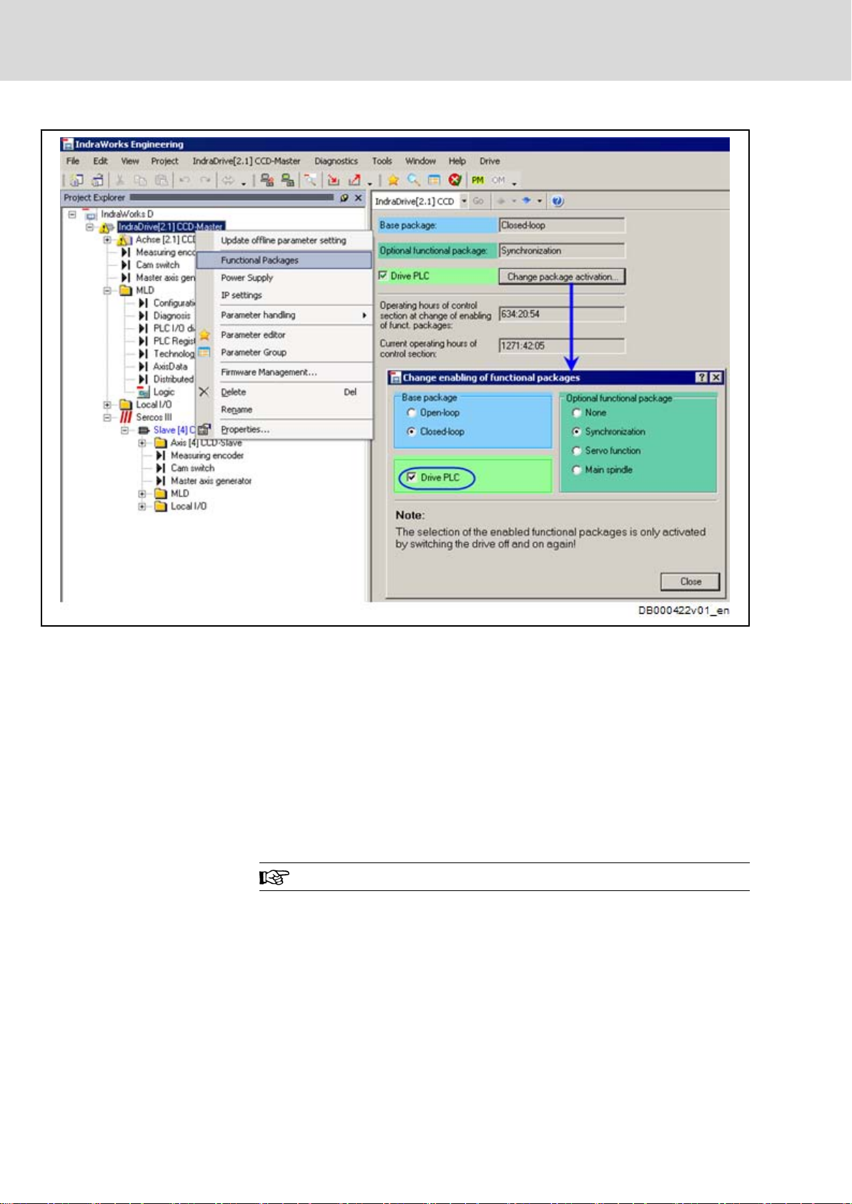
4.2 Enabling of Functional Packages
In addition
"IndraMotion MLD" (drive PLC) must have been enabled in the drive so that
IndraMotion MLD can be used.
to the functional package "Closed Loop", the functional package
18/97
LSA Control S.L. www.lsa-control.com comercial@lsa-control.com (+34) 960 62 43 01
Requirements
Bosch Rexroth AG DOK-INDRV*-MLD-APPLI**-AW02-EN-P
Rexroth IndraDrive Rexroth IndraMotion MLD Application Examples
4.3 Programming
Fig.4-1: IndraWorks Dialog to Enable the Functional Package "IndraMotion
Possible configurations of IndraMotion MLD
● TF: IndraMotion MLD for using the self-contained Bosch Rexroth system
solutions (technology functions) (with MPB firmware)
● ML: IndraMotion MLD for free programming of the single axis; including
the use of the technology functions (with MPH/C firmware)
● MA: IndraMotion MLD Advanced for multi-axis systems (MLD-M) and
turnkey solutions (with MPH/C firmware)
To implement the individual application examples, it might possibly be neces‐
sary to enable another functional package. This will be described within the
corresponding chapter.
We assume
sioning software. For more information, see the following documentations:
● IndraMotion MLD - Getting Started "R911319306"
● Rexroth IndraMotion MLD "R911306084"
MLD" (Drive PLC)
It is only allowed to enable licensed functional packages!
that you basically know how to handle the IndraLogic commis‐
The MLD applications examples are available on the following media:

DOK-INDRV*-MLD-APPLI**-AW02-EN-P
LSA Control S.L. www.lsa-control.com comercial@lsa-control.com (+34) 960 62 43 01
Rexroth IndraDrive Rexroth IndraMotion MLD Application Examples
● Installation data carrier IndraWorks MLD in the "AddOns" directory
● Media directory
Bosch Rexroth AG 19/97
Requirements

20/97
LSA Control S.L. www.lsa-control.com comercial@lsa-control.com (+34) 960 62 43 01
Bosch Rexroth AG DOK-INDRV*-MLD-APPLI**-AW02-EN-P
Rexroth IndraDrive Rexroth IndraMotion MLD Application Examples
DOK-INDRV*-MLD-APPLI**-AW02-EN-P
LSA Control S.L. www.lsa-control.com comercial@lsa-control.com (+34) 960 62 43 01
Rexroth IndraDrive Rexroth IndraMotion MLD Application Examples
Double-Axis Positioning Control (Pick and Place)
Bosch Rexroth AG 21/97
5 Double-Axis Positioning Control (Pick and Place)
5.1 Task Definition – Application Description
5.1.1
General Information
Workpieces are to be moved from one place to another place. The required
axis motions are to be carried out one after the other. In addition, the control
(digital output) and feedback (digital input) of the pneumatic picker are to be
handled via IndraMotion MLD. The procedure is to be started via a switch-key
which is read in at a digital input at the master.
Control ("close" picker, "open" picker) and feedback (picker "closed") for the
pneumatic picker are to be controlled via digital inputs/outputs at the SERCOS
slave. This sets the additional task to access remote inputs/outputs with MLD.
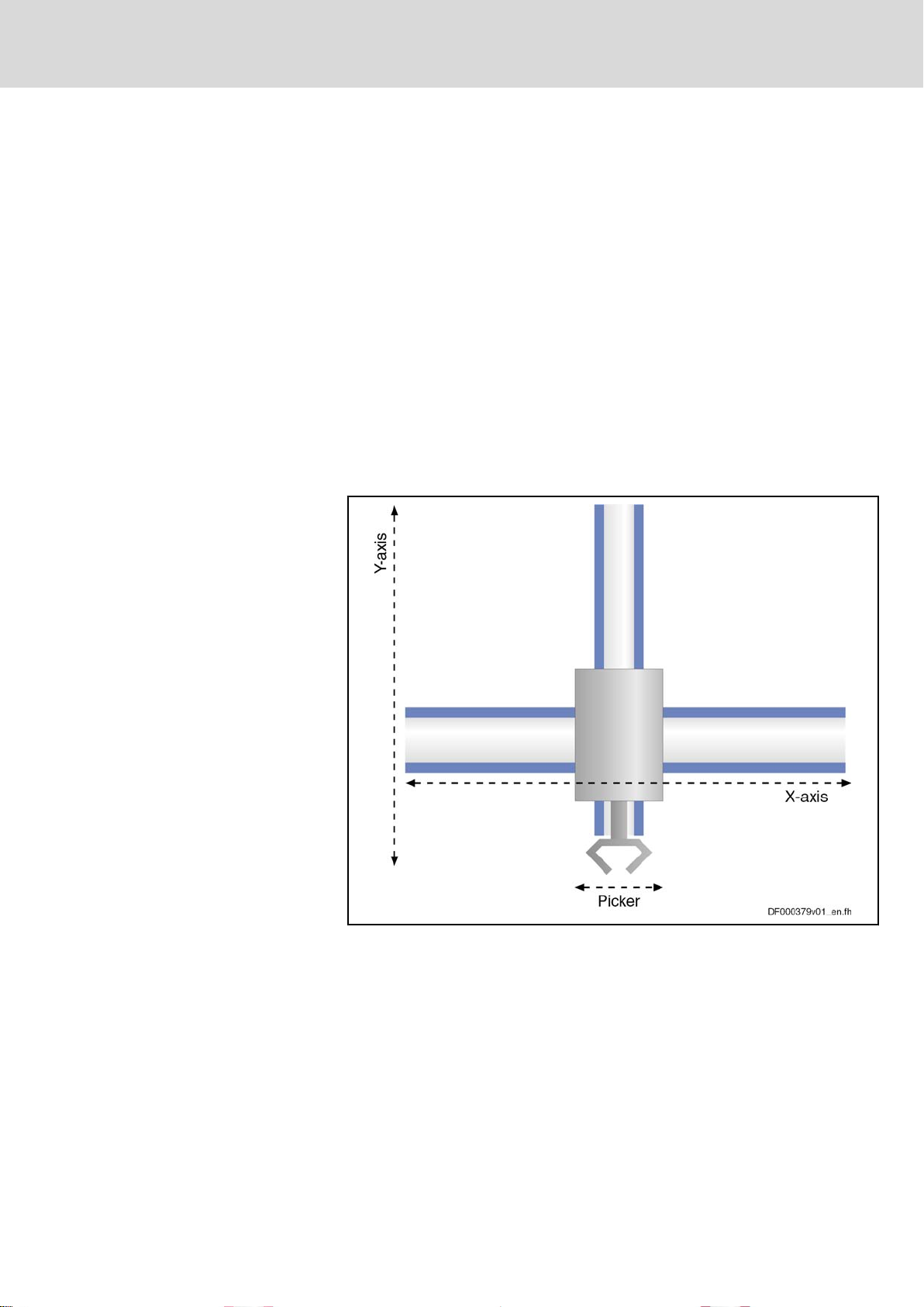
5.1.2 Mechanical Configuration
The figure below illustrates the mechanical scheme of the double-axis posi‐
tioning control "Pick and Place".
Fig.5-1: Mechanical Scheme of the Application "Pick and Place"
22/97
LSA Control S.L. www.lsa-control.com comercial@lsa-control.com (+34) 960 62 43 01
Bosch Rexroth AG DOK-INDRV*-MLD-APPLI**-AW02-EN-P
Double-Axis Positioning Control (Pick and Place)
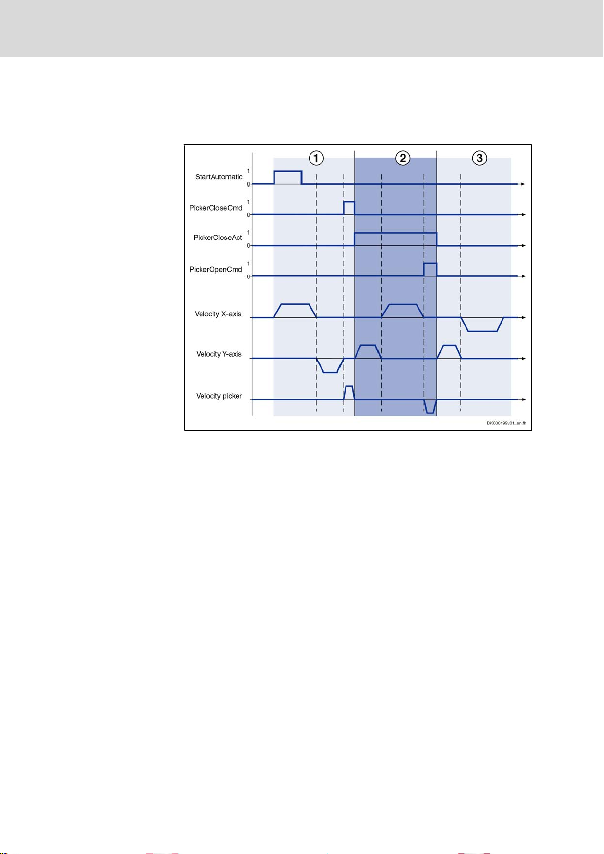
5.1.3 Sequence of Motion
Rexroth IndraDrive Rexroth IndraMotion MLD Application Examples
The chronological
diagram below illustrates the sequence of motion of the dou‐
ble-axis positioning control "Pick and Place".
1 Pick up product
2
3
Fig.5-2: Sequence of Motion of the Application "Pick and Place"
Transport to placing position
Return to start position
Step 1:
Upon a positive edge at the "bStartAutomatic" input (P‑0‑1390, bit 0, %IX0.0),
the X- and Y-axes are switched to enable. The X-axis first and then the Y-axis
move to the picking position. When the 1st positioning process of both axes has
been completed, the "bPickerCloseCmd" output (P‑0‑1411, bit 8, %QX1.8) is
set whereby the picker closes and takes up the workpiece.
Step 2:
When the picker has closed, this is signaled by the feedback "bPickerClo‐
seAct" (P‑0‑1440, bit 1, %IX50.1) and the movement to the placing position is
carried out. In this case, it is first the Y-axis and then the X-axis which is moved.
When the placing position has been reached, the "bPickerOpenCmd" output
(P‑0‑1411, bit 9, %QX1.9) is set upon which the picker opens and places the
workpiece.
Step 3:
The 0-signal of the "bPickerCloseAct" input (P‑0‑1440, bit 1, %IX50.1) signals
that the picker has opened and this triggers the movement to the start position.
For this purpose, it is first the Y-axis and then the X-axis which positions. When
the travel process has been completed, the enable signal is removed at the
axes.
Starting from the basic parameters, you have to make some fundamental set‐
tings for the example of application "Pick and Place". The following paragraphs
will explain these settings in short form.
DOK-INDRV*-MLD-APPLI**-AW02-EN-P
LSA Control S.L. www.lsa-control.com comercial@lsa-control.com (+34) 960 62 43 01
Rexroth IndraDrive Rexroth IndraMotion MLD Application Examples
Bosch Rexroth AG 23/97
Double-Axis Positioning Control (Pick and Place)
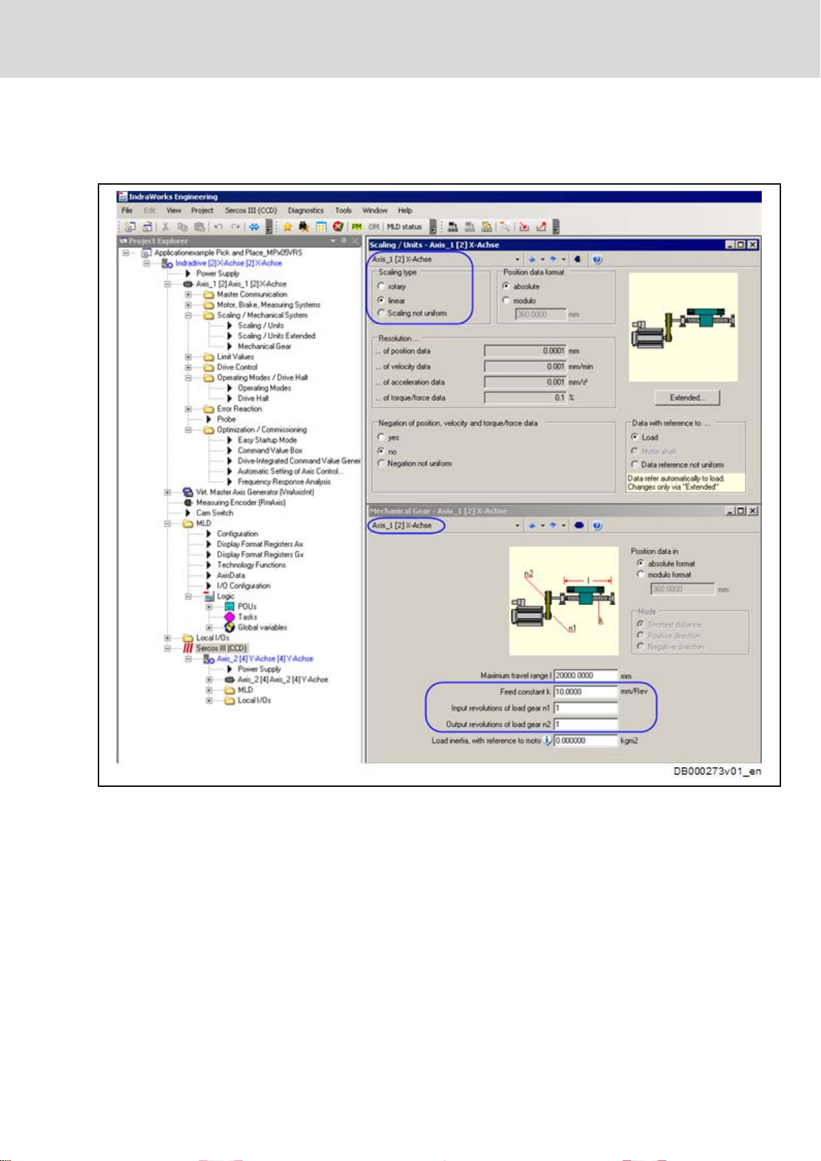
Mechanical Data
According to
the mechanical configuration, you have to set the scaling, gear
and feed constant for the X- and Y-axes.
Fig.5-3: Example: Mechanical Data for X-Axis
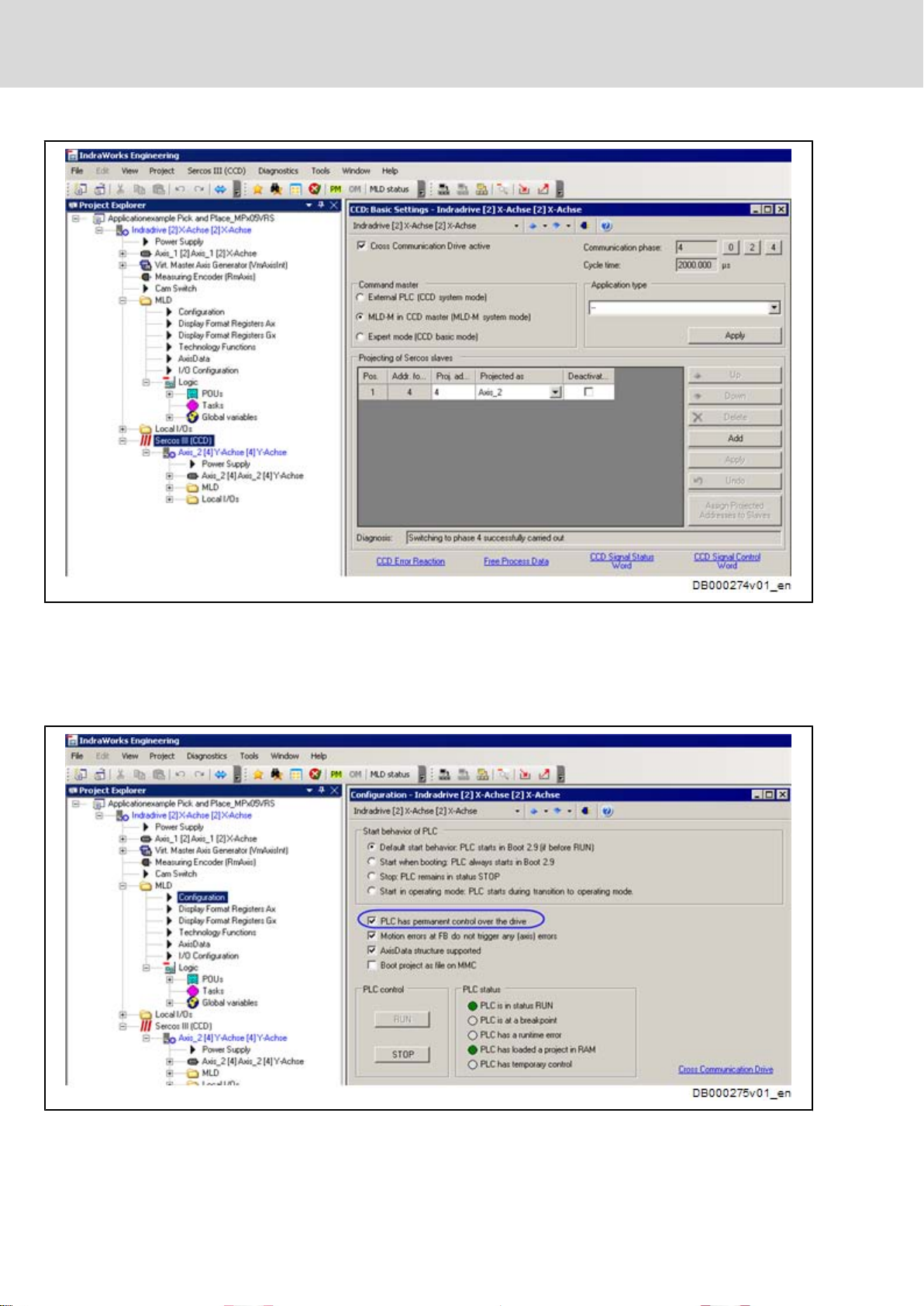
CCD Configuration
First you have to activate the CCD communication and select the MLD-M sys‐
tem mode. The axis with address "4" has been configured as CCD slave (Yaxis).
24/97
LSA Control S.L. www.lsa-control.com comercial@lsa-control.com (+34) 960 62 43 01
Bosch Rexroth AG DOK-INDRV*-MLD-APPLI**-AW02-EN-P
Double-Axis Positioning Control (Pick and Place)
Rexroth IndraDrive Rexroth IndraMotion MLD Application Examples
MLD Configuration
Fig.5-4: IndraWorks Dialog for CCD Settings
The resulting axis addressing in MLD-M is:
● X-axis (axis address 2) → Axis 1 in MLD
● Y-axis (axis address 4) → Axis 2 in MLD
In the drive PLC, you have to select permanent control for the CCD master.
Fig.5-5: IndraWorks Dialog for MLD Configuration
DOK-INDRV*-MLD-APPLI**-AW02-EN-P
LSA Control S.L. www.lsa-control.com comercial@lsa-control.com (+34) 960 62 43 01
Rexroth IndraDrive Rexroth IndraMotion MLD Application Examples
Bosch Rexroth AG 25/97
Double-Axis Positioning Control (Pick and Place)
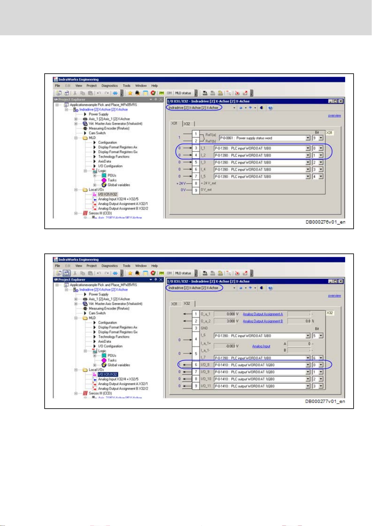
Configuring the Digital Inputs/Out‐
puts at the Master
The digital
inputs and outputs at the terminals X31/32 have to be parameterized
at the X-axis (CCD master) in accordance with the following IndraWorks dialog.
X31.3 P‑0‑1390, bit 0 (%IX0.0) → bStartAutomatic
X31.4 P‑0‑1390, bit 1 (%IX0.1) → bProgramReset
Fig.5-6: Configuration "X31" of X-Axis (CCD Master)
X32.3 P‑0‑1410, bit 0 (%QX0.0) → bPickerActive
Fig.5-7: Configuration "X32" of X-Axis (CCD Master)
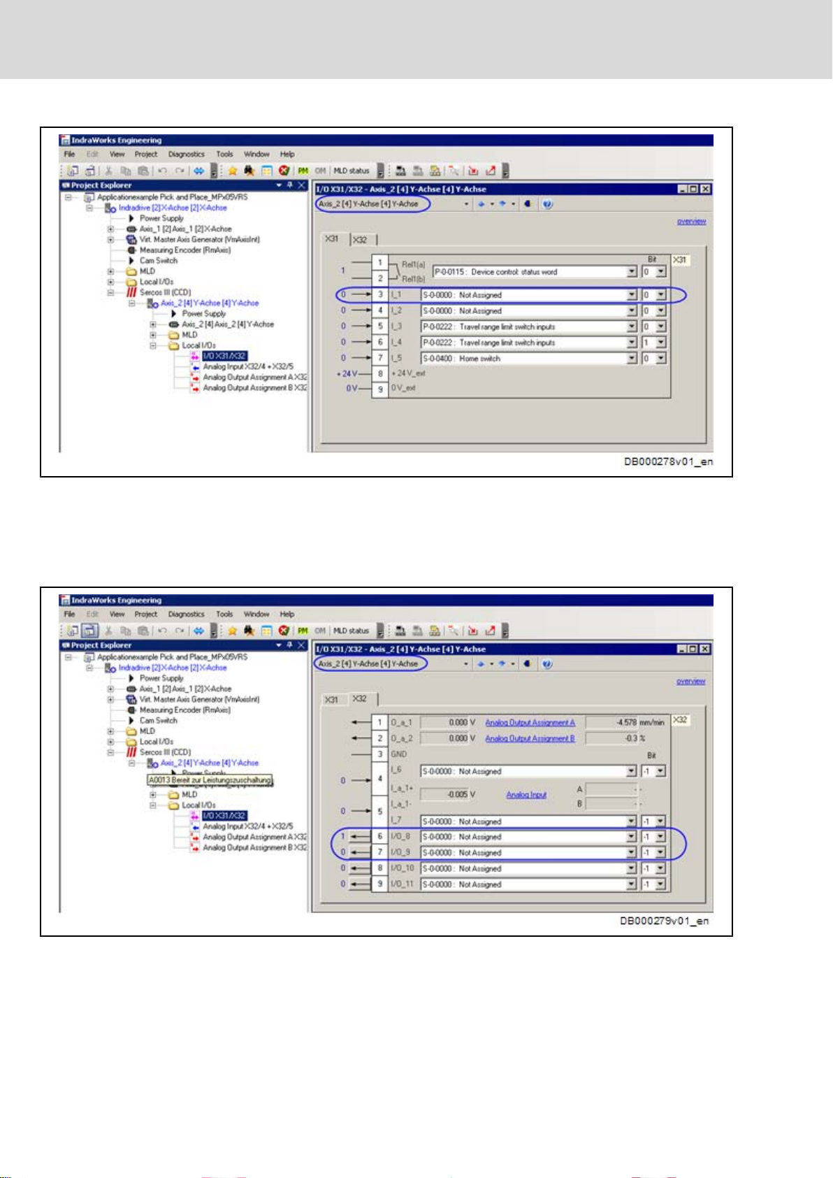
Configuring the Digital Inputs/Out‐
puts at the Slave
The digital inputs and outputs at X31/32 have to be parameterized at the Y-axis
(CCD slave) in accordance with the following IndraWorks dialog.
26/97
LSA Control S.L. www.lsa-control.com comercial@lsa-control.com (+34) 960 62 43 01
Bosch Rexroth AG DOK-INDRV*-MLD-APPLI**-AW02-EN-P
Double-Axis Positioning Control (Pick and Place)
Rexroth IndraDrive Rexroth IndraMotion MLD Application Examples
X31.3 P‑0‑0303, bit 1 → bPickerCloseAct
Fig.5-8: Configuration "X31" of Y-Axis (CCD Slave)
You can simply configure a dummy parameter for the digital input "I_1" of the
CCD slave, because the status of the input is copied directly from parameter
P‑0‑0303 (signal status of the digital inputs) to the CCD master (see also figure
"Configuring the Distributed Inputs/Outputs").
X32.6 P‑0‑0304, → bit 8 bPickerCloseCmd
X32.7 P‑0‑0304, bit 9 → bPickerOpenCmd
Fig.5-9: Configuration "X32" of Y-Axis (CCD Slave)
The digital outputs only have to be configured as outputs and a dummy pa‐
rameter can be assigned to them as it is done for the inputs. The status of the
output is influenced by the CCD master by direct writing of the parameter
DOK-INDRV*-MLD-APPLI**-AW02-EN-P
LSA Control S.L. www.lsa-control.com comercial@lsa-control.com (+34) 960 62 43 01
Rexroth IndraDrive Rexroth IndraMotion MLD Application Examples
P‑0‑0304 (signal status of the digital outputs) (see also figure "Configuring the
Distributed Inputs/Outputs").
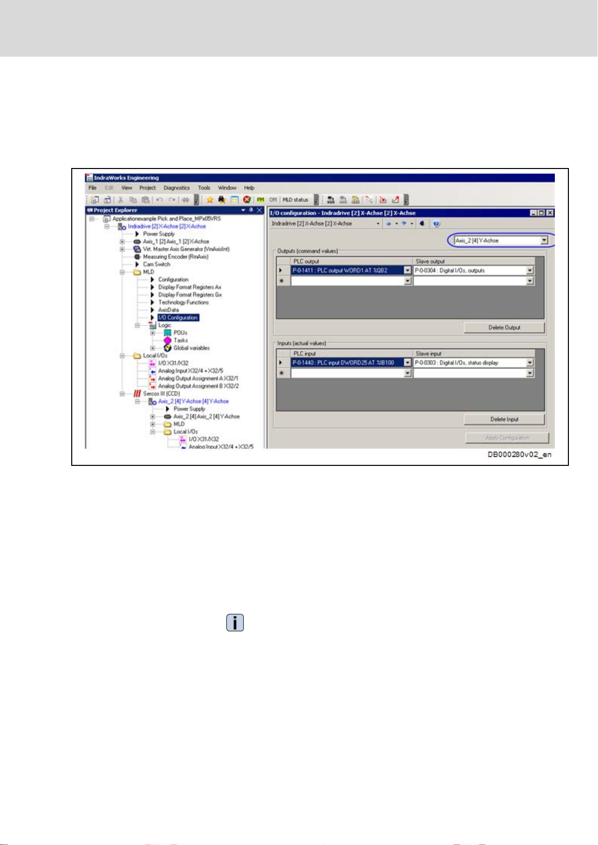
Configuring the "Distributed Inputs/
Outputs"
The
settings shown in the following IndraWorks dialog are required to transmit
the input which has been read in from the Y-axis (CCD slave) to the X-axis
(CCD master) or to set the outputs at the Y-axis (CCD slave) from the MLD-M
of the X-axis (CCD master).
Bosch Rexroth AG 27/97
Double-Axis Positioning Control (Pick and Place)
Fig.5-10: IndraWorks Dialog for Configuring the Distributed Inputs/Outputs
In the application example, the parameter P‑0‑1411 is written by MLD-M. By
the above-mentioned configuration, this parameter directly takes effect on the
status of the digital outputs (P‑0‑0304) in the Y-axis (CCD slave).
The status of the digital inputs of the CCD slave (P‑0‑0303) is copied to the
parameter P‑0‑1440 of the CCD master and evaluated there by MLD-M. As the
parameter P‑0‑0303 is a 32-bit value, it has to be assigned to a 32-bit process
image register, such as parameter P‑0‑1440.
You have to observe in which bits the corresponding terminals take effect. For
example, the output "I/O_8" which is used has to be addressed in the CCD slave
via bit 8 of the parameter P‑0‑0304.
See also Parameter Description for "P‑0‑0303, Digital
I/Os, inputs" and
"P‑0‑0304, Digital I/Os, outputs"
28/97
LSA Control S.L. www.lsa-control.com comercial@lsa-control.com (+34) 960 62 43 01
Double-Axis Positioning Control (Pick and Place)
Bosch Rexroth AG DOK-INDRV*-MLD-APPLI**-AW02-EN-P
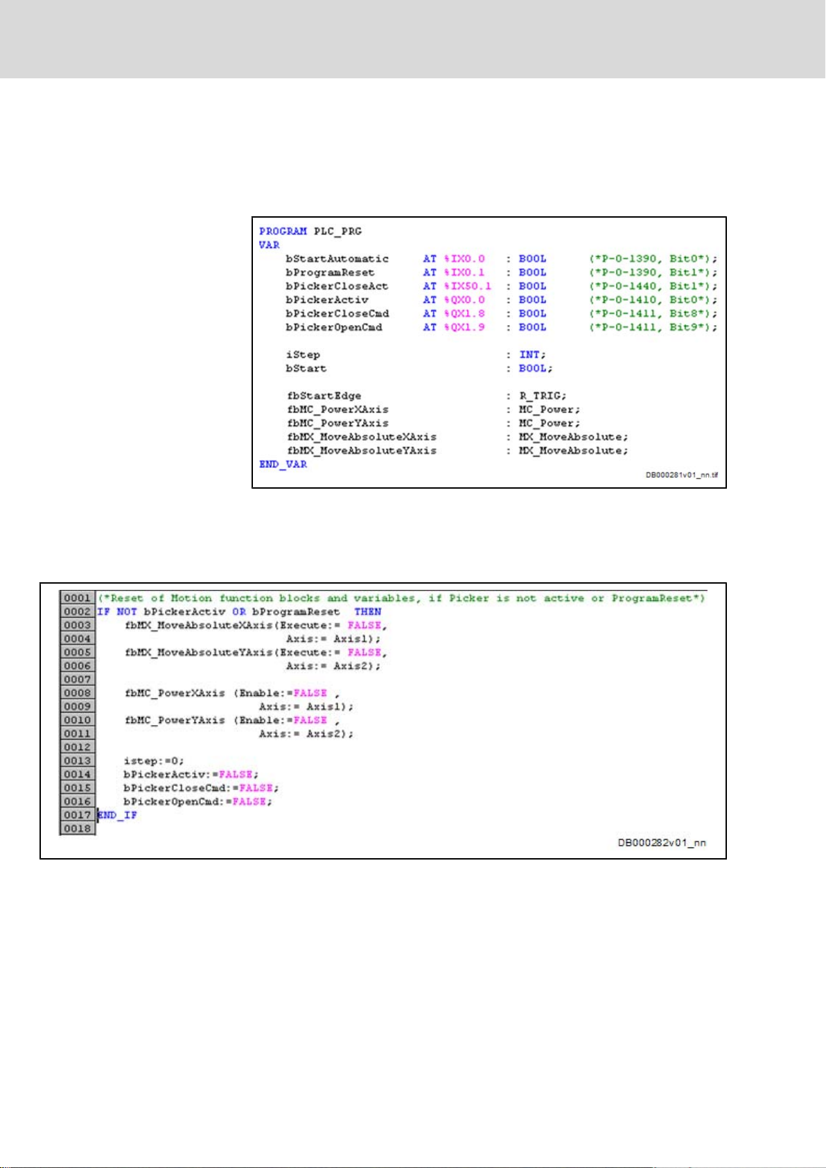
5.2 Programming
1. Variable declaration
variable declaration, the variables which are used are created and
In the
assigned to the inputs and outputs.
Rexroth IndraDrive Rexroth IndraMotion MLD Application Examples
Fig.5-11: Variable Declaration
2. Initialization
In the first initialization step, all variables or function blocks are brought to
a defined status.
Fig.5-12: Initialization
3. Generating the start edge
After a positive edge at the "bStartAutomatic" input (P‑0‑1390, bit 0,
%IX0.0), the automatic sequence of steps is processed.
 Loading...