

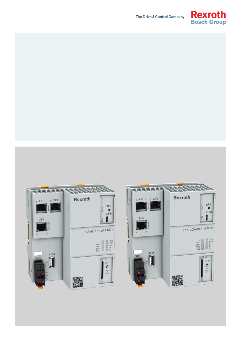
Bosch Rexroth IndraControl XM21, Rexroth IndraControl XM22 Operating Instructions Manual
IndraControl
LSA Control S.L. www.lsa-control.com comercial@lsa-control.com (+34) 960 62 43 01
XM21, XM22
Controls
Operating Instructions
R911340667
Edition 03

Bosch Rexroth AG Controls
LSA Control S.L. www.lsa-control.com comercial@lsa-control.com (+34) 960 62 43 01
Change Record
Edition Release
Notes
Date
Edition 01 2014-07 First edition
Edition 02 2016-08 Revised edition
Edition 03 2017-03 Notes on the explosion protection (Atex) supplemented for XM22
Copyright
© Bosch Rexroth AG 2017
This document, as well as the data, specifications and other information set
forth in it, are the exclusive property of Bosch Rexroth AG. It may not be reproduced or given to third parties without its consent.
Liability
The specified data is intended for product description purposes only and shall
not be deemed to be a guaranteed characteristic unless expressly stipulated in
the contract. All rights are reserved with respect to the content of this documentation and the availability of the product.
Editorial Department
Development automation systems, control platform HP (MK/MePe)
RS-dd09e598460fdd310a6846a501e7d658-3-en-US-3

Controls Bosch Rexroth AG
LSA Control S.L. www.lsa-control.com comercial@lsa-control.com (+34) 960 62 43 01
Table of Contents
Table of Contents
Page
1 About this documentation..................................................................... 1
1.1 Overview on target groups and product phases.................................... 1
1.2 Scope..................................................................................................... 1
1.3 Related documents................................................................................ 2
1.4 Customer feedback................................................................................ 2
2 Product identification and scope of delivery......................................... 2
2.1 Product identification............................................................................ 2
2.2 Scope of delivery................................................................................... 3
3 Use of the safety instructions................................................................ 3
3.1 Structure of the safety instructions....................................................... 3
3.2 Explaining signal words and safety alert symbol................................... 3
3.3 Symbols used......................................................................................... 4
3.4 Signal graphic explanation on the device.............................................. 4
4 Intended Use.......................................................................................... 5
5 Spare parts, accessories and wear parts.............................................. 5
5.1 Power connectors, 24 V......................................................................... 5
5.2 Bus base module for IndraControl XM21/XM22.................................... 6
5.3 Bus base module for IndraControl S20 I/O........................................... 6
5.4 SD card.................................................................................................. 6
5.5 End clamp.............................................................................................. 6
5.6 Wear parts............................................................................................. 6
6 Ambient conditions................................................................................ 6
7 Technical data........................................................................................ 8
7.1 Voltage supply and current consumption.............................................. 9
8 Standards.............................................................................................. 9
8.1 Standards used.................................................................................... 10
8.2 CE marking........................................................................................... 10
8.2.1 Declaration of conformity.................................................................... 10
8.3 UL/CSA certified.................................................................................. 10
8.4 Explosion protection certification (XM2201.01-...).............................. 11
DOK-CONTRL-IC*XM2*****-IT03-EN-P
I

Bosch Rexroth AG
LSA Control S.L. www.lsa-control.com comercial@lsa-control.com (+34) 960 62 43 01
Controls
Table of Contents
Page
8.4.1 Power matrix........................................................................................ 13
8.4.2 Standards used.................................................................................... 13
8.5 Marine and offshore certification (XM2201...).................................... 13
9 Interfaces............................................................................................. 14
9.1 Connection position............................................................................ 14
9.2 Extension bus...................................................................................... 15
9.3 S20 interface....................................................................................... 15
9.4 Control bus base module .................................................................... 15
10 Mounting, demounting and electric installation.................................. 16
10.1 Installation notes................................................................................. 16
10.2 Housing dimensions............................................................................. 18
10.3 Mounting the control........................................................................... 19
10.4 Mounting S20 I/O modules.................................................................. 20
10.5 Mounting extension modules............................................................... 21
10.6 Demounting the control and the control bus base module................. 22
10.6.1 Demounting steps................................................................................ 22
10.7 Electric installation.............................................................................. 24
10.7.1 External power supply unit ................................................................. 24
10.7.2 Voltage supply for the control.............................................................. 25
10.7.3 24 V voltage supply.............................................................................. 26
10.7.4 Grounding
............................................................................................................. 28
10.7.5 Shielding.............................................................................................. 29
11 Commissioning.................................................................................... 29
11.1 Commissioning steps........................................................................... 29
11.2 Establishing a connection to the engineering PC via the USB device
interface "XF31" .................................................................................. 30
12 Device description............................................................................... 33
12.1 LEDs and operating elements.............................................................. 34
12.1.1 LEDs in the XD1 plug........................................................................... 34
12.1.2 LED block of 10................................................................................... 35
12.1.3 Operation mode switches ................................................................... 36
12.1.4 Reset button........................................................................................ 37
12.2 Initial firmware..................................................................................... 38
12.2.1 License information............................................................................. 39
II
DOK-CONTRL-IC*XM2*****-IT03-EN-P

Controls Bosch Rexroth AG
LSA Control S.L. www.lsa-control.com comercial@lsa-control.com (+34) 960 62 43 01
Table of Contents
Page
12.2.2 LED states............................................................................................ 39
12.2.3 Starting and opening the initial firmware............................................ 40
12.2.4 Installing a backup from an external SD card...................................... 41
12.3 Booting................................................................................................ 42
12.4 Fallback and recovery.......................................................................... 42
12.5 IndraControl First Touch...................................................................... 43
12.5.1 Hardware data..................................................................................... 44
12.5.2 Network settings.................................................................................. 44
12.5.3 Firmware management........................................................................ 45
12.5.4 File manager........................................................................................ 50
12.5.5 Core dump........................................................................................... 51
12.6 Backing up remanent data................................................................... 52
12.7 Real-time clock.................................................................................... 52
13 Error causes and troubleshooting........................................................ 53
14 Maintenance........................................................................................ 54
14.1 Regular maintenance tasks.................................................................. 54
15 Ordering information........................................................................... 54
15.1 Type code............................................................................................. 55
15.2 Accessories and spare parts................................................................ 56
16 Disposal............................................................................................... 57
16.1 General Information............................................................................. 57
16.2 Return.................................................................................................. 57
16.3 Packaging............................................................................................. 57
17 Service and support............................................................................ 57
Index.................................................................................................... 59
DOK-CONTRL-IC*XM2*****-IT03-EN-P
III

Bosch Rexroth AG Controls
LSA Control S.L. www.lsa-control.com comercial@lsa-control.com (+34) 960 62 43 01
IV
DOK-CONTRL-IC*XM2*****-IT03-EN-P
Presales Aftersales
Selection
Mounting
(assembly/installation)
Engineering
Commissioning
Operation
Decommissioning
Product
phases
Target
groups
Activities
Design engineer
Programmer
Technologist
Process
specialist
Select
Prepare
Design
Construct
Mechanic/
electrician
Unpack
Mount
Install
Programmer
Commissioning engineer
Parameterize
Program
Configure
Simulate
Technologist
Process specialist
Optimize
Test
Machine
operator
Maintenance
technician
Service
Operate
Maintain
Remove
faults
Create
the NC program
Mechanic/
electrician
Disposal company
Dismount
Dispose
Controls
LSA Control S.L. www.lsa-control.com comercial@lsa-control.com (+34) 960 62 43 01
Bosch Rexroth AG
About this documentation
1 About this documentation
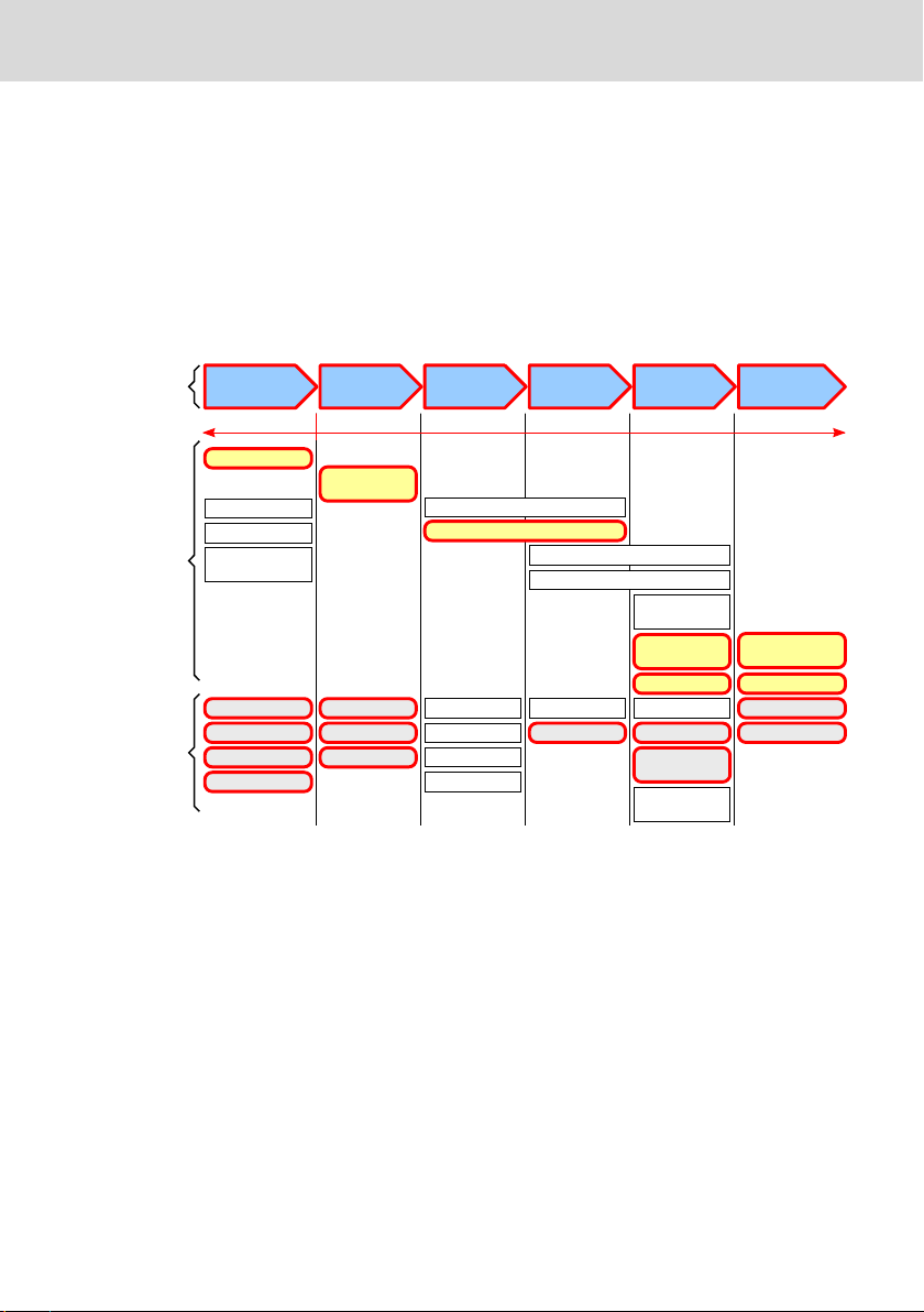
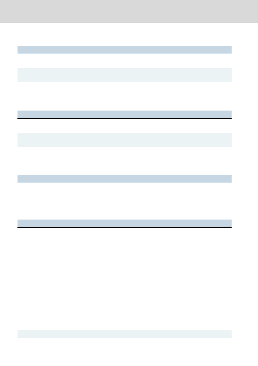
1.1 Overview on target groups and product phases
In the following illustration, the framed activities, product phases and target
groups refer to the present documentation.
Example: In the product phase "Mounting (assembly/installation)", the target
group "mechanic/electrician" can execute the activity "install" using this documentation.
Fig. 1-1:
tivities of the target group
This document instructs the technical staff of the machine manufacturer on how
to safely perform the mechanical and electrical installation and on how to commission the device.
Required qualification: Individual who is able to assess the tasks assigned and
to identify possible safety risks owing to qualification in the subject, knowledge
and experience. The individual should also be familiar with the standards and
regulations.
1.2
Scope
This operating instructions is valid for all variants of the control, whose type codes start with:
XM21...
DOK-CONTRL-IC*XM2*****-IT03-EN-P
Assigning the present documentation to the target groups, product phases and ac-
1/61

(7261)
MNR: R911173147
FD: 13W08
AA1
FI:001
SN: 7260007123456789
IND.CONT.EQ
C
U
17YB
US LISTED
I-C-B-H-T-V
Bosch Rexroth AG, 97816 Lohr, Germany
Made in Germany
17
8
3
21 5
11
10
9
13
12
16
15
4 76
14
1 Wortmarke
2 Materialnummer
3 Typenbezeichnung
4 Prüfziffer
5 Fertigungsdatum jjWww
6 Änderungsstand
7 Schutzart des Gehäuses
8 CE-Konformitätskennezeichen
9 Werksnummer
10 Rexroth-Barcode
11 Seriennummer
12 UL-Kennzeichen
13 Bemessungsstrom
14 Bemessungsspannung
15 Firmenanschrift
16 MAC-Adresse, MAC-Adresse al Barcode
UN DC 24 V
IN 0,6 A
Bosch Rexroth AG
LSA Control S.L. www.lsa-control.com comercial@lsa-control.com (+34) 960 62 43 01
Controls
Product identification and scope of delivery
XM22...
The type code specifications are located on the type plate of the device. Also re-
fer to chapter 2 "Product identification and scope of delivery" on page 2.
1.3 Related documents
Title Part number and document type
Rexroth IndraControl S20:
System and Installation
Rexroth IndraControl S20:
Diagnostic Tabs and Error Messages
Tab. 1-1: Related documents
The XM2x controls are provided as function package with the systems
IndraMotion MLC and IndraMotion MTX. The ordering data (type code, part
number) differ according to the selected function package (system functions).
The hardware characteristics described in this document apply to all available
function packages. For more information on the function packages, refer to the
respective system descriptions.
For related documents, go to the "Rexroth Media Directory" at http://
www.boschrexroth.com.
R911335988
Application Description
R911344826
Application Description
1.4 Customer feedback
Customer requests, comments or suggestions for improvement are of great importance to us. Please email your feedback on the documentations to Feed-
back.Documentation@boschrexroth.de. Directly insert comments in the elec-
tronic PDF document and send the PDF file to Bosch Rexroth.
2
Product identification and scope of delivery
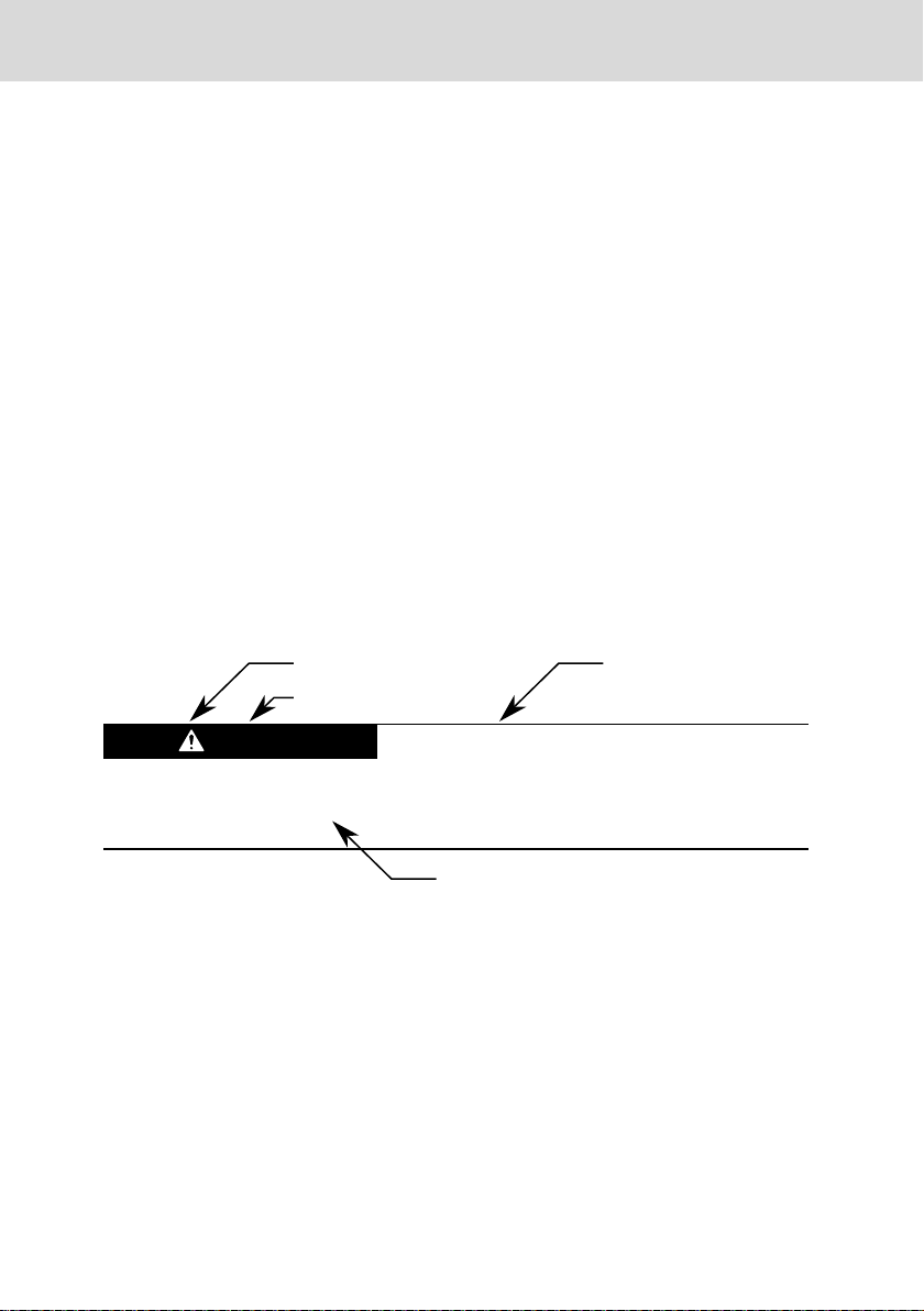
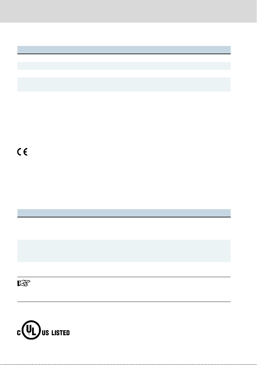
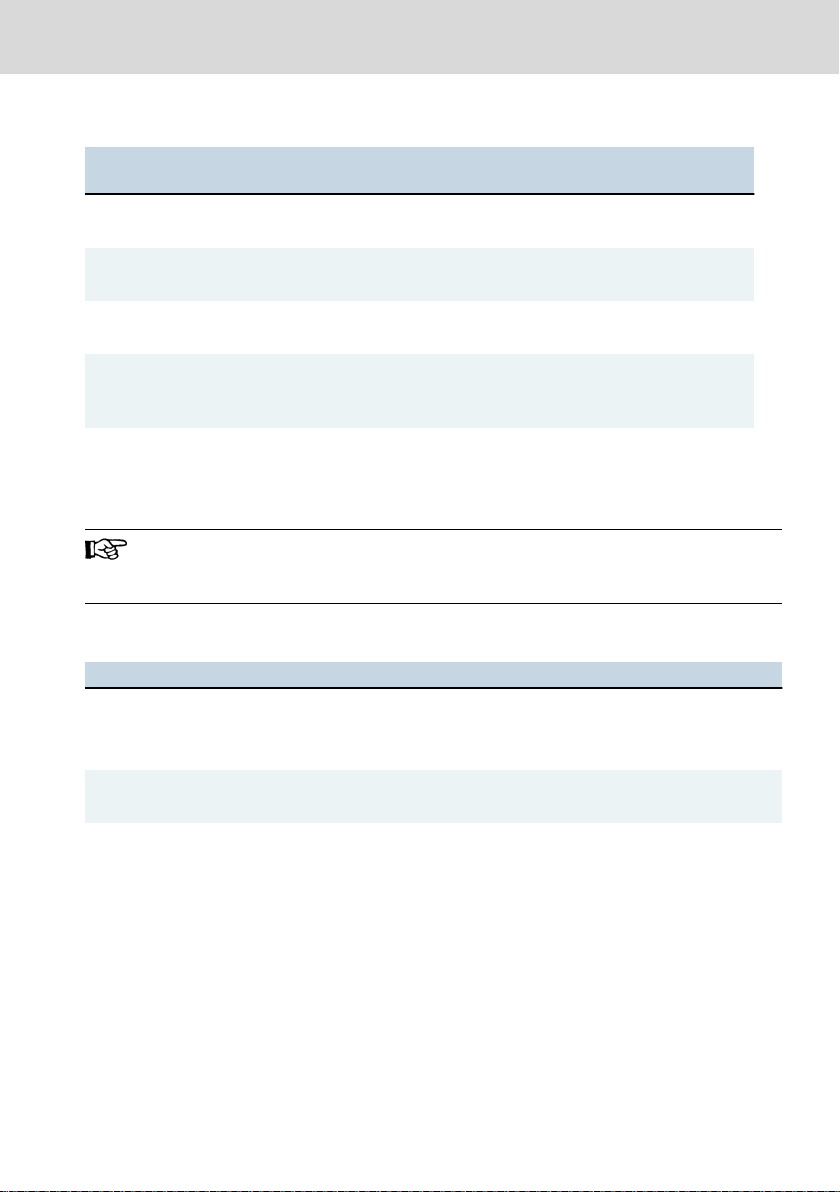
2.1 Product identification
1 Word mark
2 Part number
2/61
3 Type name (type code)
4 Check digit
DOK-CONTRL-IC*XM2*****-IT03-EN-P
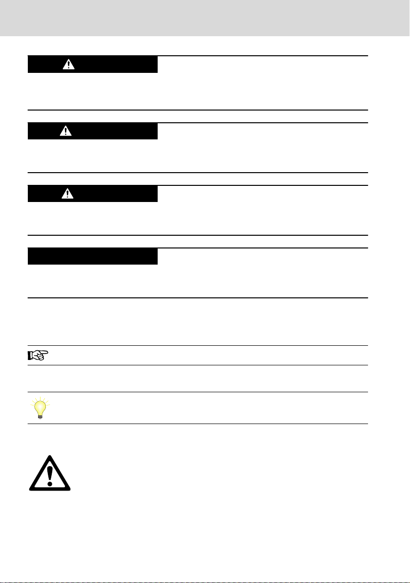
Burns and chemical burns due to wrong
battery treatment!
CAUTION
Safety alert symbol
Signal word
Consequences and
source of danger
Avoiding danger
Do not open the batteries and do not heat them over 80 °C.
Controls
LSA Control S.L. www.lsa-control.com comercial@lsa-control.com (+34) 960 62 43 01
Bosch Rexroth AG
Use of the safety instructions
5 Date of manufacture (yyWww)
6 State of revision
7 CE conformity marking
8 Plant number
9 QR code
10 Serial number
11 Underwriters Laboratories Inc. mark
Fig. 2-1: Exemplary type plate
12 Nominal current
13 Nominal voltage
14 Company address
15 MAC address, MAC address as barcode
16 Functional index
17 Manufacturing country
2.2 Scope of delivery
● IndraControl XM21 or IndraControl XM22
● 24 V power connector XA-CN01
● Bus base module:
– XA-BS01 (for S20 connection right)
– XA-BS02 (for S20 connection right and extension modules left)
3
Use of the safety instructions
3.1 Structure of the safety instructions
The safety instructions are structured as follows:
Fig. 3-1: Structure of the safety instructions
3.2 Explaining signal words and safety alert symbol
The safety instructions in this documentation contain specific signal words (danger, warning, caution, notice) and, if necessary, a safety alert symbol (according
to ANSI Z535.6-2006).
The signal word is used to draw attention to the safety instruction and also provides information on the severity of the hazard.
The safety alert symbol (a triangle with an exclamation point), which precedes
the signal words danger,warning and caution is used to alert the reader to personal injury hazards.
DOK-CONTRL-IC*XM2*****-IT03-EN-P
3/61
DANGER
WARNING
CAUTION
NOTICE
krax
Bosch Rexroth AG
LSA Control S.L. www.lsa-control.com comercial@lsa-control.com (+34) 960 62 43 01
Controls
Use of the safety instructions
In case of non-compliance with this safety instruction, death or serious injury
will occur.
In case of non-compliance with this safety instruction, death or serious injury
can occur.
In case of non-compliance with this safety instruction, minor or moderate injury
can occur.
In case of non-compliance with this safety instruction, material damage can occur.
3.3 Symbols used
Hints are represented as follows:
This is an information.
Tips are represented as follows:
This is a tip.
3.4 Signal graphic explanation on the device
Prior to the installation and commissioning of the device, refer to the
device documentation.
4/61
DOK-CONTRL-IC*XM2*****-IT03-EN-P

NOTICE
Controls Bosch Rexroth AG
LSA Control S.L. www.lsa-control.com comercial@lsa-control.com (+34) 960 62 43 01
Spare parts, accessories and wear parts
4 Intended Use
Danger of device damage if not the expressly
stated accessories, mounting parts, components, cables, lines, software and firmware are
used.
The IndraControl XM21/XM22 control may only be used with the accessories
and mounting parts listed in this documentation. Components that are not expressly mentioned must neither be attached nor connected. The same applies to
cables and lines.
Only to be operated with the component configurations and combinations expressly defined and with the software and firmware specified in the corresponding functional description.
Typical areas of application of the IndraControl XM21/XM22 are:
● Handling systems and assembly systems
● Packaging and food processing machines
● Printing machines and paper converting machines
● Machine tools
● Wood working machines
The IndraControl XM21/XM22 control may only be operated under the mounting
and installation conditions, the position, and the ambient conditions (temperature, degree of protection, humidity, EMC etc.) specified in the related documentation.
5
Spare parts, accessories and wear parts
5.1 Power connectors, 24 V
Ordering code Part number Description
XA-CN01 R911173741 24 V plug
Tab. 5-1: Power connectors, 24 V
DOK-CONTRL-IC*XM2*****-IT03-EN-P
5/61
Bosch Rexroth AG
LSA Control S.L. www.lsa-control.com comercial@lsa-control.com (+34) 960 62 43 01
Ambient conditions
Controls
5.2 Bus base module for IndraControl XM21/XM22
Ordering code Part number Description
XA-BS01 R911342346 Bus base module for IndraControl S20 connection
XA-BS02 R911342347 Bus base module for IndraControl S20 connection
Tab. 5-2: Bus base modules IndraControl XM21/XM22
(right)
(right) and extension modules (left)
5.3 Bus base module for IndraControl S20 I/O
Ordering code Part number Description
S20-BS R911172540 Bus base module for wide IndraControl S20 I/O mod-
S20-BS-S R911173203 Bus base module for narrow IndraControl S20 I/O mod-
Tab. 5-3: Bus base modules for S20 I/O
ules
ules
5.4 SD card
Ordering code Part number Description
XA-SD01 R911173844 SD card 1 GB
Tab. 5-4: SD card
5.5 End clamp
Ordering code Part number Description
SUP-M01-ENDHALTER R911170685 2 pieces of snap-on end brackets for 35 mm NS 35/7.5
Tab. 5-5: End clamp
or NS 35/15 carrier plate; width: 9.5 mm
5.6 Wear parts
There are no wear parts in the controls IndraControl XM21 and XM22.
6
Ambient conditions
Ambient temperature in operation Up to 2,000 m: -25 °C to +60 °C
2,000 m to 3,000 m: max. +55 °C
3,000 m to 4,000 m: max. +50 °C
4,000 m to 4,700 m: max. +45 °C
Ambient temperature during storage and transport -30 °C to +85 °C
6/61
DOK-CONTRL-IC*XM2*****-IT03-EN-P

NOTICE
NOTICE
Controls
LSA Control S.L. www.lsa-control.com comercial@lsa-control.com (+34) 960 62 43 01
Bosch Rexroth AG
Ambient conditions
Operating altitude Up to 4,700 m above sea level acc. to DIN 60204
Permitted air humidity 5 % to 95 % acc. to DIN EN 61131-2, no conden-
sation
Degree of protection IP20 acc. to DIN EN 60 529
Protection class III, DIN EN 61010-2-201
Overvoltage category 2
Contamination level 2, no condensation allowed
Mechanical tests
①
Vibration resistance acc. to DIN EN 60068-2-6
Oscillations, sinusoidal in all three axes
5 Hz - 9 Hz with 3.5 mm amplitude
9 Hz -150 Hz with 5 g peak acceleration
Shock test acc. to DIN EN 60068-2-27 Shock stress: Shock resistance in all three axes,
11 ms semi-sinusoidal 30 g
Broadband noise acc. to DIN EN 60068-2-64
5-20-150 Hz with 0.572 g, 5 h per axis
Electrostatic discharge
ESD resistance acc. to DIN EN 61131-2
● Test voltage
Criterion B
8 kV for air discharge
6 kV for contact discharge
① The vibration stress specifications assume the use of industrial-suited RJ45 plug connec-
tions. The "Industrial RJ45 plug" of the company Yamaichi is recommended (Y-ConPlug-41). The cables are available as accessories (RKB0020). To protect against vibration,
secure the cables with a short distance (< 20 cm). The USB interfaces XF30 and XF31
may only be used up to a vibration stress of 1 g.
Tab. 6-1: Ambient conditions
Failure of the product due to contaminated air
● The ambient air must not contain acids, alkaline solutions, corrosive agents,
salts, metal vapors and other electrically conductive contaminants in high
concentrations
● Housing and installation compartments must at least comply with the degree
of protection IP 54 according to DIN EN 60529
Defective product due to gases jeopardizing
functions
Due to the risk of corrosion, avoid sulphurous gases (e.g. sulphur dioxide (SO2)
and hydrogen suphide (H2S)). The product is not resistant against these gases.
DOK-CONTRL-IC*XM2*****-IT03-EN-P
7/61

NOTICE
Bosch Rexroth AG
LSA Control S.L. www.lsa-control.com comercial@lsa-control.com (+34) 960 62 43 01
Controls
Technical data
Failure of the product due to overheating
To avoid overheating and to ensure a smooth operation of the product according
to the minimum distances specified in chapter 10.1 "Installation notes" on page
16, air has to circulate.
This is a product that corresponds to the limit values of the emitted
interference of class A (industrial environments), but not of class B
(residential area and small enterprises).
When using the product in residential areas or small enterprises, the
operator has to take actions to prevent radio interferences (also refer to DIN EN 55022).
7
Technical data
Processor IndraControl XM21: Intel E620T 600 MHz (CPU frequency)
IndraControl XM22: Intel E660T 1300 MHz (CPU frequency)
RAM 512 MB DRAM
Connection for extension mod-
Via the control bus base module XA-BS02
ules
Extension bus
Number of possible modules 3
Connection for S20 I/O Via control bus base module XA-BS01 or XA-BS02
S20 bus parameters
Transmission rate
Number of connectable mod-
ules
100 MBit/s
Max. 63 (per station)
2 A
Max. current for the S20 bus
(U
)
Bus
Communication interfaces RJ45 connections:
● 1 × Ethernet connection (10 MB, 100 MB, 1 GB)
● 2 × Sercos III master/slave interface
USB ports:
● 1 × USB host, maximum cable length 3 m (for the functionality,
refer to the system description of the respective system)
● 1 × USB device, maximum cable length 3 m (for the functionality,
refer to the system description of the respective system)
SD card Slot for SD card
8/61
DOK-CONTRL-IC*XM2*****-IT03-EN-P

NOTICE
Controls
LSA Control S.L. www.lsa-control.com comercial@lsa-control.com (+34) 960 62 43 01
Bosch Rexroth AG
Standards
Weight 0.38 kg (incl. supply connectors)
Dimensions Refer to chapter 10.2 "Housing dimensions" on page 18
Tab. 7-1: Technical data
7.1 Voltage supply and current consumption
The following values apply to the operating voltage acc. to DIN EN 61131-2:
Nominal voltage at U
LS
Maximum voltage range of the supply voltage allowed U
LS
Current consumption of the control incl. the connected S20 I/O modules from ULS at nominal volt-
age
Current consumption of the control without the
connected S20 I/O modules from ULS at nominal
voltage
Power consumption of the control incl. the connected S20 I/O modules from ULS at nominal volt-
age
Power consumption of the control without the con-
nected S20 I/O modules from ULS at nominal voltage
Reverse voltage protection of the supply voltage Diode
Fuse protection Internal protective fuse, 2.5 A
Transient protection
Pulse load up to 1,500 W
Voltage dips at current supply interfaces PS2 < 10 ms, evaluation criterion A
Electrical isolation
24 V supply ULS to the functional earth
24 V DC SELV/PELV
18 V DC to 31.2 V DC (incl. all tolerances and ripple)
Maximum 1.5 A
Typically 1.0 A
Maximum 36 W
Typically 24 W
Present, suppressor diodes
No separation between 0 V of the ULS and FE
(housing)
Tab. 7-2: Operating voltage and current consumption
Electronic damage due to polarity reversal or
due to a nominal current that is too low
The power supply unit has to be able to deliver the quadruple nominal current of
the protective fuse to ensure that the fuse reliably triggers in case of an error.
8
Standards
The products have been developed according to the German edition of the
standards published at the time of product engineering.
DOK-CONTRL-IC*XM2*****-IT03-EN-P
9/61
Bosch Rexroth AG
LSA Control S.L. www.lsa-control.com comercial@lsa-control.com (+34) 960 62 43 01
Controls
Standards
8.1 Standards used
Standard Meaning Edition
IEC 60204-1 Electrical equipment of machines 2007
IEC 61131-2 Programmable controllers 2008
IEC 60529 Degrees of protection provided by enclosures (IP Code) 2014
IEC 61010-2-201 Safety requirements for electrical equipment for measure-
2014
ment, control and laboratory use
UL 61010-2-201 Safety requirements for electrical equipment for measure-
2014
ment, control and laboratory use
Tab. 8-1: Standards used
8.2 CE marking
8.2.1 Declaration of conformity
The electronic products described in the present operating instructions comply
with the requirements and the target of the following EU directive and with the
following harmonized European standards:
EMC directive 2014/108/EC
The electronic products described in the present operating instructions are in-
tended for use in industrial environments and comply with the following requirements:
Standard
DIN EN 61000-6-4 Electromagnetic compatibility (EMC)
DIN EN 61000-6-2 Electromagnetic compatibility (EMC)
Title Edition
September
Part 6-4: Generic standards – Emission standard for indus-
2011
trial environments
March 2006
Part 6-2: Generic standards – Immunity for industrial environments
Tab. 8-2: Standards for electromagnetic compatibility (EMC)
Loss of CE conformity due to modifications at the device.
CE marking applies only to the device upon delivery. After modifying
the device, verify the CE conformity.
8.3 UL/CSA certified
10/61
DOK-CONTRL-IC*XM2*****-IT03-EN-P
II 3G
Ex ec IIC T4 Gc
TÜV 16 ATEX 7948 X
IECEx TUR 16.0048 X
Controls
LSA Control S.L. www.lsa-control.com comercial@lsa-control.com (+34) 960 62 43 01
Bosch Rexroth AG
Standards
The devices are certified acc. to
● UL 61010-2-201 (Industrial Control Equipment) and
● CSA22.2 No. 61010-2-201 (CSA)
However, there can be combinations or extension stages with a limited or missing certification. Thus, verify the registration according to the UL marking on the
device.
Loss of UL/CSA conformity due to modifications at the device.
UL and CSA marking applies only to the device upon delivery. After
modifying the device, verify the UL and the CSA conformity.
To guarantee an UL/CSA-compliant operation, the following conditions have to be fulfilled:
● Use only insulated copper wire suitable for at least 60/75°C
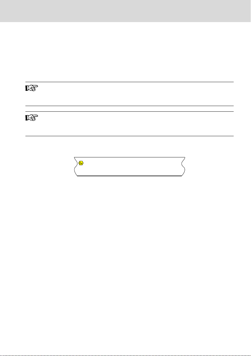
8.4 Explosion protection certification (XM2201.01-...)
Ex Explosion protection label
II Equipment group II: Explosive gas
3G Equipment category 3: Explosive at-
Ex Explosion protection label
ec Type of protection "Increased safety"
IIC Gas group IIC, hydrogen
T4 Maximum surface temperature
Fig. 8-1: Exemplary type plate
atmospheres
mosphere (zone 2)
135 °C
Gc Equipment protection level (EPL),
TÜV... ATEX EU type examination certificate
IECEx... IECEx certificate number
...X Note on special conditions, refer to
rare and momentary explosive atmosphere (zone 2): Flammable
gases, vapors, mists
the following note.
The approval numbers given on the type plate are marked at the end with an "X"
for devices and a "U" for components. "X" indicates special conditions to be observed together with the safety and health regulations given in the standards.
"U" indicates a component (Ex component) that may not be used on its own.
DOK-CONTRL-IC*XM2*****-IT03-EN-P
11/61
DANGER
DANGER
Bosch Rexroth AG
LSA Control S.L. www.lsa-control.com comercial@lsa-control.com (+34) 960 62 43 01
Standards
Observe the following special conditions for a safe operation of the
devices and components:
● The explosion protection approval applies only to the control
XM2201.01-....
● The explosion protection approval is only valid if the devices and
components approved by Bosch Rexroth are used as intended, refer to chapter 4 "Intended Use" on page 5.
● The XM22 control may only be used together with the additional
components and accessories approved by Bosch Rexroth. Otherwise, the explosion protection approval does not apply.
● In case of unintended modifications at the device or at the com-
ponents, the explosion protection approval does also not apply.
For maintenance and troubleshooting, refer to chapter 14 "Main-
tenance" on page 54 and chapter 13 "Error causes and troubleshooting" on page 53.
● The XM22 control may only be used in an area with the minimum
pollution degree 2 as defined in IEC 60991-1.
● For the permitted ambient temperature range, refer to chapter 6
"Ambient conditions" on page 6.
● The XM22 control may only be installed in a housing (control cabi-
net) providing at least an ingress protection of IP54 in compliance
with IEC 60079-0.
● Take suitable actions to ensure that the supply voltage outside the
device or the component is always within the permitted voltage
range (±10%) acc. to EN 60079-0.
● Maintenance and repair work may only be carried out by the certi-
fied Rexroth service.
● Always store and transport the device or the component in the
original package.
Controls
Explosion hazard
Working at the device is only permitted if there is no explosive atmosphere.
Explosion hazard when exceeding or falling below the ambient temperature
Do not exceed the ambient temperature permitted, refer to chapter 6 "Ambient
conditions" on page 6
12/61
DOK-CONTRL-IC*XM2*****-IT03-EN-P
Controls
LSA Control S.L. www.lsa-control.com comercial@lsa-control.com (+34) 960 62 43 01
8.4.1 Power matrix
Bosch Rexroth AG
Standards
Devices and com-
Max. internal current consumption Max. internal power consumption
ponents
XM2201.01.-......
1500 mA 36.0 W
R911173148
XFE01.1-FB-03
200 mA 4.8 W
R911173397
XFE01.1-FB-20
200 mA 4.8 W
R911173957
S20-AI6-AO2-
100 mA 2.4 W
SSI2
R911173120
S20-PWM-4-T
400 mA 9.6 W
R911173461
Tab. 8-3: Power matrix of the XM22 control and the approved components
If the housing surface (control cabinet) is 1m2, up to 87 W of internal power consumption of the individual devices and components
are permitted.
8.4.2 Standards used
Standard Title
EN 60079-0:2012 + A11:2013
IEC 60079-0:2011, modified + Corr.:2012
+ Corr.:2013
EN 60079-7:2015
IEC 60079-7:2015
Explosive atmospheres –
Part 0: Equipment –
General requirements
Explosive atmospheres –
Part 7: Equipment protection by increased safety "e"
Tab. 8-4: Standard used for explosion protection
8.5 Marine and offshore certification (XM2201...)
The control XM2201 ... is suitable for the use in marine and offshore applications and was approved by the following certification organizations:
● DNV-GL Det Norske Veritas, Germanischer Lloyd DCTC_30826-001
● ABS American Bureau of Shipping DCTC_30826-002
● RINA Registro Italiano Navale DCTC_30826-003
● LR Lloyd's Register DCTC_30826-004
● BV Bureau Veritas DCTC_30826-005
DOK-CONTRL-IC*XM2*****-IT03-EN-P
13/61
1 2
8
67
5
3
9
4
NOTICE
Bosch Rexroth AG
LSA Control S.L. www.lsa-control.com comercial@lsa-control.com (+34) 960 62 43 01
Interfaces
● BSH Bundesamt für Seeschifffahrt und Hydrographie DCTC 30826-006
For more information, refer to www.boschrexroth.com/dcc/Vornavi-
gation/VorNavi.cfm?PageID=p650746.
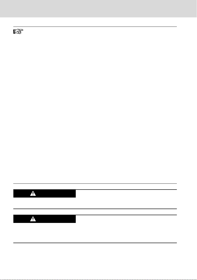
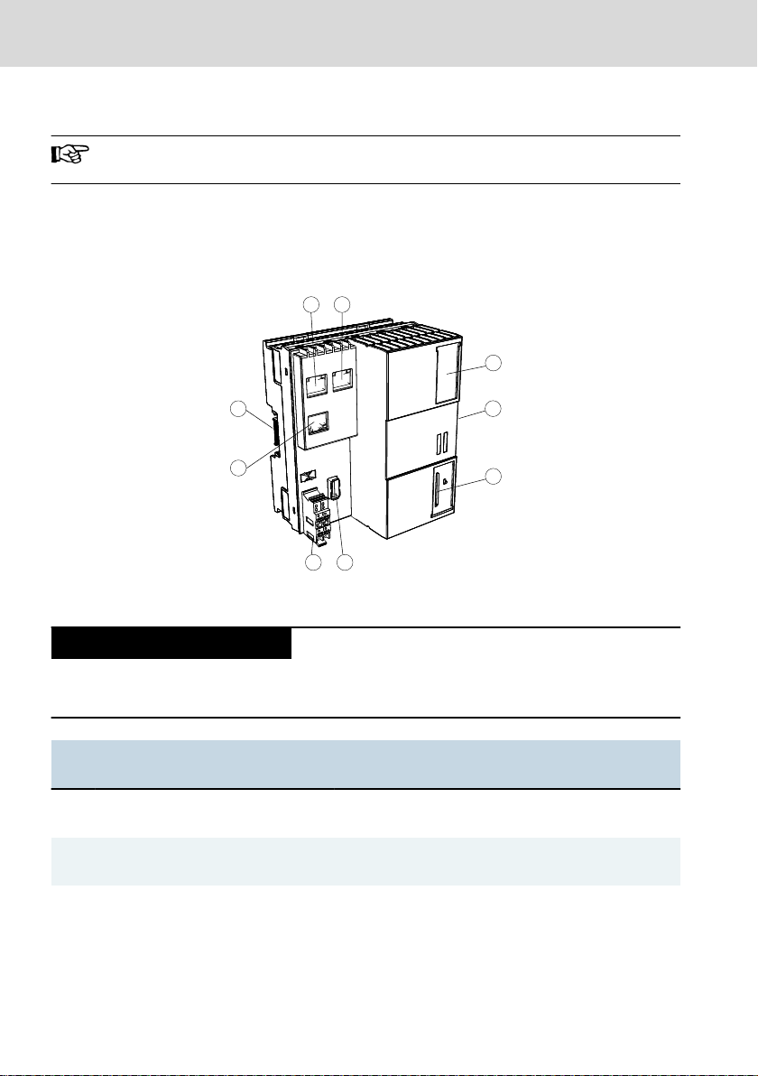
9 Interfaces
9.1 Connection position
Controls
Fig. 9-1: Interfaces
Attaching and detaching connections under
voltage can damage the control!
Switch off the supply voltage before attaching or detaching any connections!
Name Connection type Connector type
No.
(Integrated)
① XF1 Ethernet
(Sercos)
② XF2 Ethernet
(Sercos)
③ XF31 USB device
14/61
USB 2.0
RJ45 socket
8-pin
RJ45 socket
8-pin
Micro USB socket
4-pin
Mating connector and cable
(From outside)
RJ45 plug
(Twisted pair, 8-wire)
RJ45 plug
(Twisted pair, 8-wire)
Micro USB plug
(4-wire)
DOK-CONTRL-IC*XM2*****-IT03-EN-P

Controls
LSA Control S.L. www.lsa-control.com comercial@lsa-control.com (+34) 960 62 43 01
Bosch Rexroth AG
Interfaces
No. Name Connection type Connector type
(Integrated)
④ S20 bus Bus base module
32-pin
Mating connector and cable
(From outside)
Bus base module for S20 I/O
modules
32-pin
⑤ SD Slot for SD card – SD card
⑥ XF30 USB host
USB 2.0
⑦ XD1 24 V plug
U
LS
⑧ XF5 Ethernet
(TCP/IP, RT Ethernet)
⑨ Extension bus Bus base module
USB TYPE A-socket
4-pin
USB TYPE A-plug
(4-wire)
4-pin (4-wire)
RJ45 socket
8-pin
RJ45 plug
(Twisted pair, 4-/8-wire)
Bus base module for exten-
32-pin
sion modules
32-pin
Tab. 9-1: Control interfaces
9.2 Extension bus
Up to three extension modules can be freely connected at the left of the control.
The extension modules have to be attached without any gaps via the extension
bus base modules on the left side of the IndraControl XM21/XM22 and supplied
with the same 24 V supply voltage. Switch on and off the 24 V supply voltage of
the extension modules synchronously with the IndraControl XM21/XM22.
9.3
S20 interface
Up to 63 S20 modules can be connected to the S20 interface on the right of the
IndraControl XM21/XM22 via S20 bus base modules. The number of connectable modules depends on the total current consumption of the S20 modules. The
IndraControl XM21/XM22 can provide up to 2 A for the power supply of the S20
modules.
9.4
Control bus base module
The control bus base module is connected at the bottom side of the
IndraControl XM21/XM22. The control bus base module is available in two variants:
● BUSMODUL XA-BS01 connects the IndraControl XM21/XM22 with the S20
modules on the right control side
● BUSMODUL XA-BS02 connects the IndraControl XM21/XM22 with the S20
modules on the right control side and the extension modules on the left control side
DOK-CONTRL-IC*XM2*****-IT03-EN-P
15/61
 Loading...