

Bosch Rexroth IndraControl VR 21, Rexroth IndraControl VR 21 Singletouch, Rexroth IndraControl VR2109 Singletouch, Rexroth IndraControl VR2104 Singletouch, Rexroth IndraControl VR2107 Singletouch Operating Instructions Manual
...
Electr ic Drives
and Co ntrols Pneuma tics
Hydrau lics
Linear Motion and
Assemb ly Technolo gies
Servic e
Rexroth IndraControl
VR 21
Operating Panel
Operating Instructions
R911339476
Edition 02
Bosch Rexroth AG VR 21
Record of Revision
Edition
Release Date Notes
First edition 09.2013 -Edition 02 04.2014 Revision
Copyright
© Bosch Rexroth AG 2014
This document, as well as the data, specifications and other information set
forth in it, are the exclusive property of Bosch Rexroth AG. It may not be reproduced or given to third parties without its consent.
Liability
The specified data is intended for product description purposes only and shall
not be deemed to be a guaranteed characteristic unless expressly stipulated in
the contract. All rights are reserved with respect to the content of this documentation and the availability of the product.
Editorial Department
Development Automation Systems Control Hardware CV (KaWa/PiGe)
RS-188e285b0a9b33770a6846a50164e9a6-2-en-US-4

VR 21 Bosch Rexroth AG
Table of Contents
Table of Contents
Page
1 About this Documentation..................................................................... 1
2 Product Identification and Scope of Delivery........................................ 2
2.1 Product Identification............................................................................ 2
2.2 Scope of Delivery................................................................................... 2
3 Using the Safety Instructions................................................................. 3
3.1 Safety Instructions – Structure.............................................................. 3
3.2 Explaining Signal Words and Safety Alert Symbol................................. 3
3.3 Symbols Used........................................................................................ 4
4 Intended Use.......................................................................................... 4
5 Spare Parts, Accessories and Wear Parts.............................................. 5
5.1 External 24 V Power Supply Unit .......................................................... 5
5.2 Wear Parts............................................................................................. 5
6 Ambient Conditions............................................................................... 6
7 Technical Data....................................................................................... 6
7.1 VR 21 Singletouch.................................................................................. 6
7.2 VR 21 Multitouch................................................................................... 7
8 Standards.............................................................................................. 8
8.1 General Information............................................................................... 8
8.2 Used Standards..................................................................................... 8
8.3 CE Marking............................................................................................. 9
8.3.1 Declaration of Conformity .................................................................... 9
8.4 UL/CSA Certified................................................................................... 9
9 Interfaces............................................................................................. 10
9.1 Interface View...................................................................................... 10
9.2 Interface Overview............................................................................... 10
9.3 DC 24 V Voltage Supply....................................................................... 11
9.4 USB Interfaces X9, X10........................................................................ 11
9.5 Ethernet Interface X5........................................................................... 12
9.6 Slot for SD Memory Card..................................................................... 12
DOK-SUPPL*-VR21**.01**-IT02-EN-P
I

Bosch Rexroth AG
VR 21
Table of Contents
Page
10 Assembly, Disassembly and Electrical Installation.............................. 13
10.1 Housing Dimensions............................................................................ 13
10.1.1 Front View............................................................................................ 13
10.1.2 Overview of Housing Dimensions - Side View...................................... 14
10.2 Installation Notes................................................................................. 14
10.3 Mounting Cut-Out................................................................................ 15
10.4 Mounting Dimensions.......................................................................... 16
10.5 Disassembly......................................................................................... 16
10.6 Electrical Wiring................................................................................... 16
10.6.1 Connecting the Supply Voltage............................................................ 16
10.6.2 Connecting the Functional Earth (FE)................................................. 17
11 Commissioning.................................................................................... 18
12 Device Description............................................................................... 18
12.1 General Information............................................................................. 18
12.2 Control and Display Elements.............................................................. 19
12.2.1 Display................................................................................................. 19
12.2.2 Touchscreen........................................................................................ 19
12.2.3 Real-Time Clock .................................................................................. 19
12.3 Variants................................................................................................ 19
13 Error Causes and Elimination.............................................................. 20
14 Maintenance........................................................................................ 20
14.1 General Information............................................................................. 20
14.2 Display................................................................................................. 20
14.3 Cleaning Notes..................................................................................... 21
14.4 Fuse..................................................................................................... 21
14.5 Regular Maintenance Tasks................................................................. 21
15 Ordering Information........................................................................... 21
15.1 Accessories and Spare Parts............................................................... 21
15.2 Type Code VR21xx.01.......................................................................... 22
16 Disposal............................................................................................... 22
16.1 Take-Back............................................................................................. 22
16.2 Packaging............................................................................................. 23
II
DOK-SUPPL*-VR21**.01**-IT02-EN-P

VR 21 Bosch Rexroth AG
Table of Contents
Page
17 Service and Support............................................................................ 23
Index.................................................................................................... 25
DOK-SUPPL*-VR21**.01**-IT02-EN-P
III

Bosch Rexroth AG VR 21
IV
DOK-SUPPL*-VR21**.01**-IT02-EN-P
Presales Aftersales
Selection
Mounting
(assembly/installation)
Engineering
Commissioning
Operation
Decommissioning
Product
phases
Target
groups
Activities
Design engineer
Programmer
Technologist
Process
specialist
Select
Prepare
Design
Construct
Mechanic/
electrician
Unpack
Mount
Install
Programmer
Commissioning engineer
Parameterize
Program
Configure
Simulate
Technologist
Process specialist
Optimize
Test
Machine
operator
Maintenance
technician
Service
Operate
Maintain
Remove
faults
Create
the NC program
Mechanic/
electrician
Disposal company
Dismount
Dispose
VR 21
Bosch Rexroth AG
About this Documentation
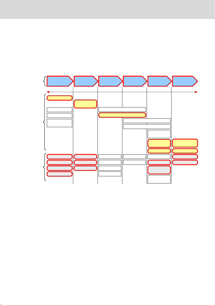
1 About this Documentation
Overview – target groups and product phases
The activities, product phases and target groups that refer to the present docu-
mentation are marked in red color in the following figure.
Example: In the product phase "Mounting (assembly/installation)", the "mechan-
ic/electrician" can execute the activity "install" using this documentation.
Fig. 1-1: Assigning the present documentation to the target groups, product phases and activities of the target group
Purpose
This document instructs the technical staff of the machine manufacturer on how
to perform the mechanic and electrical installation in a safe way and on how to
commission the device.
Required qualifications: Individual who is able to assess the tasks assigned and
identify possible safety risks owing to qualification in the subject, knowledge
and experience. The individual should also be familiar with the standards and
regulations.
Scope
This document is valid for all variants whose type code starts with "VR21xx.
01…".
The type code specifications are located on the type plate of the device, see al-
so chapter 2.1 "Product Identification" on page 2.
DOK-SUPPL*-VR21**.01**-IT02-EN-P
1/29

1
5
12
9
7
2
3
4
11
8
10
6
Bosch Rexroth AG
VR 21
Product Identification and Scope of Delivery
Further documents
Title Part number and document type
Rexroth IndraControl
VAP 01
R911339613
Operating Instructions
Power Supply Unit
Rexroth IndraControl
V Devices
R911343901
Project Planning Manual
Operating Systems
Tab. 1-1: Required and supplementing documentation
Customer feedback
Customer requests, comments or suggestions for improvement are of great im-
portance to us. Please email your feedback on the documentations to Feed-
back.Documentation@boschrexroth.de. Directly insert comments in the elec-
tronic PDF document and send the PDF file to Bosch Rexroth.
2
Product Identification and Scope of Delivery
2.1 Product Identification
The type plate is located on the rear panel.
1 Logotype
2 Part number
3 State of revision
4 Date of manufacture (yyWww)
5 Division or plant number
6 Designation of origin
Fig. 2-1: Type plate IndraControl VR 21
2.2 Scope of Delivery
● Product insert "Safety and Warning Instructions"
2/29
7 Nominal current
8 Serial number as barcode
9 Company address
10 Serial number
11 Nominal voltage
12 Type code (type designation code)
DOK-SUPPL*-VR21**.01**-IT02-EN-P

Burns and chemical burns due to wrong
battery treatment!
CAUTION
Safety alert symbol
Signal word
Consequences and
source of danger
Avoiding danger
Do not open the batteries and do not heat them over 80 °C.
DANGER
WARNING
VR 21
● Six mounting brackets including tool
● 24 V female connector strip
3 Using the Safety Instructions
3.1 Safety Instructions – Structure
The safety instructions are structured as follows:
Fig. 3-1: Safety instructions – Structure
Bosch Rexroth AG
Using the Safety Instructions
3.2 Explaining Signal Words and Safety Alert Symbol
The safety instructions in this documentation contain specific signal words (danger, warning, caution, notice) and, if necessary, a safety alert symbol (according
to ANSI Z535.6-2006).
The signal word is meant to draw the reader's attention to the safety instruction
and signifies the degree of danger.
The safety alert symbol (a triangle with an exclamation point), which precedes
the signal words danger,warning and caution is used to alert the reader to personal injury hazards.
In case of non-compliance with this safety instruction, death or serious injury
will occur.
In case of non-compliance with this safety instruction, death or serious injury
can occur.
DOK-SUPPL*-VR21**.01**-IT02-EN-P
3/29

CAUTION
NOTICE
NOTICE
Bosch Rexroth AG
Intended Use
In case of non-compliance with this safety instruction, minor or moderate injury
could occur.
In case of non-compliance with this safety instruction, property damage could
occur.
VR 21
3.3 Symbols Used
Notes are displayed as follows:
This is a note.
Tips are displayed as follows:
This is a tip.
4 Intended Use
The IndraControl VR 21 devices by Bosch Rexroth are machine operator panels
that can, depending on the application, visualize control data and trigger functions at the machine.
Danger of destruction of the device if not expressly stated accessories, mounting parts and
other components, cables, lines, software and
firmware are used
The machine operator panels may be used only as intended and with the accessories, mounting parts, and other components specified in this documentation.
Components that are not expressly mentioned must neither be attached nor
connected. The same applies to cables and lines.
Operation must only be carried out with the hardware component configurations and combinations that are expressly specified and with the software and
firmware indicated and specified in the respective documentation and functional descriptions.
Typical areas of application of the machine operator panels are:
● Handling systems and assembly systems
4/29
DOK-SUPPL*-VR21**.01**-IT02-EN-P

VR 21
Bosch Rexroth AG
Spare Parts, Accessories and Wear Parts
● Packaging and food processing machines
● Printing machines and paper converting machines
● Machine tools
● Wood processing machines
The machine operator panels may only be operated under the mounting and installation conditions, the position, and the ambient conditions (temperature, degree of protection, humidity, EMC etc.) specified in this documentation.
5 Spare Parts, Accessories and Wear Parts
5.1 External 24 V Power Supply Unit
Order code Parts number Description
VAP01.1H-W23-024-010-NN R911171065 External 24 V power supply unit for the
Tab. 5-1: External 24 V power supply unit for the operating panel
5.2 Wear Parts
Wear parts are not subject to any warranty.
Backlight
The service life of the backlight is limited. After this time has been exceeded,
the backlight will produce only 50 % of its original brightness. The service life of
the following table refers to an ambient temperature of 25 °C.
Display size
107.95 mm (4.3") 40,000 hours
177.8 mm (7") 40,000 hours
228.6 mm (9") 70,000 hours
IndraControl V devices
Service life
Tab. 5-2: Half-life period of the TFT displays
Touch screen
After 3 million touches, no damage or malfunction have occured under the fol-
lowing conditions:
Touch element: R8, HS40 silicone rubber
Touch pressure: 150 g
Touch frequency: 3 Hz
DOK-SUPPL*-VR21**.01**-IT02-EN-P
5/29

Bosch Rexroth AG
Technical Data
6 Ambient Conditions
In operation Transport Storage
Max. ambient
temperature
Humidity Min. relative humidity: 20
Air pressure Up to 3000 m above sea level acc. to EN 61131-2
Mechanical
strength
Contamination
level
Overvoltage
category
+0 ℃ to +50 ℃ -25 ℃ to +70 ℃
Min. relative humidity: 20
%
Max. relative humidity:
85 %
Condensation not allowed
Max. vibration:
Frequency range: 10 Hz to
150 Hz
Excursion: 0.075 mm at
10 Hz to 57 Hz
%
Max. relative humidity:
75 %
Condensation not allowed
Max. shock:
15 g 11 ms
acc. to EN 60068-2-27,
no disturbance of the function
Acceleration: 1 g at 57 Hz
to 150 Hz
acc. to EN 600068-2-6
2
3 -
Min. relative humidity:
20 %
Max. relative humidity:
85 %
Condensation not allowed
VR 21
Tab. 6-1: Ambient conditions
7
Technical Data
7.1 VR 21 Singletouch
VR2104 Singletouch VR2107 Singletouch VR2109 Singletouch
Display 107.95 mm TFT (4.3")
480 × 272 pixels
65536 colors
Brightness 450 cd/m
Display
53,8 × 95 (H × B)
Touch technology Analog resistive, 4-wire technology
Touch activation pres-
15 g (standard) with R8 HS60 silicone rubber
sure
Housing Sheet steel, zinc-coated
6/29
177.8 mm TFT (7")
800 × 480 pixels
262144 colors
2
Brightness 350 cd/m
Display
91.4 × 152.4 (H × B)
228.6 mm TFT (9")
800 × 480 pixels
16.77 million colors
2
Brightness 360 cd/m
Display
117 × 195 (H × B)
DOK-SUPPL*-VR21**.01**-IT02-EN-P
2

VR 21 Bosch Rexroth AG
Technical Data
VR2104 Singletouch VR2107 Singletouch VR2109 Singletouch
Front panel material Aluminium, brushed, naturally anodized
Enclosure rating Front panel IP 65 according to DIN EN 60 529, rear side IP 20
Central processing unit ARM Cortex™-A8, 800 MHz with real-time clock
Flash memory 256 MByte
LPDDR memory 512 MByte
Voltage supply DC 24 V (use a 24 V power supply unit according to DIN EN 60742, classifi-
cation VDE 0551, for example the power supply unit VAP01.1HW23-024-010-NN, part number R911171065)
Current consumption 0.2 A (typically at 24 V)
0.3 A (maximum)
0.3 A (typically at 24 V)
0.4 A (maximum)
0.6 A (typically at 24 V)
0.7 A (maximum)
Connection value 4.8 W 7.2 W 14.4 W
Fuse Semiconductor fuse, resettable
Reverse voltage protec-
Integrated
tion
USB Per USB port max. 500 mA, total current at all USB ports is max. 1 A.
Weight Approx. 0.6 kg Approx. 0.8 kg Approx. 1.3 kg
Tab. 7-1: Technical data of the VR 21 Singletouch
7.2 VR 21 Multitouch
VR2107 Multitouch VR2109 Multitouch
Display 177.8 mm TFT (7")
800 × 480 pixels
262144 colors
Brightness 350 cd/m
2
Display 91.4 × 152.4 (H × B)
Touch technology Projected capacitive, can be operated with finger
Touch activation pressure 15 g (standard) with R8 HS60 silicone rubber
Housing Sheet steel, zinc-coated
Front panel material Aluminium, brushed, naturally anodized
Surface of the front panel Glass
Enclosure rating Front panel IP 65 according to DIN EN 60 529
Rear panel IP 20
Central processing unit
ARM CortexTM-A8, 800 MHz with real-time clock
Flash memory 256 MByte
LPDDR memory 512 MByte
DOK-SUPPL*-VR21**.01**-IT02-EN-P
228.6 mm TFT (9")
800 × 480 pixels
16.77 million colors
Brightness 360 cd/m
Display 117 × 195 (H × B)
2
7/29

Bosch Rexroth AG
Standards
VR2107 Multitouch VR2109 Multitouch
Voltage supply DC 24 V (use a 24 V power supply unit according to DIN EN 60742,
Current consumption 0.4 A (typically at 24 V)
Connection value 9.6 W 16.8 W
Fuse Semiconductor fuse, resettable
Reverse voltage protection Integrated
USB Per USB port max. 500 mA, total current at all USB ports is max. 1
Weight Approx. 0.8 kg Approx. 1.3 kg
Tab. 7-2: Technical data of the VR 21 Multitouch
8
Standards
classification VDE 0551, for example the power supply unit
VAP01.1H-W23-024-010-NN, part number R911171065)
0.7 A (typically at 24 V)
0.5 A (maximum)
A.
0.8 A (maximum)
VR 21
8.1 General Information
The products have been developed according to the current German edition of
the standards at the time of product development.
8.2 Used Standards
Standard Meaning
DIN EN 61000-4-2, DIN EN
61000-4-3
DIN EN 61000-4-4, DIN EN
61000-4-5
DIN EN 61000-4-6, DIN EN
61000-6-2
DIN EN 61000-6-3 Interference emission
DIN EN 61131-2 Equipment requirements
DIN EN 61131-2 Storage and transport
DIN EN 61131-2 Power supply
2004/108/EC Electromagnetic compatibility
DIN EN 60529 Degrees of protection
DIN EN 60068-2-27 Impact load, shock
DIN EN 60068-2-6 Sinusoidal vibrations
Tab. 8-1: Used Standards
8/29
Noise immunity
DOK-SUPPL*-VR21**.01**-IT02-EN-P

VR 21
Bosch Rexroth AG
Standards
8.3 CE Marking
8.3.1 Declaration of Conformity
The electronic products that are described in the present instructions, comply
with the requirements and the target of the following EU directive and with the
following harmonized European standards:
EMC Directive 2004/108/EC
The electronic products described in the present instructions are intended for
use in industrial environments and comply with the following requirements:
Standard Title Edition
DIN EN 61131-2 Programmable logic controllers 2008+B1:2010
DIN EN 61000-6-2 Electromagnetic Compatibility (EMC)
Part: 6-2: Generic standards – Immunity for industrial environments
DIN EN 61000-6-3 Electromagnetic Compatibility (EMC)
Part: 6-3: Generic standards - Emission standard for residential environments
Tab. 8-2: Standards for electromagnetic compatibility (EMC)
2006+B1:2011
2007+A1:2011
Non-compliance with CE conformity due to modifications to the device.
The CE marking is only valid for the device in its delivery status. After having modified the device, the CE conformity is to be verified.
8.4 UL/CSA Certified
The devices are certified according to
● UL508 (Industrial Control Equipment) and
● C22.2 No. 142-M1987 (CSA)
UL file no. E210730
However, there can be combinations or extension stages with limited or missing
certification. Thus, verify the registration according to the UL marking on the device.
DOK-SUPPL*-VR21**.01**-IT02-EN-P
9/29

X9
X10X5
X1
1
2
Bosch Rexroth AG
Interfaces
Loss of UL/CSA conformity due to modifications to the device.
The UL and CSA marking is only valid for the device in its delivery
status. After modifying the device, the UL and CSA conformity is to
be verified.
9 Interfaces
9.1 Interface View
VR 21
① SD memory card
② Functional earth ground
Fig. 9-1: IndraControl VR 21 interfaces
9.2 Interface Overview
Designation at
the housing
X1 DC-24-V voltage supply 3-pin, Phoenix MINI
X9, X10 USB
host
X5 Ethernet 10/100 Base-T RJ45 female connector RJ45 connector
Functional
earth ground
SD memory
card
Tab. 9-1: Interfaces
10/29
Connection type Connector type, integra-
2 USB interfaces USB female connector,
Functional earth ground Tab connector Receptacle
SD and SDHC memory card slot -
ted
COMBICON
4-pin, type A
Mating connector or cable (from outside)
3-pin, FK-MCP 1,5/3ST-3,5
USB connector,
4-pin, type A
DOK-SUPPL*-VR21**.01**-IT02-EN-P

NOTICE
X1
1 2
3
VR 21 Bosch Rexroth AG
Interfaces
Malfunctions due to insufficient shielding!
Use only shielded cables and metallic or conductive connector/coupling covers
with large-area shield support.
9.3 DC 24 V Voltage Supply
Cables with a cross section of 0.75 to 2.5 mm2 can be connected to the connection terminal.
Fig. 9-2: Power supply connector X1
Pin Designation Function
1 Low-noise earth, functional earth (FE)
2 0 V Supply voltage 0 V (GND)
3 24 VDC 24 VDC supply voltage
Use a 24 V industrial power supply unit acc. to DIN EN 60742, classification VDE
0551, for example "VAP01.1H-W23-024-010-NN" (parts number R911171065) for
the voltage supply.
9.4 USB Interfaces X9, X10
Two USB host interfaces are available at the operating device.
Operation of the USB ports at the operating device
When using input devices not intended for industrial use (e.g. keyboard, mouse), the operational safety is limited. Input devices intended for home or office use are also part of the devices not intended
for industrial use.
Connect only USB devices that meet the USB2.0 specification.
For the specification of a suitable cable, refer to "Universal Serial
Bus Specification Rev. 2.0".
The max. cable length is 2.5 m.
DOK-SUPPL*-VR21**.01**-IT02-EN-P
11/29

Bosch Rexroth AG
Interfaces
Not all USB devices are recognized.
The operating system does not support all USB devices. Devices that
require a special USB driver, which is not integrated in the system,
cannot be operated at the USB interfaces.
9.5 Ethernet Interface X5
A 10/100Base-T Ethernet interface is provided at the operating device.
Use a twisted-pair cable of category 5 or 6 (CAT 5 or 6). The max.
cable length is 100 m.
Ethernet interface – Status and diagnostic displays
LED ACT/LNK (green)
● On: Connection to network is available
● Off: No connection
● Flashing: Communication is running
LED SPD 10/100 (yellow)
● On: 100 MBit/s mode
● Off: 10 MBit/s mode or connection disconnected
VR 21
9.6 Slot for SD Memory Card
An SD card can be inserted at the bottom of the operating device.
When using hardware not intended for industrial use (e.g. keyboard,
mouse, memory card) in an industrial environment, the operational
safety is limited. Hardware intended for home or office use is also
part of the devices not intended for industrial use.
Inserting the memory card
Insert the memory card with the front facing the top. Insert the card until the
memory card engages.
Fig. 9-3:
12/29
Inserting the memory card
DOK-SUPPL*-VR21**.01**-IT02-EN-P

1
2
VR 21 Bosch Rexroth AG
Assembly, Disassembly and Electrical Installation
Removing the memory card
Insert the memory card in the operating device until it engages. Remove the un-
locked memory card.
10 Assembly, Disassembly and Electrical Installation
10.1 Housing Dimensions
10.1.1 Front View
①, ② See the following table
Fig. 10-1: IndraControl VR 21 front view
Device ①Height ②Width
VR2104 100 mm 140 mm
VR2107 150 mm 211 mm
VR2109 178 mm 263 mm
Tab. 10-1: Front dimensions
DOK-SUPPL*-VR21**.01**-IT02-EN-P
13/29

2
1
3
Bosch Rexroth AG
Assembly, Disassembly and Electrical Installation
10.1.2 Overview of Housing Dimensions - Side View
VR 21
① Front panel
② Mounting surface 1 to 6 mm
Fig. 10-2: Side view (sample illustration)
③ See the following table for mounting
depth
Type code Display ③Mounting depth
VR2104.01-00-01-N2-NNN-AA 4,3" 42 mm
VR2107.01-00-01-N2-NNN-AA
7" 46.3 mm
VR2107.01-00-01-N2-NNN-CA
VR2109.01-00-01-N2-NNN-AA
9" 52.3 mm
VR2109.01-00-01-N2-NNN-CA
Tab. 10-2: Mounting depth
10.2 Installation Notes
A clearance of at least 30 mm has to be complied with during the assembly to ensure sufficient free air conditions.
During the horizontal mounting of the operating device, note that
heat can accumulate below the operating device due to additional
heat sources. Provide sufficient heat dissipation! Comply with the
permissible temperature range specified in the technical data for the
operation of the operating device!
To guarantee the specified degree of protection, ensure that the
seal is positioned flat on the mounting surface and that the threaded
pins of the mounting brackets are uniformly tightened. Comply with
the maximum torque of 1 Nm.
14/29
DOK-SUPPL*-VR21**.01**-IT02-EN-P

A
B
1
2
3
VR 21 Bosch Rexroth AG
Assembly, Disassembly and Electrical Installation
Loss of degree of protection IP 65!
The housing in which the operator display is installed, has to fulfil
the following conditions:
● Free from impurities
● Sufficient mechanical strength and flatness
These criteria influence the required degree of protection IP to a
great extent.
Further required measures are to be taken depending on the mounting location, e. g. the stabilization of the mounting frame.
10.3 Mounting Cut-Out
The device facilitates quick and easy mounting of the rear of the device. A wall
thickness of 1 mm to 6 mm is permissible and ensure a correct assembly.
Assemble the operating device as follows:
1. Creating a mounting cut-out, see chapter 10.4 "Mounting Dimensions" on
page 16.
2. Insert the device in the mounting cut-out.
3. Position the mounting brackets in the provided cut-outs (①) and pull the
mounting brackets down until they engage (②).
4. Fix the device using threaded pins (③).
Ⓐ Mounting bracket
Ⓑ Threaded pin
Fig. 10-3: Installing the mounting brackets
DOK-SUPPL*-VR21**.01**-IT02-EN-P
15/29

A
1
2
Bosch Rexroth AG
Assembly, Disassembly and Electrical Installation
10.4 Mounting Dimensions
A Mounting cut-out
Fig. 10-4: Mounting cut-out
Device ① ②
VR2104 92 mm 132 mm
VR2107 142 mm 203 mm
VR2109 170 mm 255 mm
Tab. 10-3: Housing dimensions: IndraControl VR 21 front
VR 21
10.5 Disassembly
1. Disconnect the operating device.
2. Remove all connected cables
3. Loosen the threaded pins of the mounting brackets.
4. Remove the operating device from the mounting frame.
10.6
Electrical Wiring
10.6.1 Connecting the Supply Voltage
The supply voltage is supplied via the X1 male connector strip. A compatible female connector strip is part of the delivered product. The permissible supply
voltage for the operating device is specified in the technical data.
The device is equipped with a reverse voltage protection. The device
is not operated in case of an incorrect polarity.
This device is an item of degree of protection III. To ensure safe operation, use a safety extra-low voltage (SELV) according to DIN EN
61131 for the supply voltage.
16/29
DOK-SUPPL*-VR21**.01**-IT02-EN-P

WARNING
30 mm (1.181")
5 mm (0.197")
VR 21
Bosch Rexroth AG
Assembly, Disassembly and Electrical Installation
Use a cable with finely stranded cores with a minimum cross section
of 0.75 mm2 and a maximum cross section of 2.5 mm2 for the supply
voltage. Comply with the following torques at the connectors:
● Screw terminal of the terminals: 0.22 Nm (minimum) up to 0.25
Nm (maximum)
● Bolt flange: 0.3 Nm (maximum)
Danger of electric shock due to electrical voltage.
● Only connect power supply units as power supply with safe isolation accord-
ing to DIN EN 50178 with PELV voltage according to DIN EN 61131-2. Establish permanent protective earth conductor connections.
Connect the supply voltage as described in the following:
1. Strip the oversheath of the cable to a length of 30 mm and the cores to a
length of 5 mm.
Fig. 10-5: Bared cable - Supply voltage
2. Provide the cores with wire end sleeves and connect the cores to the female connector strip.
3. Plug the female connector strip on the X1 connector strip at the operating
device.
4. Protect the female connector strip against disengaging using screw-locking.
10.6.2 Connecting the Functional Earth (FE)
A receptacle is using for the functional earth.
1. Strip the line to a length of 5 mm.
2. Use a receptacle for the bared line.
3. Position the receptacle on the tab connector.
DOK-SUPPL*-VR21**.01**-IT02-EN-P
17/29

Bosch Rexroth AG
Device Description
Fig. 10-6: Functional earth connection
VR 21
11 Commissioning
The product is ready for operation immediately
The IndraControl VR 21 is configured using the cockpit tool. The cockpit tool is
described in the project planning manual "Rexroth IndraControl V Devices Operating Systems" (see tab. 1-1 "Required and supplementing documentation" on
page 2).
12
Device Description
12.1 General Information
Fig. 12-1: IndraControl VR21xx.01 Single and Multitouch
18/29
DOK-SUPPL*-VR21**.01**-IT02-EN-P

WARNING
NOTICE
NOTICE
VR 21
Bosch Rexroth AG
Device Description
12.2 Control and Display Elements
12.2.1 Display
Poisoning or chemical burns due to damaged
display
If the display is damaged, avoid direct skin contact, choking, breathing in of
leaking liquid or gas!
Burn-in effects on the display due to missing
image changes
Static image parts displayed on the display for a longer period (> 1 hour) can
result in so-called "image sticking". Image sticking refers to a previously displayed image still being displayed as shadow following an image change. Higher
environment temperatures during the operation can accelerate the burn-in effect. To avoid irreversible damage, regularly actuate the display with a back
screen via the visualization application. The recommended actuation interval is
15 minutes.
The operating device is equipped with different displays, depending on the model (see chapter 12.3 "Variants" on page 19).
12.2.2 Touchscreen
Risk of destroying the touch screen or the front
panel by using inappropriate items.
Operate the touch screen only with your finger or with a special touch pen
(parts number 1070923266).
12.2.3 Real-Time Clock
The real-time clock is buffered by a capacitor. The capacitor reaches maximum
capacity after 48 hours of trickle charge. After the maximum load, the real-time
clock can be buffered for approximately 10 days.
12.3
Variants
The IndraControl VR 21 devices are available in different variants. The devices
differ in display size and touch technology (single and multitouch).
DOK-SUPPL*-VR21**.01**-IT02-EN-P
19/29

NOTICE
Bosch Rexroth AG
Maintenance
Type code Display Resolution Touch technology
VR2104.01-00-01-N2-NNN-AA
Part no. R911340500
VR2107.01-00-01-N2-NNN-AA
Part no. R911340503
VR2107.01-00-01-N2-NNN-CA
Part no. R911340505
VR2109.01-00-01-N2-NNN-AA
Part no. R911340051
VR2109.01-00-01-N2-NNN-CA
Part no. R911340506
Tab. 12-1: IndraControl VR 21 variants
13
Error Causes and Elimination
Error Correction
No image visible ● Connect the voltage supply, check X10 connection
The USB flash drive does not function,
although other USB devices function
Touchscreen functionality is not available
4,3" 480 × 272 pixels Resistive, single touch
7" 800 × 480 pixels Resistive, single touch
7" 800 × 480 pixels Capacitive, multitouch
9" 800 × 480 pixels Resistive, single touch
9" 800 × 480 pixels Capacitive, multitouch
● Check if the USB flash drive is supported by the "Win-
dows Embedded Compact 7" operating system
● Check USB flash drive partitioning. The operating system
only supports FAT16/32
● Recalibrate touchscreen
VR 21
Tab. 13-1: Error causes and error elimination
14 Maintenance
14.1 General Information
Loss of IP degree of protection due to incorrect
maintenance
The IP degree of protection must be ensured during maintenance!
14.2
Display
The backlight is subject to wear (see chapter 5.2 "Wear Parts" on page 5).
A fading backlight causes a progressive deterioration display readability, so that
a replacement is necessary. For further information please contact the Bosch
Rexroth Service.
20/29
DOK-SUPPL*-VR21**.01**-IT02-EN-P

NOTICE
VR 21
Bosch Rexroth AG
Ordering Information
14.3 Cleaning Notes
The surface of the foil as well as the display
seal are dissolved by solvents!
● Do not use any solvents (e. g. diluents)!
● No high pressure cleaning devices are to be used!
● To remove dirt from the front panel, only use a moist cloth
14.4 Fuse
The semiconductor fuse is not intended for replacement!
Use a semiconductor fuse to protect the device. After the fuse has
triggered, disconnect the device from the supply voltage so that the
semiconductor fuse can regenerate. The regeneration takes approximately 20 seconds at an ambient temperature of 20 °C. The higher
the ambient temperature, the longer the regeneration phase.
14.5 Regular Maintenance Tasks
● At least once a year, all plug and terminal connections of the components are
to be checked regarding proper tightness and possible damage
● Make sure that cables are not broken or crimped
● Replace damaged parts immediately.
15
Ordering Information
15.1 Accessories and Spare Parts
For ordering information about accessories and spare parts, please refer to
chapter 5 "Spare Parts, Accessories and Wear Parts" on page 5.
DOK-SUPPL*-VR21**.01**-IT02-EN-P
21/29

Short text
column 1 2 3 4 5 6 7 8 910 1 2 3 4 5 6 7 8 920 1 2 3 4 5 6 7 8
Example: V R 2 1 0 4 . 0 1 - 0 0 - 0 1 - N 2 - N N N - A A
Unit type 1
HMI........................ = V
Unit type 2
Box (preconfigured).. = R
Rating class
Rating class S.............. = 2
Processor version
Processor version 1......... = 1
Display size (16:9)
4,3“...................................... = 04
7“......................................... = 07
9“......................................... = 09
Design
HW-Design.................................... = 01
Field bus
None Field bus....................................... = 00
Interface (Ethernet, USB…)
2 x USB Host + 1 x Ethernet 100 Mbit.............. = 01
Remanent Memory
Non-existent............................................................... = N
Mass storage (Harddisk, Flash, SSD)
Onboard Flash min.128 MB........................................... = 2
Hardware configuration
None extension slot........................................................... = NNN
Design & HMI-Display character
Single-Touch in Rexroth-Design...................................................... = AA
Multi-Touch in Rexroth-Design........................................................ = CA
Bosch Rexroth AG
Disposal
15.2 Type Code VR21xx.01
Fig. 15-1: Type code
16
Disposal
16.1 Take-Back
Our products can be returned to our premises free of charge for disposal. However, the products must be free of impurities like oil, grease or other impurities.
Furthermore, the products returned for disposal must not contain any undue
foreign material or foreign components.
Send the products "free domicile" to the following address:
22/29
DOK-SUPPL*-VR21**.01**-IT02-EN-P
VR 21

VR 21
Bosch Rexroth AG
Electric Drives and Controls
Bürgermeister-Dr.-Nebel-Straße 2
D-97816 Lohr am Main, Germany
Bosch Rexroth AG
Service and Support
16.2 Packaging
The packaging materials consist of cardboard, plastic material, wood or expanded polystyrene (EPS). The packaging materials can be recycled without any
problem.
For ecological reasons, please refrain from returning the empty packages to
Bosch Rexroth.
17 Service and Support
Our worldwide service network provides an optimized and efficient support.
Our experts offer you advice and assistance should you have any queries. You
can contact us 24/7.
Service Germany
Our technology-oriented Competence Center in Lohr, Germany, is responsible
for all your service-related queries for electric drive and controls.
Contact the Service Helpdesk & Hotline under:
Phone: +49 9352 40 5060
Fax: +49 9352 18 4941
E-mail: service.svc@boschrexroth.de
Internet: http://www.boschrexroth.com
Additional information on service, repair (e.g. delivery addresses) and training
can be found on our internet sites.
Service worldwide
Outside Germany, please contact your local service office first. For hotline num-
bers, refer to the sales office addresses on the internet.
Preparing information
To be able to help you more quickly and efficiently, please have the following in-
formation ready:
● Detailed description of malfunction and circumstances resulting in the mal-
function
● Type plate name of the affected products, in particular type codes and serial
numbers
● Your contact data (phone and fax number as well as your email address)
DOK-SUPPL*-VR21**.01**-IT02-EN-P
23/29

Bosch Rexroth AG VR 21
24/29
DOK-SUPPL*-VR21**.01**-IT02-EN-P

VR 21
Index
Bosch Rexroth AG
Index
A
Accessories..................................... 5
Ambient conditions......................... 6
Assembly....................................... 13
B
Backlight......................................... 5
C
CE marking..................................... 9
Cleaning notes.............................. 21
Clock............................................. 19
Commissioning............................. 18
Complaints..................................... 2
Connector panel........................... 10
Criticism......................................... 2
Customer Feedback........................ 2
D
DC 24V voltage supply.................. 11
Declaration of conformity............... 9
Device description........................ 18
Diagnostic displays....................... 12
Dimensions................................... 13
Disassembly............................ 13, 16
Display.................................... 19, 20
Display elements.......................... 19
Disposal........................................ 22
Documentation overview................ 1
Documents, further......................... 2
E
Electrical wiring............................ 16
Error causes.................................. 20
Ethernet interface......................... 12
External 24 V power supply unit..... 5
F
Feedback........................................ 2
Front view..................................... 13
Functional earth............................ 17
Fuse.............................................. 21
H
Housing dimensions...................... 13
I
Installation notes.......................... 14
Intended use................................... 4
Interfaces...................................... 10
Ethernet interface................... 12
X9, X10 USB interfaces............ 11
M
Maintenance................................. 20
Maintenance notes....................... 21
Memory card................................. 12
Mounting cut-out.......................... 15
Mounting dimensions................... 16
N
24 V power supply unit................... 5
O
Ordering information.................... 21
P
Product identification..................... 2
R
Real-time clock............................. 19
S
Safety alert symbol......................... 3
Safety instructions.......................... 3
Scope of delivery............................ 2
Scope of the documentation.......... 1
SD memory card........................... 12
Service life
Backlight.................................... 5
Side view...................................... 14
Signal words................................... 3
Slot for memory card.................... 12
Spare parts..................................... 5
Standards....................................... 8
Status displays............................. 12
Suggestions.................................... 2
Supply voltage.............................. 16
Support
See service hotline.................. 23
Symbols.......................................... 4
DOK-SUPPL*-VR21**.01**-IT02-EN-P
25/29

Bosch Rexroth AG
Index
T
Target groups................................. 1
Technical data................................ 6
Voltage supply......................... 11
Wear parts................................. 5
Touchscreen................................. 19
Type code..................................... 22
Type plate....................................... 2
U
UL/CSA Certified............................ 9
USB interfaces.............................. 11
Use, intended................................. 4
V
Voltage supply.............................. 11
Voltage supply (DC 24 V).............. 11
VR 21 variants............................... 19
W
Wear parts...................................... 5
X
X1.................................................. 11
X5.................................................. 12
X9.................................................. 11
X10................................................ 11
VR 21
26/29
DOK-SUPPL*-VR21**.01**-IT02-EN-P

VR 21 Bosch Rexroth AG
DOK-SUPPL*-VR21**.01**-IT02-EN-P
27/29

Bosch Rexroth AG VR 21
28/29
DOK-SUPPL*-VR21**.01**-IT02-EN-P

VR 21 Bosch Rexroth AG
Notes

Bosch Rexroth AG
Electric Drives and Controls
P.O. Box 13 57
97803 Lohr, Germany
Bgm.-Dr.-Nebel-Str. 2
97816 Lohr, Germany
Tel. +49 9352 18 0
Fax +49 9352 18 8400
www.boschrexroth.com/electrics
DOK-SUPPL*-VR21**.01**-IT02-EN-P
 Loading...