

Bosch REXROTH IndraControl VEH 30.2 Project Planning Manual
Electric Drives
and Controls Pneumatics
Hydraulics
Linear Motion and
Assembly Technologies
Rexroth IndraControl
VEH 30.2
Hand-Held Terminal
Project Planning Manual
Service
R911331585
Edition 03
Bosch Rexroth AG DOK-SUPPL*-VEH*30.2***-PR03-EN-P
Rexroth IndraControl VEH 30.2 Hand-Held Terminal
Title
Type of Documentation
Document Typecode
Internal File Reference
Purpose of Documentation
Record of Revision
Copyright
Liability
Published by
Rexroth IndraControl
VEH 30.2
Hand-Held Terminal
Project Planning Manual
DOK-SUPPL*-VEH*30.2***-PR03-EN-P
RS-4188a499f24b76ae0a6846a0003dacec-4-en-US-8
In terms of the Machinery Directive 2006/42/EC, this documentation serves
as "original instructions" for the hand-held terminal IndraControl VEH 30.2.
Edition Release Date Notes
Edition 01 10.2010 First edition
Edition 02 08.2011 Revised edition
Edition 03 02.2014 Safety instruction in
chapter "Pin Assign‐
ment" added
© Bosch Rexroth AG 2014
This document, as well as the data, specifications and other information set
forth in it, are the exclusive property of Bosch Rexroth AG. It may not be re‐
produced or given to third parties without its consent.
The specified data is intended for product description purposes only and shall
not be deemed to be a guaranteed characteristic unless expressly stipulated
in the contract. All rights are reserved with respect to the content of this docu‐
mentation and the availability of the product.
Bosch Rexroth AG
Bgm.-Dr.-Nebel-Str. 2 ■ 97816 Lohr am Main, Germany
Phone +49 (0)93 52/ 40-0 ■ Fax +49 (0)93 52/ 40-48 85
http://www.boschrexroth.com/
Development Compact HMI EH (PiGe)

DOK-SUPPL*-VEH*30.2***-PR03-EN-P
Rexroth IndraControl VEH 30.2 Hand-Held Terminal
Bosch Rexroth AG I/109
Table of Contents
Table of Contents
Page
1 System Presentation...................................................................................................... 5
1.1 Overview................................................................................................................................................. 5
1.2 Device Variants....................................................................................................................................... 5
1.3 Housing................................................................................................................................................... 6
1.4 Membrane Keyboard.............................................................................................................................. 6
1.5 Touch screen.......................................................................................................................................... 6
1.6 Front Panel of the IndraControl VEH 30.2.............................................................................................. 7
1.7 Connection to the Control....................................................................................................................... 7
1.8 Operating System................................................................................................................................... 8
1.9 Commissioning....................................................................................................................................... 8
2 Important Instructions on Use, Target Group and Purpose of the Document.............. 11
2.1 General Information.............................................................................................................................. 11
2.2 Purpose of the Document..................................................................................................................... 11
2.3 Target Group, Preconditions................................................................................................................. 11
2.4 Appropriate Use ................................................................................................................................... 12
2.4.1 Introduction........................................................................................................................................ 12
2.4.2 Areas of Use and Application............................................................................................................ 13
2.5 Inappropriate Use................................................................................................................................. 14
3 Safety Instructions for Electric Drives and Controls..................................................... 15
3.1 Definitions of Terms.............................................................................................................................. 15
3.2 General Information.............................................................................................................................. 16
3.2.1 Using the Safety Instructions and Passing Them on to Others......................................................... 16
3.2.2 Requirements for Safe Use............................................................................................................... 16
3.2.3 Hazards by Improper Use.................................................................................................................. 17
3.3 Instructions with Regard to Specific Dangers....................................................................................... 18
3.3.1 Protection Against Contact with Electrical Parts and Housings......................................................... 18
3.3.2 Protective Extra-Low Voltage as Protection Against Electric Shock ................................................ 19
3.3.3 Protection Against Dangerous Movements....................................................................................... 20
3.3.4 Protection Against Magnetic and Electromagnetic Fields During Operation and Mounting.............. 21
3.3.5 Protection Against Contact with Hot Parts......................................................................................... 22
3.3.6 Protection During Handling and Mounting......................................................................................... 22
3.3.7 Battery Safety.................................................................................................................................... 22
3.3.8 Protection Against Pressurized Systems........................................................................................... 23
3.4 Explanation of Signal Words and the Safety Alert Symbol................................................................... 23
4 Technical Data............................................................................................................. 25
4.1 IndraControl VEH 30.2.......................................................................................................................... 25
4.2 Front Panel........................................................................................................................................... 25
4.3 Stop Pushbutton................................................................................................................................... 25
4.4 Enabling Device.................................................................................................................................... 26
4.5 Connection Module IndraControl VAC 30.2.......................................................................................... 26

II/109
Table of Contents
4.6 Ambient Conditions............................................................................................................................... 27
4.7 Accessories.......................................................................................................................................... 28
4.8 Marking ................................................................................................................................................ 28
4.9 Weight................................................................................................................................................... 28
4.10 Used Standards.................................................................................................................................... 28
4.11 Directives.............................................................................................................................................. 31
4.11.1 General Information........................................................................................................................... 31
4.11.2 European Union Directives................................................................................................................ 31
4.11.3 Safety of Machinery........................................................................................................................... 32
4.12 Further Information on the Machinery Directive (MD)........................................................................... 34
4.13 Electromagnetic Compatibility (EMC)................................................................................................... 40
4.13.1 General Information........................................................................................................................... 40
4.13.2 Electromagnetic Environment – Interference Sources, Interference Sinks and Coupling Paths....... 41
4.13.3 EMC Measures.................................................................................................................................. 43
4.13.4 EMC MeasuresIndraControl VEH 30.2.............................................................................................. 46
4.14 EC Declaration of Conformity............................................................................................................... 48
4.15 DGUV Test Certificate.......................................................................................................................... 48
4.16 UL and CSA certified............................................................................................................................ 48
4.17 Wear Parts............................................................................................................................................ 48
4.18 Compatibility Test................................................................................................................................. 49
Bosch Rexroth AG DOK-SUPPL*-VEH*30.2***-PR03-EN-P
Rexroth IndraControl VEH 30.2 Hand-Held Terminal
Page
5 Dimensions.................................................................................................................. 51
5.1 General Information.............................................................................................................................. 51
5.2 Housing Dimensions of the IndraControl VEH 30.2.............................................................................. 51
5.2.1 Top view: VEH 30.2 .......................................................................................................................... 51
5.2.2 Side view: VEH 30.2.......................................................................................................................... 52
5.3 Housing and Mounting Dimensions of the IndraControl VAC 30.2....................................................... 53
5.4 Dimensions of the Wall Holder for IndraControl VEH 30.2 .................................................................. 55
6 Display and Operating Components............................................................................ 57
6.1 Operating Elements.............................................................................................................................. 57
6.1.1 General Information........................................................................................................................... 57
6.1.2 Housing of the IndraControl VEH 30.2.............................................................................................. 57
6.1.3 Foil Keyboard.................................................................................................................................... 60
6.1.4 Touch Screen.................................................................................................................................... 60
6.1.5 Safety Operating Elements................................................................................................................ 61
6.1.6 Optional Operating Elements............................................................................................................ 61
7 Pin Assignments of the IndraControl VEH 30.2 .......................................................... 63
7.1 Connection of the IndraControl VEH 30.2 via the IndraControl VAC 30.2........................................... 63
7.1.1 General Information........................................................................................................................... 63
7.1.2 Stop pushbutton................................................................................................................................ 63
7.1.3 Pin Assignment IndraControl VAC 30.2............................................................................................ 64
7.1.4 X1: DC 24 V Voltage Supply............................................................................................................. 66
7.1.5 X2.1: Stop Pushbutton....................................................................................................................... 69

DOK-SUPPL*-VEH*30.2***-PR03-EN-P
Rexroth IndraControl VEH 30.2 Hand-Held Terminal
7.1.6 X2.2: Enabling Button........................................................................................................................ 69
7.1.7 X3: Ethernet Interface ....................................................................................................................... 77
7.2 Personality Function............................................................................................................................. 78
7.3 Foreseeable Misuse of the Enabling Device........................................................................................ 78
Bosch Rexroth AG III/109
Table of Contents
Page
8 Maintenance and Installation....................................................................................... 81
8.1 General Information.............................................................................................................................. 81
8.2 LCD Display.......................................................................................................................................... 81
8.3 Maintenance of the IndraControl VEH 30.2.......................................................................................... 81
8.4 Measures in Case of Malfunctions at the IndraControl VEH 30.2........................................................ 81
9 Software....................................................................................................................... 83
9.1 General Information.............................................................................................................................. 83
9.2 First Commissioning............................................................................................................................. 83
9.3 Touch Screen Calibration..................................................................................................................... 83
9.4 Rexroth Settings................................................................................................................................... 84
9.4.1 General Information........................................................................................................................... 84
9.4.2 Ethernet Adapter............................................................................................................................... 85
9.4.3 Application Settings........................................................................................................................... 85
9.4.4 System Info........................................................................................................................................ 87
9.5 Windows XP Embedded....................................................................................................................... 88
9.5.1 General Information........................................................................................................................... 88
9.5.2 Operation........................................................................................................................................... 88
9.5.3 Further Programs.............................................................................................................................. 89
9.5.4 FTP Server........................................................................................................................................ 89
9.5.5 Web Server........................................................................................................................................ 90
9.5.6 Telnet Server..................................................................................................................................... 90
9.6 Evaluation of the Operating Element Commands ................................................................................ 90
9.6.1 General Information........................................................................................................................... 90
9.6.2 Evaluating the Operating Status in the Control................................................................................. 90
9.6.3 Evaluation of the Keys in the Operating System............................................................................... 92
9.7 System Update..................................................................................................................................... 92
9.7.1 General Information........................................................................................................................... 92
9.7.2 Preparation........................................................................................................................................ 93
10 Environmental Protection and Disposal ...................................................................... 95
10.1 Environmental Protection...................................................................................................................... 95
10.2 Disposal................................................................................................................................................ 95
11 Ordering Information.................................................................................................... 97
11.1 Type Designation Code........................................................................................................................ 97
11.1.1 General Information........................................................................................................................... 97
11.1.2 Type Designation Code for IndraControl VEH 30.2........................................................................... 97
11.1.3 IndraControl VAC 30.2...................................................................................................................... 98
11.2 Accessories.......................................................................................................................................... 98

IV/109
Table of Contents
11.2.1 Extension Cable ............................................................................................................................... 98
11.2.2 Wall Holder........................................................................................................................................ 98
11.2.3 Boot Medium..................................................................................................................................... 98
11.3 Spare Parts........................................................................................................................................... 99
11.3.1 Touch Pen......................................................................................................................................... 99
11.3.2 Connecting Cables............................................................................................................................ 99
Bosch Rexroth AG DOK-SUPPL*-VEH*30.2***-PR03-EN-P
Rexroth IndraControl VEH 30.2 Hand-Held Terminal
Page
12 Service and Support.................................................................................................. 101
13 Appendix.................................................................................................................... 103
13.1 Declaration of Conformity................................................................................................................... 103
Index.......................................................................................................................... 105

DOK-SUPPL*-VEH*30.2***-PR03-EN-P
Rexroth IndraControl VEH 30.2 Hand-Held Terminal
1 System Presentation
1.1 Overview
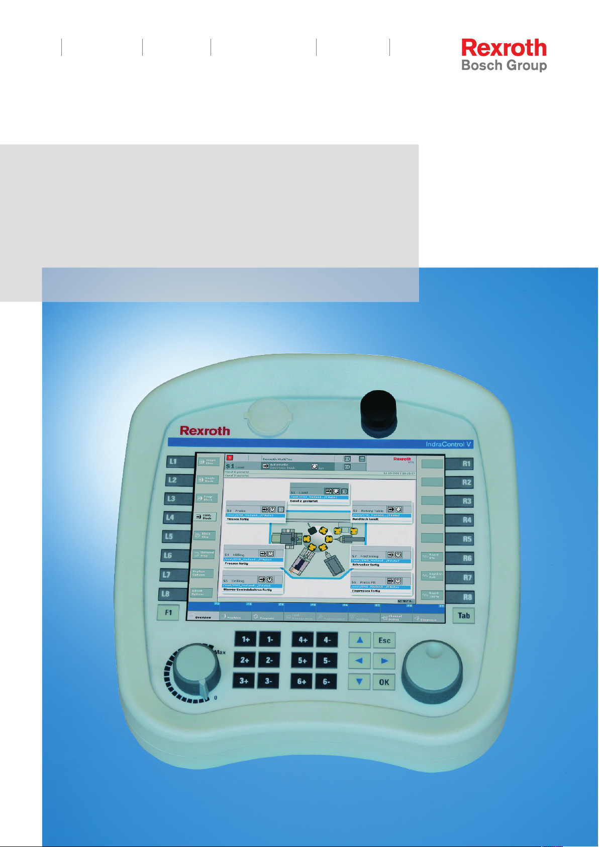
The IndraControl VEH 30.2 Hand-Held Terminal is a portable, PC-based op‐
erator and visualization device.
The 2-circuit, 3-stage enabling device as well as the 2-circuit stop pushbutton
ensure a safe operation of the IndraLogic and IndraMotion controls. The
IndraControl VEH 30.2 facilitates the comfortable configuration of machines
and installations located at widely distributed connection points.
All device variants feature a 213.36 (8.4") TFT display with always eight func‐
tion keys at the right side and left side of the screen as well as jog keys for up
to six axes for comfortable operation of the system. Additionally, service inter‐
faces are available: a USB connector on the front panel and an Ethernet in‐
terface on the VAC 30.2 connection module. Different cable variants allow an
individual adjustment to the conditions. The following table lists the most im‐
portant features of the IndraControl VEH 30.2. Differences between the de‐
vice variants are listed in chapter 1.2 "Device Variants" on page 5.
Bosch Rexroth AG 5/109
System Presentation
Display 213.36 mm TFT (8.4")
Keys Yes
Touch screen Yes
Enabling device 2-circuit, 3-stage
Stop button 2-circuit
Interface Ethernet
Service interface USB interface on the front
Connection IndraControl VAC 30.2 with stop pushbutton
jumpering
Additional options Handwheel, 16-stage automatic override, availa‐
ble depending on the device variant (see tab. 1-2
"Device variants IndraControl VEH 30.2" on page
6)
Tab.1-1: Main features IndraControl VEH 30.2
The IndraControl VEH 30.2 is suitable for the following application ranges:
● Operating and visualizing Bosch Rexroth control systems.
● Configuration of machines and installations.
● Operation and diagnostics of extended handling installations.
● Remote visualization of operating panels.
● Visualization of simple operating fields and assembly lines.
1.2 Device Variants
The IndraControl VEH 30.2 Hand-Held Terminals are available in different
variants.
The specifications about the IndraControl VEH 30 devices made
in the documentation "Rexroth IndraControl VEP/VEH" DOKSUPPL*-VEP/VEH*****-PR01-EN-P are obsolete.

6/109
Bosch Rexroth AG DOK-SUPPL*-VEH*30.2***-PR03-EN-P
System Presentation
Rexroth IndraControl VEH 30.2 Hand-Held Terminal
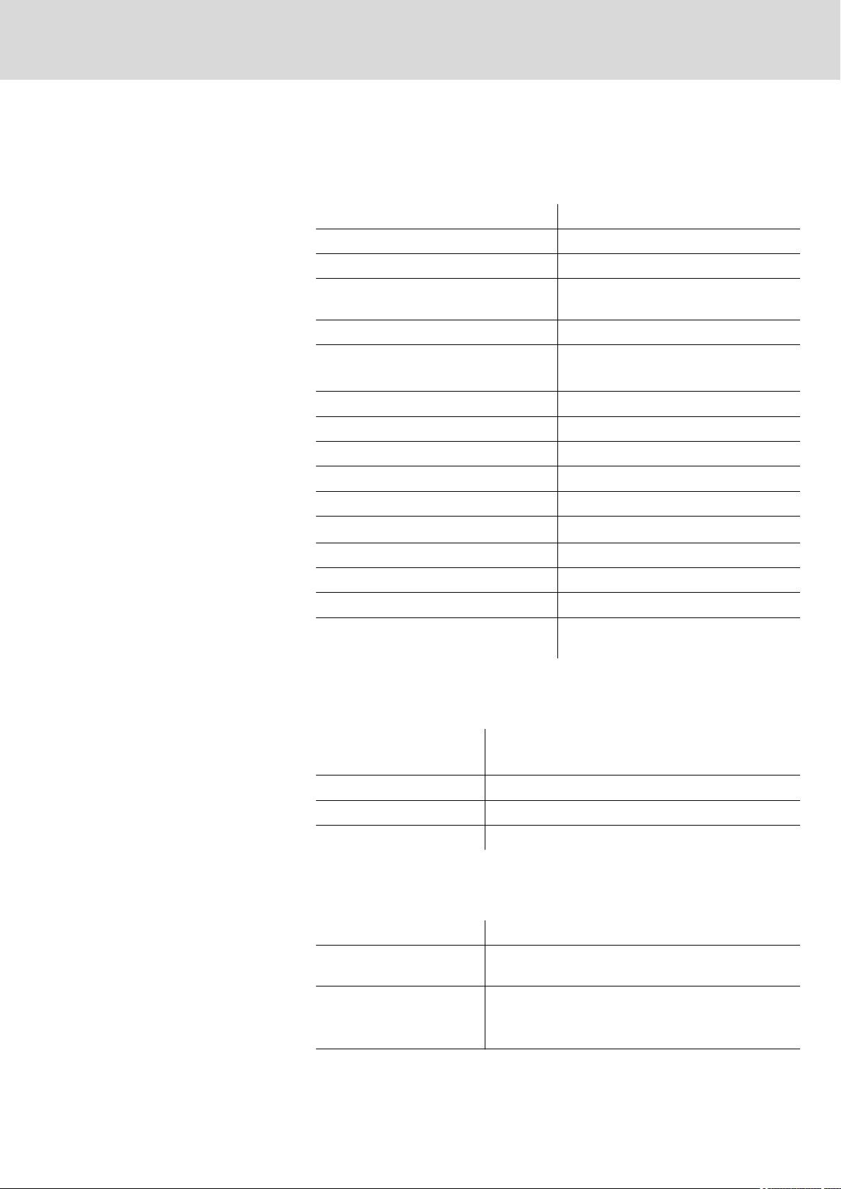
1.3 Housing
Device Optional elements,
characteristics
VEH30.2BNN-512ETA2D-4G0-BS-E4-FW
VEH30.2BNN-512ETA2D-4G0-DS-E4-FW
VEH30.2BNN-512ETA2D-4G0-DS-E2-FW
VEH30.2BNN-512ETA2D-4G0-BS-E2-FW
Tab.1-2: Device variants IndraControl VEH 30.2
Handwheel
Override
Handwheel
Override
Short extension ca‐
ble
Short extension ca‐
ble
Safety Parts number
Stop button,
Enabling device
Stop button,
Enabling device
Stop button,
Enabling device
Stop button,
Enabling device
R911172223
R911171948
R911172224
R911172162
For further information on "Selection of technical safety", please refer to the
sections on the new Machinery Directive in chapter 4 "Technical Data" on
page 25.
The vibration and shock resistant housing consists of low-inflammable mate‐
rial (UL 94-V2). The housing is resistant to impact, water, detergents (alcohol
and tensides), oil, cutting oil (drilling oil), grease, and lubricants. The robust
housing was tested on free fall onto industrial floor (height 1 m) in terms of
the environmental compatibility tests according to DIN EN 61131.
1.4 Membrane Keyboard
The foil keyboard consists of a chemical resistant polyester foil with em‐
bossed keys.
1.5 Touch screen
The front panel with touch screen allows you to operate the application soft‐
ware via the touch-sensitive surface of the display without keyboard and
mouse.
DOK-SUPPL*-VEH*30.2***-PR03-EN-P
Rexroth IndraControl VEH 30.2 Hand-Held Terminal
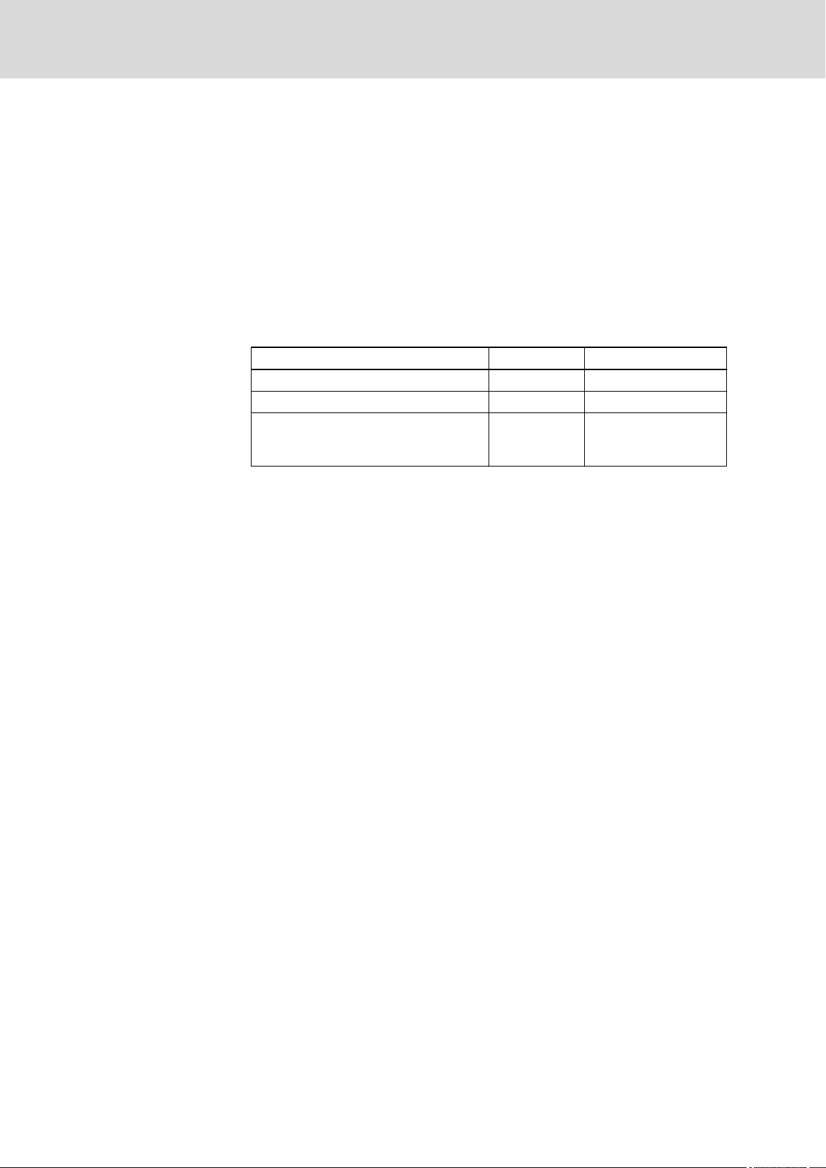
1.6 Front Panel of the IndraControl VEH 30.2
Bosch Rexroth AG 7/109
System Presentation
① USB connection
② Stop button
③ Membrane Keyboard
④ Display
⑤ Installation point for override
⑥ Installation point for electronic handwheel
Fig.1-1: Front view of the IndraControl VEH 30.2
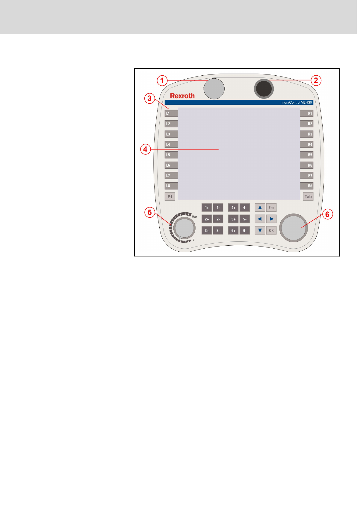
1.7 Connection to the Control
The IndraControl VEH 30.2 hand-held terminal is connected to the control via
the IndraControl VAC 30.2 connection module. At the front side a 17-pin fe‐
male connector allows the comfortable connection of a
IndraControl VEH 30.2. All clamps for fix wiring to the control are located on
the rear side of the connection module in the control cabinet.
The VAC 30.2 connection module is suitable for hand-held terminals with
stop pushbutton. The connection module is equipped with a fine thread
screwed plug on the front side. The integrated "automatic stop button jumper‐
ing" allows to integrate both channels of the stop button of the hand-held ter‐
minal into the safety circuit of the running machine without accidental shut‐
down of the machine.
NOTICE
8/109
System Presentation
Bosch Rexroth AG DOK-SUPPL*-VEH*30.2***-PR03-EN-P
Rexroth IndraControl VEH 30.2 Hand-Held Terminal
Fig.1-2: Front view: IndraControl VAC 30.2
1.8 Operating System
For license reasons IndraControl VEH 30.2 are only delivered with already in‐
stalled operating system. For further information about the operating system
please refer to chapter 9 "Software" on page 83.
1.9 Commissioning
Please mount the IndraControl VAC 30.2 connection module according to the
specifications in chapter 5 "Dimensions" on page 51. After this connect the
connection module to the following components:
● Voltage supply
● Stop circuit
● Enabling circuit
● Network
Before commissioning the IndraControl VEH 30.2 the operator has to assure
that the plant, especially the safety devices, are in a proper state.
Shutdown of the plant due to the connection
of a IndraControl VEH 30.2 with pressed stop
pushbutton.
Before commissioning the IndraControl VEH 30.2 do observe that the stop
pushbutton is not pressed.
For connecting the IndraControl VEH 30.2 put the connector without effort to
the flange of the VAC 30.2 connection module. Observe the latch position of

NOTICE
DOK-SUPPL*-VEH*30.2***-PR03-EN-P
Rexroth IndraControl VEH 30.2 Hand-Held Terminal
the connection. Connecting cables with a production date before 2011 with
an angled plug, are fitted in a 45° angle to the horizontal. Only if the connec‐
tor snaps in properly, the correct position is reached. Now turn the knurled
nut with slight pressure on the flange.
While the connector is screwed on a VAC 30.2 connection module, a relay
activates the stop button. In this way the IndraControl VEH 30.2 is supplied
with voltage. Screw the knurled nut as far as the rubber seal is completely
covered and the end position is reached to ensure the optimal connection of
the contacts and to achieve the specified degree of protection.
Verify all three positions of the enabling button from both sides for correct
function during commissioning of the IndraControl VEH 30.2 and regularly
during routine operation.
Verify the stop pushbutton for correct function in safe state of the plant of the
IndraControl VEH 30.2 in regular intervals and during commissioning.
The device may only be commissioned and connected by qualified staff.
Find further details about commissioning in the documentation of the device
or installation manufacturer.
Bosch Rexroth AG 9/109
System Presentation
Loss of specified degree of protection due to
incorrect connection of contacts.

10/109
Bosch Rexroth AG DOK-SUPPL*-VEH*30.2***-PR03-EN-P
Rexroth IndraControl VEH 30.2 Hand-Held Terminal

DOK-SUPPL*-VEH*30.2***-PR03-EN-P
Rexroth IndraControl VEH 30.2 Hand-Held Terminal
Important Instructions on Use, Target Group and Purpose of the Document
Bosch Rexroth AG 11/109
2 Important Instructions on Use, Target Group and Pur‐
pose of the Document
2.1 General Information
Read this chapter as well as chapter 3 "Safety Instructions for Electric Drives
and Controls" on page 15 before taking the product into operation – read
the information carefully. For any questions, please contact your sales repre‐
sentative or the Bosch Rexroth Support, see chapter 12 "Service and Sup‐
port" on page 101.
This document contains all specifications required by machinery directive
2006/42/EC.
In terms of the machinery, the present project planning manual
serves as assembly instructions.
2.2 Purpose of the Document
This documentation describes the IndraControl VEH 30.2 Hand-Held Termi‐
nals .
2.3 Target Group, Preconditions
This document is intended for the following persons with corresponding pre‐
conditions:
WARNING
12/109
Bosch Rexroth AG DOK-SUPPL*-VEH*30.2***-PR03-EN-P
Rexroth IndraControl VEH 30.2 Hand-Held Terminal
Important Instructions on Use, Target Group and Purpose of the Document
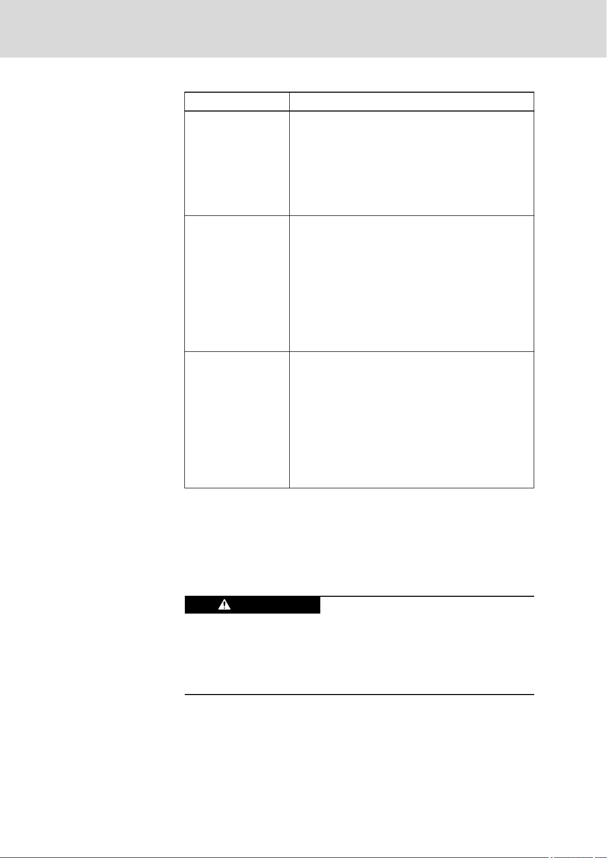
Target group Prerequisite knowledge and ability
Project engineer Technical basic education (advanced technical education,
engineering degree or corresponding professional experi‐
ence),
Knowledge about:
● the method of operation of a PLC
● safety regulations
● the application
Start-up technician Technical basic education (advanced technical education,
engineering degree or corresponding professional experi‐
ence),
Knowledge about:
● safety regulations
● the method of operation of the machine or system
● fundamental functions of the application
● system analysis and troubleshooting
● the setting options at the operating devices
Service technician Technical basic education (advanced technical education,
Tab.2-1: Target group, prerequisites
2.4 Appropriate Use
2.4.1 Introduction
Rexroth products represent state-of-the-art developments and manufacturing.
They are tested prior to delivery to ensure operational safety and reliability.
The products are designed for the use in an industrial environment and may
therefore only be used for the appropriate use. If they are not used appropri‐
ately, situations causing personal injury as well as material damage can oc‐
cur.
engineering degree or corresponding professional experi‐
ence),
Knowledge about:
● the method of operation of a PLC
● safety regulations
● the method of operation of the machine or system
● diagnostic configurations
● systematic error analysis and troubleshooting
Physical injury and material damage might
result from an inappropriate use of the prod‐
ucts!

NOTICE
DOK-SUPPL*-VEH*30.2***-PR03-EN-P
Rexroth IndraControl VEH 30.2 Hand-Held Terminal
Important Instructions on Use, Target Group and Purpose of the Document
Before using Bosch Rexroth products, the following requirements must be
met to ensure appropriate use of the products:
● Anyone handling one of the Rexroth products in any way has to read
and understand the respective safety-related guidelines as well as the
instructions on appropriate use.
● Hardware products have to remain in their original state, i. e. no modifi‐
cation regarding the design is allowed. Software products must not be
decompiled and their source codes must not be modified.
● Damaged or faulty products must not be implemented or put into opera‐
tion.
● It must be ensured that the products are installed as specified in the
documentation.
Bosch Rexroth AG 13/109
Bosch Rexroth disclaims as manufacturer any warranty, liability or
damages occurring due to inappropriate use of the products. Fur‐
thermore, Bosch Rexroth is not paying any compensation; the
user is responsible for any risks resulting from inappropriate use
of the products.
2.4.2 Areas of Use and Application
The IndraControl VEH 30.2 Hand-Held Terminal is a PC-based operating and
visualization device that can also fulfill control functionalities, depending on
the application or configuration.
The IndraControl VEH 30.2 Hand-Held Terminals may exclusively be used
with the accessories and add-on components specified in this documentation.
Components not named expressly mentioned must neither be mounted nor
connected. The same applies to cables and conduits.
The products may only be operated with the expressly stated configurations
and component combinations as well as with the software and firmware
which given and specified in the respective functional description.
The IndraControl VEH 30.2 Hand-Held Terminal was developed for control
tasks.
Typical areas of application of the IndraControl VEH 30.2 Hand-Held Termi‐
nal are:
● Handling systems and assembly systems
● Packaging and food processing machines
● Printing machines and paper converting machines
● Machine tools
The devices of the IndraControl VEH 30.2 design may only be operated un‐
der the assembly conditions and installation conditions, in the specified posi‐
tion of application and under the specified ambient conditions (temperature,
degree of protection, humidity, EMC etc.) given in this documentation.
Danger of destruction of the device if not ex‐
pressly stated accessories, add-on compo‐
nents and other components, cables, con‐
duits, software and firmware is used.

14/109
Important Instructions on Use, Target Group and Purpose of the Document
Bosch Rexroth AG DOK-SUPPL*-VEH*30.2***-PR03-EN-P
Rexroth IndraControl VEH 30.2 Hand-Held Terminal
2.5 Inappropriate Use
The application of IndraControl VEH 30.2 Hand-Held Terminals that are not
within the specified areas of application or under operating conditions deviat‐
ing from the operating conditions and technical data specified in the docu‐
mentation is considered as "inappropriate".
IndraControl VEH 30.2 Hand-Held Terminal must not be used if
● it is exposed to operating conditions that do not fulfill the ambient condi‐
tions specified. For instance, operation under water, in case of extreme
variations of temperature or in extreme maximum temperatures is not al‐
lowed.
● Bosch Rexroth has not explicitly released the intended applications. It is
imperative that you also note the information given in the general notes
on safety!

DOK-SUPPL*-VEH*30.2***-PR03-EN-P
Rexroth IndraControl VEH 30.2 Hand-Held Terminal
Bosch Rexroth AG 15/109
Safety Instructions for Electric Drives and Controls
3 Safety Instructions for Electric Drives and Controls
3.1 Definitions of Terms
Application Documentation
Component
Control System
Device
Electrical Equipment
Electric Drive System
Installation
Machine
Manufacturer
Product
Project Planning Manual
Qualified Persons
Application documentation comprises the entire documentation used to in‐
form the user of the product about the use and safety-relevant features for
configuring, integrating, installing, mounting, commissioning, operating, main‐
taining, repairing and decommissioning the product. The following terms are
also used for this kind of documentation: Operating Instructions, Commis‐
sioning Manual, Instruction Manual, Project Planning Manual, Application De‐
scription, etc.
A component is a combination of elements with a specified function, which
are part of a piece of equipment, device or system. Components of the elec‐
tric drive and control system are, for example, supply units, drive controllers,
mains choke, mains filter, motors, cables, etc.
A control system comprises several interconnected control components
placed on the market as a single functional unit.
A device is a finished product with a defined function, intended for users and
placed on the market as an individual piece of merchandise.
Electrical equipment encompasses all devices used to generate, convert,
transmit, distribute or apply electrical energy, such as electric motors, trans‐
formers, switching devices, cables, lines, power-consuming devices, circuit
board assemblies, plug-in units, control cabinets, etc.
An electric drive system comprises all components from mains supply to mo‐
tor shaft; this includes, for example, electric motor(s), motor encoder(s), sup‐
ply units and drive controllers, as well as auxiliary and additional compo‐
nents, such as mains filter, mains choke and the corresponding lines and ca‐
bles.
An installation consists of several devices or systems interconnected for a
defined purpose and on a defined site which, however, are not intended to be
placed on the market as a single functional unit.
A machine is the entirety of interconnected parts or units at least one of
which is movable. Thus, a machine consists of the appropriate machine drive
elements, as well as control and power circuits, which have been assembled
for a specific application. A machine is, for example, intended for processing,
treatment, movement or packaging of a material. The term "machine" also
covers a combination of machines which are arranged and controlled in such
a way that they function as a unified whole.
The manufacturer is an individual or legal entity bearing responsibility for the
design and manufacture of a product which is placed on the market in the in‐
dividual's or legal entity's name. The manufacturer can use finished products,
finished parts or finished elements, or contract out work to subcontractors.
However, the manufacturer must always have overall control and possess
the required authority to take responsibility for the product.
Examples of a product: Device, component, part, system, software, firmware,
among other things.
A project planning manual is part of the application documentation used to
support the sizing and planning of systems, machines or installations.
In terms of this application documentation, qualified persons are those per‐
sons who are familiar with the installation, mounting, commissioning and op‐
eration of the components of the electric drive and control system, as well as
with the hazards this implies, and who possess the qualifications their work

16/109
Safety Instructions for Electric Drives and Controls
Bosch Rexroth AG DOK-SUPPL*-VEH*30.2***-PR03-EN-P
Rexroth IndraControl VEH 30.2 Hand-Held Terminal
requires. To comply with these qualifications, it is necessary, among other
things,
1) to be trained, instructed or authorized to switch electric circuits and devi‐
ces safely on and off, to ground them and to mark them
2) to be trained or instructed to maintain and use adequate safety equipment
3) to attend a course of instruction in first aid
User
A user is a person installing, commissioning or using a product which has
been placed on the market.
3.2 General Information
3.2.1 Using the Safety Instructions and Passing Them on to Others
Do not attempt to install and operate the components of the electric drive and
control system without first reading all documentation provided with the prod‐
uct. Read and understand these safety instructions and all user documenta‐
tion prior to working with these components. If you do not have the user doc‐
umentation for the components, contact your responsible Bosch Rexroth
sales partner. Ask for these documents to be sent immediately to the person
or persons responsible for the safe operation of the components.
If the component is resold, rented and/or passed on to others in any other
form, these safety instructions must be delivered with the component in the
official language of the user's country.
Improper use of these components, failure to follow the safety instructions in
this document or tampering with the product, including disabling of safety de‐
vices, could result in property damage, injury, electric shock or even death.
3.2.2 Requirements for Safe Use
Read the following instructions before initial commissioning of the compo‐
nents of the electric drive and control system in order to eliminate the risk of
injury and/or property damage. You must follow these safety instructions.
● Bosch Rexroth is not liable for damages resulting from failure to observe
the safety instructions.
● Read the operating, maintenance and safety instructions in your lan‐
guage before commissioning. If you find that you cannot completely un‐
derstand the application documentation in the available language,
please ask your supplier to clarify.
● Proper and correct transport, storage, mounting and installation, as well
as care in operation and maintenance, are prerequisites for optimal and
safe operation of the component.
● Only qualified persons may work with components of the electric drive
and control system or within its proximity.
● Only use accessories and spare parts approved by Bosch Rexroth.
● Follow the safety regulations and requirements of the country in which
the components of the electric drive and control system are operated.
● Only use the components of the electric drive and control system in the
manner that is defined as appropriate. See chapter "Appropriate Use".
● The ambient and operating conditions given in the available application
documentation must be observed.
● Applications for functional safety are only allowed if clearly and explicitly
specified in the application documentation "Integrated Safety Technolo‐

DOK-SUPPL*-VEH*30.2***-PR03-EN-P
Rexroth IndraControl VEH 30.2 Hand-Held Terminal
gy". If this is not the case, they are excluded. Functional safety is a safe‐
ty concept in which measures of risk reduction for personal safety de‐
pend on electrical, electronic or programmable control systems.
● The information given in the application documentation with regard to
the use of the delivered components contains only examples of applica‐
tions and suggestions.
The machine and installation manufacturers must
– make sure that the delivered components are suited for their indi‐
vidual application and check the information given in this applica‐
tion documentation with regard to the use of the components,
– make sure that their individual application complies with the appli‐
cable safety regulations and standards and carry out the required
measures, modifications and complements.
● Commissioning of the delivered components is only allowed once it is
sure that the machine or installation in which the components are instal‐
led complies with the national regulations, safety specifications and
standards of the application.
● Operation is only allowed if the national EMC regulations for the applica‐
tion are met.
● The instructions for installation in accordance with EMC requirements
can be found in the section on EMC in the respective application docu‐
mentation.
The machine or installation manufacturer is responsible for compliance
with the limit values as prescribed in the national regulations.
● The technical data, connection and installation conditions of the compo‐
nents are specified in the respective application documentations and
must be followed at all times.
National regulations which the user must take into account
● European countries: In accordance with European EN standards
● United States of America (USA):
– National Electrical Code (NEC)
– National Electrical Manufacturers Association (NEMA), as well as
local engineering regulations
– Regulations of the National Fire Protection Association (NFPA)
● Canada: Canadian Standards Association (CSA)
● Other countries:
– International Organization for Standardization (ISO)
– International Electrotechnical Commission (IEC)
Bosch Rexroth AG 17/109
Safety Instructions for Electric Drives and Controls
3.2.3 Hazards by Improper Use
● High electrical voltage and high working current! Danger to life or seri‐
ous injury by electric shock!
● High electrical voltage by incorrect connection! Danger to life or injury by
electric shock!
● Dangerous movements! Danger to life, serious injury or property dam‐
age by unintended motor movements!
● Health hazard for persons with heart pacemakers, metal implants and
hearing aids in proximity to electric drive systems!

18/109
Safety Instructions for Electric Drives and Controls
Bosch Rexroth AG DOK-SUPPL*-VEH*30.2***-PR03-EN-P
Rexroth IndraControl VEH 30.2 Hand-Held Terminal
● Risk of burns by hot housing surfaces!
● Risk of injury by improper handling! Injury by crushing, shearing, cutting,
hitting!
● Risk of injury by improper handling of batteries!
● Risk of injury by improper handling of pressurized lines!
3.3 Instructions with Regard to Specific Dangers
3.3.1 Protection Against Contact with Electrical Parts and Housings
This section concerns components of the electric drive and con‐
trol system with voltages of more than 50 volts.
Contact with parts conducting voltages above 50 volts can cause personal
danger and electric shock. When operating components of the electric drive
and control system, it is unavoidable that some parts of these components
conduct dangerous voltage.
High electrical voltage! Danger to life, risk of injury by electric shock or seri‐
ous injury!
● Only qualified persons are allowed to operate, maintain and/or repair the
components of the electric drive and control system.
● Follow the general installation and safety regulations when working on
power installations.
● Before switching on, the equipment grounding conductor must have
been permanently connected to all electric components in accordance
with the connection diagram.
● Even for brief measurements or tests, operation is only allowed if the
equipment grounding conductor has been permanently connected to the
points of the components provided for this purpose.
● Before accessing electrical parts with voltage potentials higher than
50 V, you must disconnect electric components from the mains or from
the power supply unit. Secure the electric component from reconnec‐
tion.
● With electric components, observe the following aspects:
Always wait 30 minutes after switching off power to allow live capacitors
to discharge before accessing an electric component. Measure the elec‐
trical voltage of live parts before beginning to work to make sure that the
equipment is safe to touch.
● Install the covers and guards provided for this purpose before switching
on.
● Never touch electrical connection points of the components while power
is turned on.
● Do not remove or plug in connectors when the component has been
powered.
● Under specific conditions, electric drive systems can be operated at
mains protected by residual-current-operated circuit-breakers sensitive
to universal current (RCDs/RCMs).

DOK-SUPPL*-VEH*30.2***-PR03-EN-P
Rexroth IndraControl VEH 30.2 Hand-Held Terminal
● Secure built-in devices from penetrating foreign objects and water, as
well as from direct contact, by providing an external housing, for exam‐
ple a control cabinet.
High housing voltage and high leakage current! Danger to life, risk of injury
by electric shock!
● Before switching on and before commissioning, ground or connect the
components of the electric drive and control system to the equipment
grounding conductor at the grounding points.
● Connect the equipment grounding conductor of the components of the
electric drive and control system permanently to the main power supply
at all times. The leakage current is greater than 3.5 mA.
● Establish an equipment grounding connection with a minimum cross
section according to the table below. With an outer conductor cross sec‐
tion smaller than 10 mm2 (8 AWG), the alternative connection of two
equipment grounding conductors is allowed, each having the same
cross section as the outer conductors.
Bosch Rexroth AG 19/109
Safety Instructions for Electric Drives and Controls
Cross section outer con‐
ductor
1.5 mm2 (16 AWG)
2.5 mm2 (14 AWG) 2 × 2.5 mm2 (14 AWG)
4 mm2 (12 AWG) 2 × 4 mm2 (12 AWG)
6 mm2 (10 AWG) 2 × 6 mm2 (10 AWG)
10 mm2 (8 AWG)
16 mm2 (6 AWG)
25 mm2 (4 AWG)
35 mm2 (2 AWG)
50 mm2 (1/0 AWG) 25 mm2 (4 AWG)
70 mm2 (2/0 AWG) 35 mm2 (2 AWG)
... ... ...
Tab.3-1: Minimum Cross Section of the Equipment Grounding Connection
Minimum cross section equipment grounding conductor
Leakage current ≥ 3.5 mA
1 equipment grounding
conductor
10 mm2 (8 AWG)
16 mm2 (6 AWG)
2 equipment grounding
conductors
2 × 1.5 mm2 (16 AWG)
-
-
-
-
-
-
3.3.2 Protective Extra-Low Voltage as Protection Against Electric Shock
Protective extra-low voltage is used to allow connecting devices with basic in‐
sulation to extra-low voltage circuits.
On components of an electric drive and control system provided by Bosch
Rexroth, all connections and terminals with voltages up to 50 volts are PELV
("Protective Extra-Low Voltage") systems. It is allowed to connect devices
equipped with basic insulation (such as programming devices, PCs, note‐
books, display units) to these connections.

20/109
Safety Instructions for Electric Drives and Controls
Bosch Rexroth AG DOK-SUPPL*-VEH*30.2***-PR03-EN-P
Rexroth IndraControl VEH 30.2 Hand-Held Terminal
Danger to life, risk of injury by electric shock! High electrical voltage by incor‐
rect connection!
If extra-low voltage circuits of devices containing voltages and circuits of
more than 50 volts (e.g., the mains connection) are connected to Bosch
Rexroth products, the connected extra-low voltage circuits must comply with
the requirements for PELV ("Protective Extra-Low Voltage").
3.3.3 Protection Against Dangerous Movements
Dangerous movements can be caused by faulty control of connected motors.
Some common examples are:
● Improper or wrong wiring or cable connection
● Operator errors
● Wrong input of parameters before commissioning
● Malfunction of sensors and encoders
● Defective components
● Software or firmware errors
These errors can occur immediately after equipment is switched on or even
after an unspecified time of trouble-free operation.
The monitoring functions in the components of the electric drive and control
system will normally be sufficient to avoid malfunction in the connected
drives. Regarding personal safety, especially the danger of injury and/or
property damage, this alone cannot be relied upon to ensure complete safety.
Until the integrated monitoring functions become effective, it must be as‐
sumed in any case that faulty drive movements will occur. The extent of faulty
drive movements depends upon the type of control and the state of opera‐
tion.
Dangerous movements! Danger to life, risk of injury, serious injury or property
damage!
A risk assessment must be prepared for the installation or machine, with its
specific conditions, in which the components of the electric drive and control
system are installed.
As a result of the risk assessment, the user must provide for monitoring func‐
tions and higher-level measures on the installation side for personal safety.
The safety regulations applicable to the installation or machine must be taken
into consideration. Unintended machine movements or other malfunctions
are possible if safety devices are disabled, bypassed or not activated.
To avoid accidents, injury and/or property damage:
● Keep free and clear of the machine’s range of motion and moving ma‐
chine parts. Prevent personnel from accidentally entering the machine’s
range of motion by using, for example:
– Safety fences
– Safety guards
– Protective coverings
– Light barriers
● Make sure the safety fences and protective coverings are strong enough
to resist maximum possible kinetic energy.
● Mount emergency stopping switches in the immediate reach of the oper‐
ator. Before commissioning, verify that the emergency stopping equip‐

DOK-SUPPL*-VEH*30.2***-PR03-EN-P
Rexroth IndraControl VEH 30.2 Hand-Held Terminal
ment works. Do not operate the machine if the emergency stopping
switch is not working.
● Prevent unintended start-up. Isolate the drive power connection by
means of OFF switches/OFF buttons or use a safe starting lockout.
● Make sure that the drives are brought to safe standstill before accessing
or entering the danger zone.
● Additionally secure vertical axes against falling or dropping after switch‐
ing off the motor power by, for example,
– mechanically securing the vertical axes,
– adding an external braking/arrester/clamping mechanism or
– ensuring sufficient counterbalancing of the vertical axes.
● The standard equipment motor holding brake or an external holding
brake controlled by the drive controller is not sufficient to guarantee per‐
sonal safety!
● Disconnect electrical power to the components of the electric drive and
control system using the master switch and secure them from reconnec‐
tion ("lock out") for:
– Maintenance and repair work
– Cleaning of equipment
– Long periods of discontinued equipment use
● Prevent the operation of high-frequency, remote control and radio equip‐
ment near components of the electric drive and control system and their
supply leads. If the use of these devices cannot be avoided, check the
machine or installation, at initial commissioning of the electric drive and
control system, for possible malfunctions when operating such high-fre‐
quency, remote control and radio equipment in its possible positions of
normal use. It might possibly be necessary to perform a special electro‐
magnetic compatibility (EMC) test.
Bosch Rexroth AG 21/109
Safety Instructions for Electric Drives and Controls
3.3.4 Protection Against Magnetic and Electromagnetic Fields During Oper‐
ation and Mounting
Magnetic and electromagnetic fields generated by current-carrying conduc‐
tors or permanent magnets of electric motors represent a serious danger to
persons with heart pacemakers, metal implants and hearing aids.
Health hazard for persons with heart pacemakers, metal implants and hear‐
ing aids in proximity to electric components!
● Persons with heart pacemakers and metal implants are not allowed to
enter the following areas:
– Areas in which components of the electric drive and control sys‐
tems are mounted, commissioned and operated.
– Areas in which parts of motors with permanent magnets are stored,
repaired or mounted.
● If it is necessary for somebody with a heart pacemaker to enter such an
area, a doctor must be consulted prior to doing so. The noise immunity
of implanted heart pacemakers differs so greatly that no general rules
can be given.
● Those with metal implants or metal pieces, as well as with hearing aids,
must consult a doctor before they enter the areas described above.

22/109
Safety Instructions for Electric Drives and Controls
Bosch Rexroth AG DOK-SUPPL*-VEH*30.2***-PR03-EN-P
Rexroth IndraControl VEH 30.2 Hand-Held Terminal
3.3.5 Protection Against Contact with Hot Parts
Hot surfaces of components of the electric drive and control system. Risk of
burns!
● Do not touch hot surfaces of, for example, braking resistors, heat sinks,
supply units and drive controllers, motors, windings and laminated
cores!
● According to the operating conditions, temperatures of the surfaces can
be higher than 60 °C (140 °F) during or after operation.
● Before touching motors after having switched them off, let them cool
down for a sufficient period of time. Cooling down can require up to 140
minutes! The time required for cooling down is approximately five times
the thermal time constant specified in the technical data.
● After switching chokes, supply units and drive controllers off, wait 15 mi‐
nutes to allow them to cool down before touching them.
● Wear safety gloves or do not work at hot surfaces.
● For certain applications, and in accordance with the respective safety
regulations, the manufacturer of the machine or installation must take
measures to avoid injuries caused by burns in the final application.
These measures can be, for example: Warnings at the machine or in‐
stallation, guards (shieldings or barriers) or safety instructions in the ap‐
plication documentation.
3.3.6 Protection During Handling and Mounting
Risk of injury by improper handling! Injury by crushing, shearing, cutting, hit‐
ting!
● Observe the relevant statutory regulations of accident prevention.
● Use suitable equipment for mounting and transport.
● Avoid jamming and crushing by appropriate measures.
● Always use suitable tools. Use special tools if specified.
● Use lifting equipment and tools in the correct manner.
● Use suitable protective equipment (hard hat, safety goggles, safety
shoes, safety gloves, for example).
● Do not stand under hanging loads.
● Immediately clean up any spilled liquids from the floor due to the risk of
falling!
3.3.7 Battery Safety
Batteries consist of active chemicals in a solid housing. Therefore, improper
handling can cause injury or property damage.
Risk of injury by improper handling!
● Do not attempt to reactivate low batteries by heating or other methods
(risk of explosion and cauterization).
● Do not attempt to recharge the batteries as this may cause leakage or
explosion.
● Do not throw batteries into open flames.
● Do not dismantle batteries.

DANGER
DOK-SUPPL*-VEH*30.2***-PR03-EN-P
Rexroth IndraControl VEH 30.2 Hand-Held Terminal
Safety Instructions for Electric Drives and Controls
● When replacing the battery/batteries, do not damage the electrical parts
installed in the devices.
● Only use the battery types specified for the product.
Environmental protection and disposal! The batteries contained in
the product are considered dangerous goods during land, air, and
sea transport (risk of explosion) in the sense of the legal regula‐
tions. Dispose of used batteries separately from other waste. Ob‐
serve the national regulations of your country.
3.3.8 Protection Against Pressurized Systems
According to the information given in the Project Planning Manuals, motors
and components cooled with liquids and compressed air can be partially sup‐
plied with externally fed, pressurized media, such as compressed air, hy‐
draulics oil, cooling liquids and cooling lubricants. Improper handling of the
connected supply systems, supply lines or connections can cause injuries or
property damage.
Risk of injury by improper handling of pressurized lines!
● Do not attempt to disconnect, open or cut pressurized lines (risk of ex‐
plosion).
● Observe the respective manufacturer's operating instructions.
● Before dismounting lines, relieve pressure and empty medium.
● Use suitable protective equipment (safety goggles, safety shoes, safety
gloves, for example).
● Immediately clean up any spilled liquids from the floor due to the risk of
falling!
Bosch Rexroth AG 23/109
Environmental protection and disposal! The agents (e.g., fluids)
used to operate the product might not be environmentally friendly.
Dispose of agents harmful to the environment separately from
other waste. Observe the national regulations of your country.
3.4 Explanation of Signal Words and the Safety Alert Symbol
The Safety Instructions in the available application documentation contain
specific signal words (DANGER, WARNING, CAUTION or NOTICE) and,
where required, a safety alert symbol (in accordance with
ANSI Z535.6-2011).
The signal word is meant to draw the reader's attention to the safety instruc‐
tion and identifies the hazard severity.
The safety alert symbol (a triangle with an exclamation point), which pre‐
cedes the signal words DANGER, WARNING and CAUTION, is used to alert
the reader to personal injury hazards.
In case of non-compliance with this safety instruction, death or serious injury
will occur.

WARNING
CAUTION
NOTICE
24/109
Safety Instructions for Electric Drives and Controls
Bosch Rexroth AG DOK-SUPPL*-VEH*30.2***-PR03-EN-P
In case of non-compliance with this safety instruction, death or serious injury
could occur.
In case of non-compliance with this safety instruction, minor or moderate in‐
jury could occur.
In case of non-compliance with this safety instruction, property damage could
occur.
Rexroth IndraControl VEH 30.2 Hand-Held Terminal
DOK-SUPPL*-VEH*30.2***-PR03-EN-P
Rexroth IndraControl VEH 30.2 Hand-Held Terminal
4 Technical Data
4.1 IndraControl VEH 30.2
Processor Intel Atom processor Z510 (1.1 GHz)
RAM 512 MB
Flash onboard 4 GB
Interfaces 1 × Ethernet connection (RJ 45, 10/100
Service interface USB interface on the front
Further connections ● Stop button
Housing material Polyamide PA6, glass-fiber reinforced
Degree of protection IP 65, type 1 according to NEMA (UL)
Bosch Rexroth AG 25/109
Technical Data
base-T)
● Enabling device
4.2 Front Panel
Degree of pollution 3
Voltage supply DC 24 V
Input voltage range DC 24 V (+19 V to +30 V)
Emitted interference and surge immunity U
Max. input current 0.7 A for nominal voltage 24 V
Max. inrush current 3 A for nominal voltage 24 V
Prescribed external protection Fusible cut-out, 2 A time-lag
Max. power consumption for maximum
configuration
Tab.4-1: Technical data, IndraControl VEH 30.2
Display 213 mm TFT (8.4"), 1024 × 768 and 800 × 600 pixels
256k colors
Operation Touch and key operation with 40 keys
Surface front panel Color RAL 7035 light gray
Degree of protection Front panel IP 65 according to EN 60529, IEC 60529
= 35 V (for t < 100 ms)
max
14 W
Tab.4-2: Technical data, front panel of the IndraControl VEH 30.2
4.3 Stop Pushbutton
Design Stop button, black-gray, two-channels, isolated
Nominal voltage DC 24 V / AC 30 V protective extra low voltage
Nominal current 2 A = or 2.3 A~
(PELV)
Current carrying capacity of the output contacts is limi‐
ted by connected cable

26/109
Bosch Rexroth AG DOK-SUPPL*-VEH*30.2***-PR03-EN-P
Technical Data
Rexroth IndraControl VEH 30.2 Hand-Held Terminal
Prescribed external protec‐
tion
B10d value B10d: 250.000
Tab.4-3: Technical data, stop button
4.4 Enabling Device
Design
Nominal voltage DC 24 V / AC 30 V protective extra low voltage
Nominal current* 2 A = or 2.3 A~
Prescribed external protec‐
tion
Switching cycles >200000 for enabling range,
Control category Can be used in safety-related controls up to category
Fusible cut-out, 2 A time-lag
Exclusion of failure at <6050 switching cycles
3-stage enabling device
lated
(PELV)
Current carrying capacity of the output contacts is limi‐
ted by connected cable
Fusible cut-out, 2 A time-lag
>100000 for panic position
4, DIN EN 954-1 (if required with additional monitoring
modules).
Can be used in safety-related controls up to category
3 according to EN ISO 13849-1
1)
, 2-channel, electrically iso‐
B10d value B10d: 100.000
Tab.4-4: Technical data, enabling device
4.5 Connection Module IndraControl VAC 30.2
Connections ● 1 x Ethernet connection (RJ 45, 10/100 Base-T)
● Stop button
● Isolated contact "Terminal connected"
● Enabling device
● Voltage supply 24 V (see tab. 4-1 "Technical da‐
ta, IndraControl VEH 30.2" on page 25)
● 17-pin fine-thread flange to the hand-held termi‐
nal
Jumpering the stop pushbut‐
ton circuit with unplugged
hand-held terminal
Prescribed external protec‐
tion
Automatic jumpering of relay contacts
Fusible cut-out, 2 A time-lag
1)
Lines must be protected against short-circuits and cross-circuits by the installation!

DOK-SUPPL*-VEH*30.2***-PR03-EN-P
Rexroth IndraControl VEH 30.2 Hand-Held Terminal
Material Front panel: Aluminum, metal cover: V2A
Degree of protection Front panel IP 65,
Tab.4-5: Technical data, connection module IndraControl VAC 30.2
4.6 Ambient Conditions
In operation Storage Transport
Bosch Rexroth AG 27/109
Technical Data
Rear panel IP 30
Max. ambient tem‐
perature
+5 ℃ to 40 ℃ ac‐
cording to EN
50178, class 3K3
Max. temperature
gradient
Temporal tempera‐
ture changes up to
3 K per minute
Relative humidity Min. relative humid‐
ity: 10 %
Max. relative hu‐
midity: 95 %
Min. absolute hu‐
midity: 1 g/m
3
Max. absolute hu‐
midity: 25 g/m
3
Non-condensing
acc. to climatic
class 3K3 acc. to
EN 60721-3-3
Air pressure Up to 2,000 m
above sea level
acc. to EN 61131-2
Free fall Free fall from 1 m
height in the active
status, hazardous
impact
-20 ℃ to +70 ℃ ac‐
cording to EN
50178, class 3K3
Temporal tempera‐
ture changes up to
3 K per minute
Min. relative humid‐
ity: 5 %
Max. relative hu‐
midity: 95 %
Min. absolute hu‐
midity: 1 g/m
3
Max. absolute hu‐
midity: 25 g/m
3
Non-condensing
according to climat‐
ic class 2K2 acc. to
EN 60721-3-3
Up to 3000 m
above sea level
acc. to EN 61131-2
Free fall from a
height of 1 m, haz‐
ardous impact
-20 ℃ to +70 ℃ ac‐
cording to EN
50178, class 3K3
Temporal tempera‐
ture changes up to
3 K per minute
Min. relative humid‐
ity: 5 %
Max. relative hu‐
midity: 95 %
Min. absolute hu‐
midity: 1 g/m
3
Max. absolute hu‐
midity: 25 g/m
3
Non-condensing
acc. to climatic
class 1K2 acc. to
EN 60721-3-3
Up to 3000 m
above sea level
acc. to EN 61131-2
Free fall from a
height of 1 m, haz‐
ardous impact
Mechanical
strength
Max. vibration: Fre‐
quency range: 5 up
to 150 Hz
Excursion: 3.5 mm
amplitude at 5 to 9
Hz
Acceleration: 1 g
for 9 to 150 Hz
acc. to EN
60068-2-6
Max. shock: 15 g
11 ms acc. to EN
60068-2-27
No breakdown of
the function.
Three shocks in
each of the three
axes arranged ver‐
tically to each oth‐
er, always in both
directions (a total of
18 shocks)
Tab.4-6: Ambient conditions, IndraControl VEH 30.2
Max. shock: 15 g
11 ms acc. to EN
60068-2-27
No breakdown of
the function.
Three shocks in
each of the three
axes arranged ver‐
tically to each oth‐
er, always in both
directions (a total of
18 shocks)
28/109
Technical Data
Bosch Rexroth AG DOK-SUPPL*-VEH*30.2***-PR03-EN-P
4.7 Accessories
4.8 Marking
Rexroth IndraControl VEH 30.2 Hand-Held Terminal
Wall holder For stationary operation or for storage
VAS 01.1 Wall holder with cable holder
Connecting cable Torsional, bending and impact strength with ready-
made 17-pin round connector
VAS 05.1 0.5 m or 8 m
RKS0011/16,0 16 m extension cable for devices with stop pushbutton
Tab.4-7: Accessories for IndraControl VEH 30.2
For ordering information for the accessories, please refer to chapter 11.2
"Accessories" on page 98.
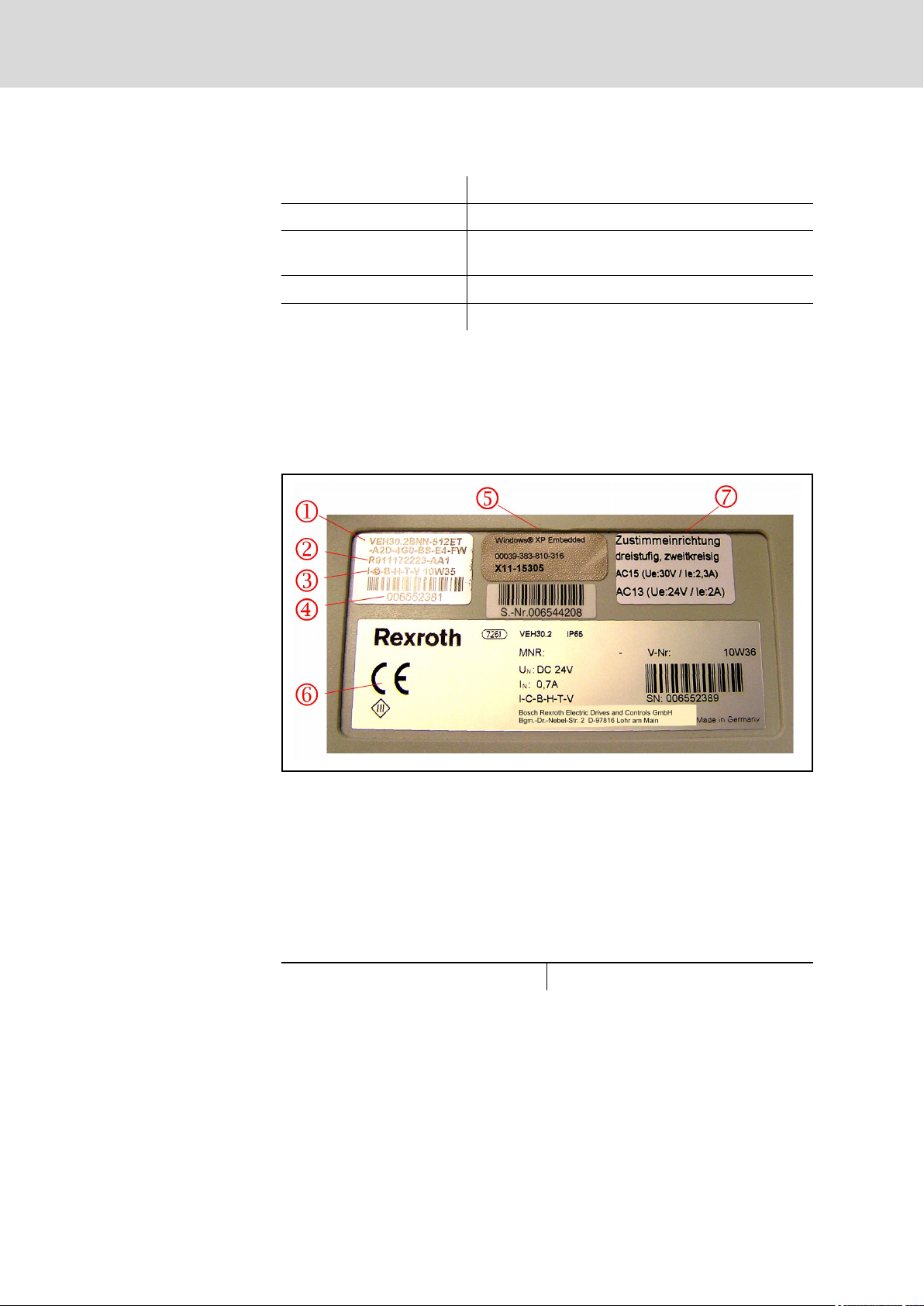
Identify the device with the type plate on the rear side of the device.
① Order code, short type
② Parts number
③ Production date, example 10W35: Production year 2010, week 35
④ Serial number, basic device
⑤ License and serial number of the operating system
⑥ Company logo, technical data, serial number of the basic device
⑦ Data of the enabling button
Fig.4-1: Type plate, IndraControl VEH 30.2
4.9 Weight
IndraControl VEH 30.2 Approx. 2.6 kg
Tab.4-8: Weight, IndraControl VEH 30.2
4.10 Used Standards
Enabling device and emergency
stop button
The present project planning manual complies with the Machinery Directive
2006/42/EC, see also chapter 4.12 "Further Information on the Machinery
Directive (MD)" on page 34. The terms used in the present project planning
manual are derived from the new Machinery Directive (MD) 2006/42/EC. In
 Loading...