

Bosch Rexroth IndraControl VDP 15.3, Rexroth IndraControl VDP 21.3, Rexroth IndraControl VDP 18.3 Operating Instructions Manual
Electr ic Drives
and Co ntrols Pneuma tics
Hydrau lics
Linear Motion and
Assemb ly Technolo gies
Servic e
Rexroth IndraControl
VDP 15.3, 18.3, 21.3 Multitouch
Operator Display – Built-In Devices
Operating Instructions
R911341191
Edition 02

Bosch Rexroth AG VDP 15.3, 18.3, 21.3 Multitouch
Record of Revision
Edition
Release Date Notes
First edition 10.2013 -Edition 02 03.2014 Revision
Copyright
© Bosch Rexroth AG 2014
This document, as well as the data, specifications and other information set
forth in it, are the exclusive property of Bosch Rexroth AG. It may not be reproduced or given to third parties without its consent.
Liability
The specified data is intended for product description purposes only and shall
not be deemed to be a guaranteed characteristic unless expressly stipulated in
the contract. All rights are reserved with respect to the content of this documentation and the availability of the product.
Editorial Department
Development Automation Aystems Control Hardware HB (KaWa/PiGe)
RS-efc79664d5c1106b0a6846a5001b631e-2-en-US-5

VDP 15.3, 18.3, 21.3 Multitouch Bosch Rexroth AG
Table of Contents
Table of Contents
Page
1 About this Documentation..................................................................... 1
2 Product Identification and Scope of Delivery........................................ 2
2.1 Product Identification............................................................................ 2
2.2 Scope of Delivery................................................................................... 3
3 Using the Safety Instructions................................................................. 3
3.1 Safety Instructions – Structure.............................................................. 3
3.2 Explaining Signal Words and Safety Alert Symbol................................. 4
3.3 Symbols Used........................................................................................ 5
4 Intended Use.......................................................................................... 5
5 Spare Parts, Accessories and Wear Parts.............................................. 6
5.1 Y-Repeater............................................................................................. 6
5.2 External 24 V Power Supply Unit .......................................................... 6
5.3 Uninterruptible Power Supply (UPS)..................................................... 6
5.4 Connecting Cables for the CDI Interface............................................... 6
5.5 Wear Parts............................................................................................. 7
6 Ambient Conditions............................................................................... 7
7 Technical Data....................................................................................... 9
7.1 General Technical Data.......................................................................... 9
7.2 Optical Characteristic Values................................................................. 9
7.2.1 TFT......................................................................................................... 9
7.2.2 Input System or Multitouch Front.......................................................... 9
8 Standards............................................................................................ 10
8.1 General Information............................................................................. 10
8.2 Used Standards................................................................................... 10
8.3 CE Marking........................................................................................... 10
8.3.1 Declaration of Conformity .................................................................. 10
8.4 UL/CSA Certified................................................................................. 11
9 Interfaces............................................................................................. 12
9.1 View..................................................................................................... 12
DOK-SUPPL*-VDPXX.3MTBU-IT02-EN-P
I

Bosch Rexroth AG
VDP 15.3, 18.3, 21.3 Multitouch
Table of Contents
Page
9.2 Overview.............................................................................................. 12
9.3 DC 24 V Voltage Supply....................................................................... 13
9.4 S1 DIP Switch...................................................................................... 13
9.4.1 Overview.............................................................................................. 13
9.5 USB Interfaces..................................................................................... 13
9.6 XSER Interfaces and XVID Interfaces................................................... 14
10 Assembly, Disassembly and Electrical Installation.............................. 15
10.1 Housing Dimensions............................................................................ 15
10.1.1 Rexroth Design.................................................................................... 15
10.1.2 Rexroth Special Design........................................................................ 16
10.1.3 Bosch Design....................................................................................... 17
10.2 Installation Notes................................................................................. 17
10.3 Assembly.............................................................................................. 17
10.4 VDP Assembly Dimensions................................................................... 20
10.5 Disassembly......................................................................................... 20
10.6 Electrical Wiring................................................................................... 21
10.6.1 Connecting the Control Cabinet PC to Operating Display................... 21
10.6.2 Connecting the OperatingDisplay to the 24 V Voltage Supply............. 23
10.6.3 Connection Scheme – Power Supply Unit, UPS, Control Cabinet PC
and Operating Display......................................................................... 24
10.6.4 Recommendation for the Assembly of CDI Cables with Long Lengths
in an Interference-Prone Environment................................................. 24
11 Commissioning.................................................................................... 27
12 Device Description............................................................................... 28
12.1 General Information............................................................................. 28
12.2 Operating and Error Display................................................................ 28
13 Error Causes and Elimination.............................................................. 28
14 Maintenance........................................................................................ 29
14.1 General Information............................................................................. 29
14.2 Display................................................................................................. 29
14.3 Cleaning Notes..................................................................................... 29
14.4 Regular Maintenance Tasks................................................................. 30
15 Ordering Information........................................................................... 30
II
DOK-SUPPL*-VDPXX.3MTBU-IT02-EN-P

VDP 15.3, 18.3, 21.3 Multitouch Bosch Rexroth AG
Table of Contents
Page
15.1 Accessories and Spare Parts............................................................... 30
15.2 Type Code............................................................................................ 31
16 Disposal............................................................................................... 31
16.1 Take-Back............................................................................................. 31
16.2 Packaging............................................................................................. 32
17 Service and Support............................................................................ 32
Index.................................................................................................... 35
DOK-SUPPL*-VDPXX.3MTBU-IT02-EN-P
III

Bosch Rexroth AG VDP 15.3, 18.3, 21.3 Multitouch
IV
DOK-SUPPL*-VDPXX.3MTBU-IT02-EN-P
Disposal company
Selection
Operation
Engineering
Commissioning
De-
commissioning
To test
To optimize
To create
the NC program
To remove
faults
To maintain
To operate
To simulate
To configure
To program
To parameterize
To install
To mount
To unpack
To construct
To design
To prepare
To select
Design engineer
Mechanic/
electrician)
Process
specialist
Machine
operator
Service
Presales Aftersales
Programmer
Technologist
Product
phases
Target
groups
Activities
Mounting
(assembly/installation)
Programmer
Mechanic/
electrician
To dismount
To dispose
Commissioning engineer
Technologist
Process specialist
Maintenance
technician
VDP 15.3, 18.3, 21.3 Multitouch
Bosch Rexroth AG
About this Documentation
1 About this Documentation
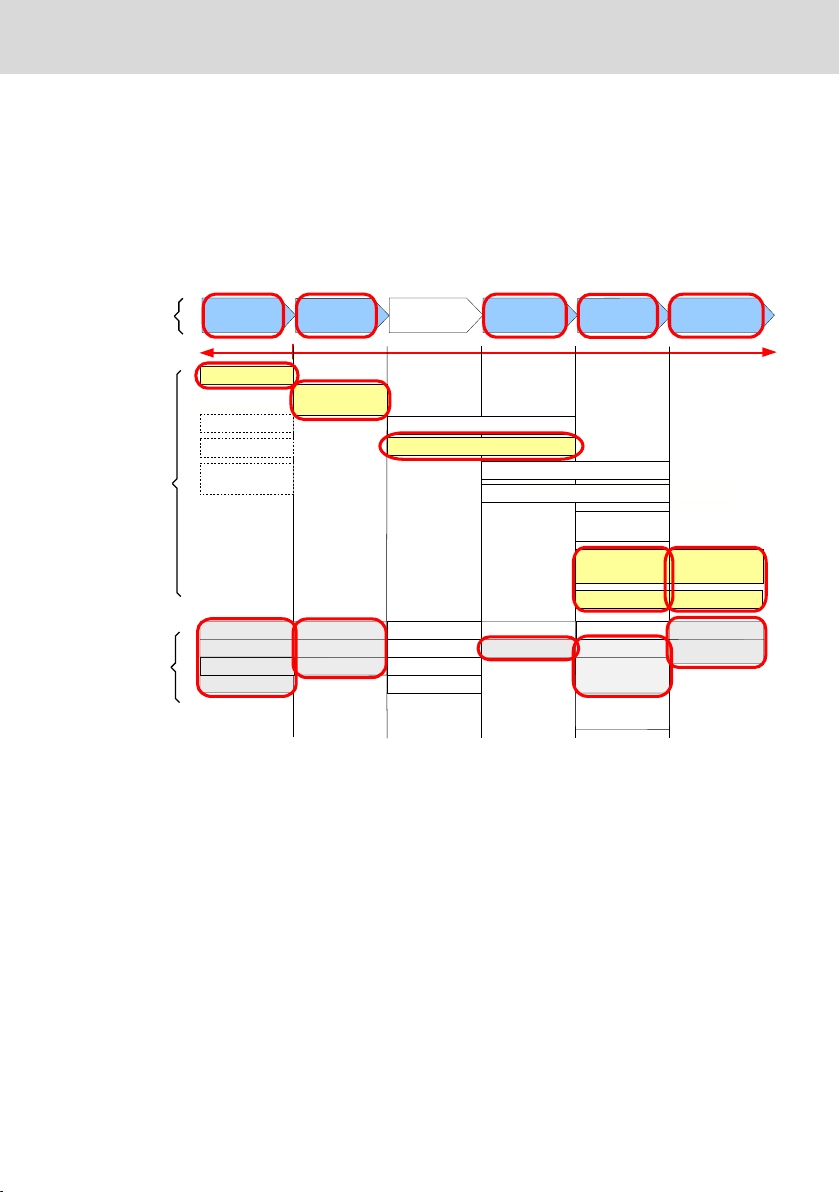
Overview – target groups and product phases
The activities, product phases and target groups that refer to the present docu-
mentation are marked in red color in the following figure.
Example: In the product phase "Mounting (assembly/installation)", the "mechan-
ic/electrician" can execute the activity "install" using this documentation.
Fig. 1-1: Assigning the present documentation to the target groups, product phases and activities of the target group
Purpose
This document instructs the technical staff of the machine manufacturer on how
to perform the mechanic and electrical installation in a safe way and on how to
commission the device.
Required qualifications: Individual who is able to assess the tasks assigned and
identify possible safety risks owing to qualification in the subject, knowledge
and experience. The individual should also be familiar with the standards and
regulations.
Scope
This operating instruction is valid for all multitouch operating displays whose
type code starts with "VDPxx.3…".
DOK-SUPPL*-VDPXX.3MTBU-IT02-EN-P
1/37

Bosch Rexroth AG
Product Identification and Scope of Delivery
The type designation code specifications are located on the type plate of the device, see also chapter 2.1 "Product Identification" on page 2.
Further documents
Title Part number and document type
Rexroth IndraControl
VAP 01
Power Supply Unit
Rexroth IndraControl
VAU 01.1
UPS with Communication Interface
Rexroth IndraControl
VAC 01
Y-Repeater
Rexroth IndraControl
V Devices
Operating Systems
Tab. 1-1: Required and supplementing documentation
Customer feedback
Customer requests, comments or suggestions for improvement are of great im-
portance to us. Please email your feedback on the documentations to Feed-
back.Documentation@boschrexroth.de. Directly insert comments in the elec-
tronic PDF document and send the PDF file to Bosch Rexroth.
R911339613
Operating Instructions
R911336867
Operating Instructions
R911336973
Operating Instructions
R911343901
Project Planning Manual
VDP 15.3, 18.3, 21.3 Multitouch
2
Product Identification and Scope of Delivery
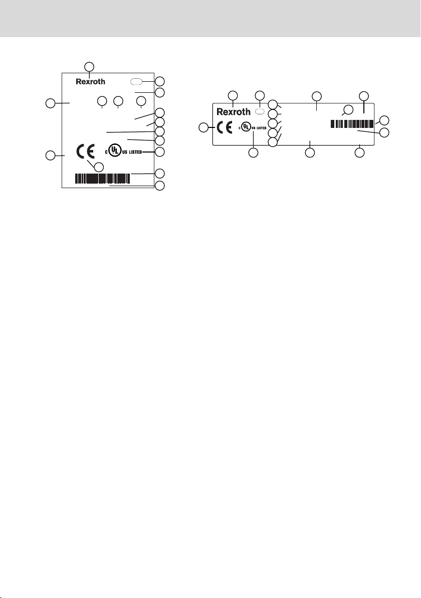
2.1 Product Identification
The type plate is located on the rear panel.
2/37
DOK-SUPPL*-VDPXX.3MTBU-IT02-EN-P
13026
2
3
6
7
7
10
11
12
13
14
9
8
5
4
1
Bosch rexroth Electric Drives and Controls GmbH
D-64711 Erbach Made in Germany
BTV40.1AHB-256S-P5CUN-FW
UN IN 3AC 230V 50760Hz
IN
OUT 10/7,5/5/5/1,5/1,5A max.
I-C-B-T-V
SW-Version V0,002
MNR: 1070170021 -101 03W19
7261
IND.CONT.EQ 17YB
SN: 123456814
15
16
Made in Germany
UN: AC 230V / 115V
IN: 0,7A / 1,4A
MNR: 1070086255 -101
V-Nr: 1
TYP: PCPNL PEN400J1287 IS110-T
Bosch Rexroth Electric Drives and Controls GmbH
D-6471
1 Erbach
SN: 004012652
7261
IND.CONT-EQ 17YB
XXXXXXXXXXXXXXXXX
I-C-B-H-T-V
FD: 05W01
1
2
3
4
8
9
5
10
6
12
11
13
14
15
16
VDP 15.3, 18.3, 21.3 Multitouch
Bosch Rexroth AG
Using the Safety Instructions
1 Logotype
2 Division or plant number
3 Type code (type designation code)
4 Parts number
5 State of revision
6 Date of manufacture (yyWww)
7 Nominal voltage
8 Nominal current
Fig. 2-1: Type plates, example
2.2 Scope of Delivery
● Operating display
● Safety instructions
● Mounting kit
● 24 V female connector strip
3
Using the Safety Instructions
3.1 Safety Instructions – Structure
The safety instructions are structured as follows:
DOK-SUPPL*-VDPXX.3MTBU-IT02-EN-P
9 Test marking
10 Version number
11 CE marking
12 Underwriters Laboratories Inc. mark
13 Serial number as barcode
14 Serial number
15 Designation of origin
16 Company address
3/37
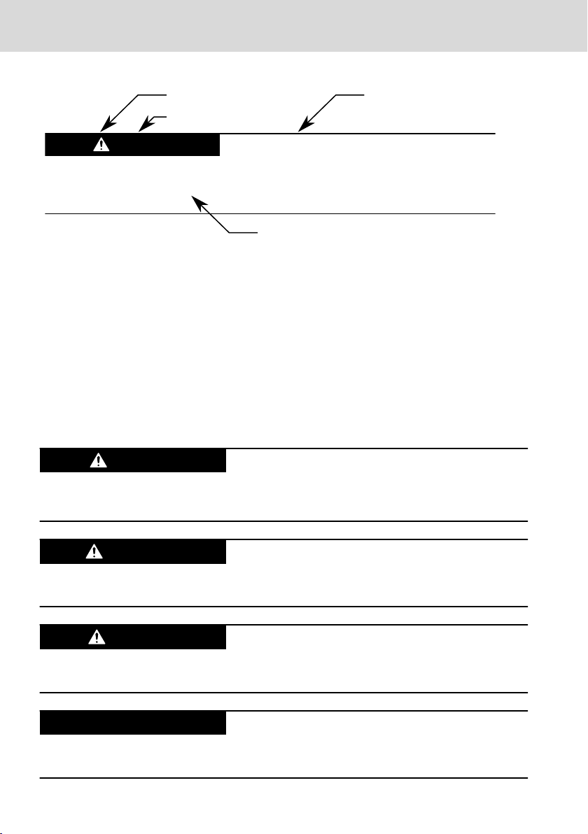
Burns and chemical burns due to wrong
battery treatment!
CAUTION
Safety alert symbol
Signal word
Consequences and
source of danger
Avoiding danger
Do not open the batteries and do not heat them over 80 °C.
DANGER
WARNING
CAUTION
NOTICE
Bosch Rexroth AG
Using the Safety Instructions
Fig. 3-1: Safety instructions – Structure
VDP 15.3, 18.3, 21.3 Multitouch
3.2 Explaining Signal Words and Safety Alert Symbol
The safety instructions in this documentation contain specific signal words (danger, warning, caution, notice) and, if necessary, a safety alert symbol (according
to ANSI Z535.6-2006).
The signal word is meant to draw the reader's attention to the safety instruction
and signifies the degree of danger.
The safety alert symbol (a triangle with an exclamation point), which precedes
the signal words danger,warning and caution is used to alert the reader to personal injury hazards.
In case of non-compliance with this safety instruction, death or serious injury
will occur.
In case of non-compliance with this safety instruction, death or serious injury
can occur.
In case of non-compliance with this safety instruction, minor or moderate injury
could occur.
In case of non-compliance with this safety instruction, property damage could
occur.
4/37
DOK-SUPPL*-VDPXX.3MTBU-IT02-EN-P

NOTICE
VDP 15.3, 18.3, 21.3 Multitouch
Bosch Rexroth AG
Intended Use
3.3 Symbols Used
Notes are displayed as follows:
This is a note.
Tips are displayed as follows:
This is a tip.
4 Intended Use
The Bosch Rexroth operator terminals are passive operation and visualization
terminals. They form a PC-based operator terminal when used with a Bosch
Rexroth control cabinet PC.
Danger of destruction of the device if not expressly stated accessories, mounting parts and
other components, cables, lines, software and
firmware are used.
The operator displays may be used only as intended and with the accessories,
mounting parts and other components specified in this documentation. Components that are not expressly mentioned must neither be attached nor connected. The same is valid for cables and lines.
Operation must only be carried out with the hardware component configurations and combinations that are expressly specified and with the software and
firmware indicated and specified in the respective documentation and functional descriptions.
Typical areas of application of the operator displays are:
● Handling systems and assembly systems
● Packaging and food processing machines
● Printing machines and paper converting machines
● Machine tools
● Wood processing machines
The operator displays may only be operated under the mounting and installation
conditions, the position, and the ambient conditions (temperature, degree of
protection, humidity, EMC etc.) specified in this documentation.
DOK-SUPPL*-VDPXX.3MTBU-IT02-EN-P
5/37

NOTICE
Bosch Rexroth AG
Spare Parts, Accessories and Wear Parts
Risk of destroying the touch screen or the front
panel by using inappropriate items.
Operate the touch screen only with your finger or with a special touch pen
(parts number 1070923266).
VDP 15.3, 18.3, 21.3 Multitouch
5 Spare Parts, Accessories and Wear Parts
5.1 Y-Repeater
Connecting unit to connect two operator displays featuring the same resolution
and the same version to one control cabinet PC.
Ordering code Part number Description
VAC01.1S-YD1-TCES R911172852 Y-repeater for CDI interface
Tab. 5-1: Y-Repeater
5.2 External 24 V Power Supply Unit
Ordering code Part number Description
VAP01.1H-W23-024-010-NN R911171065 External 24 V power supply unit for the
IndraControl V devices
Tab. 5-2: External 24 V power supply unit for the operator display
5.3 Uninterruptible Power Supply (UPS)
Ordering code Part number Description
VAU01.1U-024-024-240-NN R911171024 Uninterruptible power supply
DC 24 V, 240 watts with USB interface
Tab. 5-3: Uninterruptible power supply (UPS)
5.4 Connecting Cables for the CDI Interface
Malfunctions caused by using inappropriate CDI cables.
Use only cables listed in the following overview.
Ordering code Part number Description
RKB0008/000,5 (*******-*******-*******) R911171484 Length: 0.5 m
RKB0008/001,0 (*******-*******-*******) R911171485 Length: 1 m
RKB0008/002,5 (*******-*******-*******) R911170151 Length: 2.5 m
RKB0008/005,0 (*******-*******-*******) R911170152 Length: 5 m
6/37
DOK-SUPPL*-VDPXX.3MTBU-IT02-EN-P
VDP 15.3, 18.3, 21.3 Multitouch Bosch Rexroth AG
Ambient Conditions
Ordering code Part number Description
RKB0008/007,5 (*******-*******-*******) R911172971 Length: 7.5 m
RKB0008/010,0 (*******-*******-*******) R911170153 Length: 10 m
RKB0008/015,0 (*******-*******-*******) R911171183 Length: 15 m
RKB0008/020,0 (*******-*******-*******) R911171184 Length: 20 m
RKB0008/025,0 (*******-*******-*******) R911170154 Length: 25 m
RKB0008/030,0 (*******-*******-*******) R911171381 Length: 30 m
RKB0008/035,0 (*******-*******-*******) R911171369 Length: 35 m
RKB0008/040,0 (*******-*******-*******) R911171382 Length: 40 m
RKB0008/050,0 (*******-*******-*******) R911171383 Length: 50 m
Tab. 5-4: Connecting cables to control cabinet PC, panel PC and operator display
Further cable lengths are available on request.
Two cables are always required to establish a connection between
the VxB and the VDP.
5.5 Wear Parts
Wear parts are not subject to any warranty.
Backlight
The service life of the backlight is limited. After this time has been exceeded,
the backlight will produce only 50 % of its original brightness. The service life is
approx. 50,000 hours at an ambient temperature of 25 °C.
6
Ambient Conditions
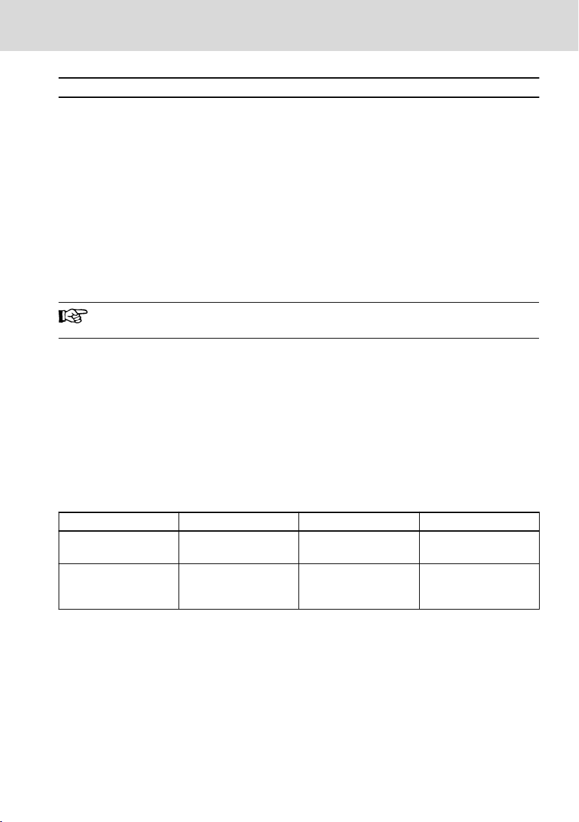
In operation Transport Storage
Max. ambient tempera-
ture
Max. temperature gradi-
ent
DOK-SUPPL*-VDPXX.3MTBU-IT02-EN-P
+0 ℃ to +50 ℃ -20 ℃ to +60 ℃ -20 ℃ to +60 ℃
Temporal temperature
changes up to 3 K per
minute
Temporal temperature
changes up to 3 K per
minute
Temporal temperature
changes up to 3 K per
minute
7/37
Bosch Rexroth AG
VDP 15.3, 18.3, 21.3 Multitouch
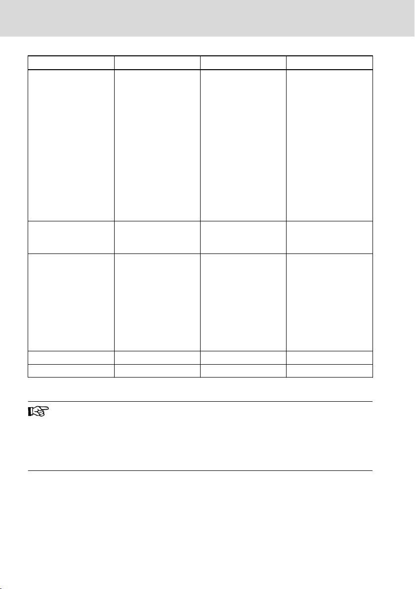
Ambient Conditions
In operation Transport Storage
Humidity Min. relative humidity:
5 %
Max. relative humidity:
85 %
Min. absolute humidity:
3
1 g/m
Max. absolute humidity:
3
25 g/m
Condensation not al-
lowed
Corresponds to climatic
class 3K3 acc. to EN
60721-3-3
Air pressure Up to 3000 m above sea
level acc. to EN
61131-2
Mechanical strength Max. vibration:
Frequency range: 10 Hz
to 150 Hz
Excursion: 0.075 mm at
10 Hz to 57 Hz
Min. relative humidity:
5 %
Max. relative humidity:
75 %
Min. absolute humidity:
3
1 g/m
Max. absolute humidity:
3
25 g/m
Condensation not al-
lowed
Corresponds to climatic
class 2K2 acc. to EN
60721-3-2
Up to 3000 m above sea
level acc. to EN
61131-2
Max. shock:
15 g 11 ms
acc. to EN 60068-2-27,
no disturbance of the
function
Min. relative humidity:
5 %
Max. relative humidity:
85 %
Min. absolute humidity:
1 g/m
Max. absolute humidity:
25 g/m
Condensation not allowed
Corresponds to climatic
class 1K2 acc. to EN
60721-3-1
Up to 3000 m above sea
level acc. to EN
61131-2
Max. shock:
15 g 11 ms
acc. to EN 60068-2-27,
no disturbance of the
function
Acceleration: 1 g at
57 Hz to 150 Hz
acc. to EN 600068-2-6
Contamination level 2 2 2
Overvoltage category 2 - -
3
3
Tab. 6-1: Ambient conditions
The ambient air must not contain acids, alkaline solutions, corrosive
agents, salts, metal vapours, and other electrically conductive contaminants in high concentrations.
The ambient air must be dust-free. Housing and installation compartments must at least comply with degree of protection IP 54 according to DIN VDE 0470-1.
8/37
DOK-SUPPL*-VDPXX.3MTBU-IT02-EN-P
 Loading...