

Bosch EL-51866-40, EL-51866-30 Installation And Operating Instructions Manual
Power Max 2 Charging Station
en Installation and Operating Instructions
fr Guide d’installation/mode d’emploi

en | 2 | Installation and Operating Instructions | Power Max 2 Charging Station
579367 | REV A | 25.07.2016

Installation and Operating Instructions | Power Max 2 Charging Station | 3 | en
Contents English ............4
Sommaire Français .........14
579367 | REV A | 25.07.2016

en | 4 | Installation and Operating Instructions | Power Max 2 Charging Station
Table of Contents
1 Introduction 5
1.1 Applications 5
2 Important Safety Warnings and Instructions 5
3 About the Charger 5
4 Installation 6
4.1 Important SAFETY WARNINGS and Instructions 6
4.2 Grounding Instructions 6
4.3 Recommended Tools 6
4.4 Installing the Power Max 2 Charging Station 6
5 Specications 8
6 Operating Instructions 9
6.1 Instruction Pertaining to the Risk of Electric Shock 9
6.2 Power On/Off Switch 9
6.3 Status Indicator 9
6.4 Charging an Electric Vehicle 9
7 Additional Information 10
7.1 Network Setting (EL-51866-4025P only) 10
7.2 Log File Download and Firmware Upgrade by USB 10
7.3 Auto Restart 10
7.4 Power Outage Recovery 10
7.5 Remote Control (EL-51866-4025P only) 10
8 Troubleshooting 10
9 Important Notices 11
9.1 Limited Warranty 11
9.2 Disclaimer 11
9.3 Limitation of Liability 11
9.4 Copyrights, Trademarks 11
579367 | REV A | 25.07.2016
Installation and Operating Instructions | Power Max 2 Charging Station | 5 | en
1 Introduction
The Power Max 2 Charging Station is designed for the
North American market to charge plug-in electric vehicles
(PHEV) and battery electric vehicles (BEV).
This document provides instructions for the Power Max 2
Charging Station and is not for use for any other product.
Before installation or use of this product, you should review
this manual carefully and consult with a licensed contractor,
licensed electrician, or trained installation expert to ensure
compliance with building codes and safety standards.
1.1 Applications
} Residential
} Private and public parking facilities
} Fleet
} Shopping malls and retailers
} Workplace
Please read and follow these safety warnings and operating
instructions carefully before operating the Power Max 2
Charging Station. Failure to follow these instructions may
result in serious injury or property damage.
2 Important Safety Warnings
and Instructions
IMPORTANT SAFETY INSTRUCTIONS. SAVE
THESE INSTRUCTIONS.
Model Current Rating
EL-51866-40XX 50 A
EL-51866-30XX 40 A
CAUTION
Toreducetheriskofrein cord-connected units,
connect only to a circuit provided with maximum
branch circuit overcurrent protection as shown
below in accordance with the National Electrical
Code, ANSI/NFPA 70.
Model Current Rating
EL-51866-40XX 50 A
EL-51866-30XX 50 A
} The Power Max 2 Charging Station shall be installed only
by a licensed contractor, and/or a licensed electrician in
accordance with all applicable state, local and national
electrical codes and standards.
} Before installing the Power Max 2 Charging Station,
review this manual carefully and consult with a licensed
contractor, licensed electrician and trained installation
expert to ensure compliance with local building
practices, climate conditions, safety standards, and
state and local codes.
} Use appropriate protection when connecting to the main
power distribution cable.
WARNING!
Disconnect electrical power before installing
the Power Max 2 Charging Station. Failure to do
so may cause physical injury or damage to the
electrical system and charging unit.
} Read all the instructions before using this product.
} Children should be supervised when this product is
used around children.
} Do not put ngers into the EV connector.
} Do not use this product if the exible power cord or EV
cable are frayed, have broken insulation, or display any
other signs of damage.
} Do not use this product if the enclosure or the EV connector
is broken, cracked, open, or show any other signs of damage.
} A device employing pressure terminal connectors for
eld wiring connections shall be provided with
instructions specifying a range of values or a nominal
value of tightening torque to be applied to the clamping
screws of the terminal connectors.
CAUTION
Toreducetheriskofrein hard-wired units,
connect the unit only to a circuit provided with
maximum branch circuit overcurrent protection
as show below in accordance with the National
Electrical Code, ANSI/NFPA 70.
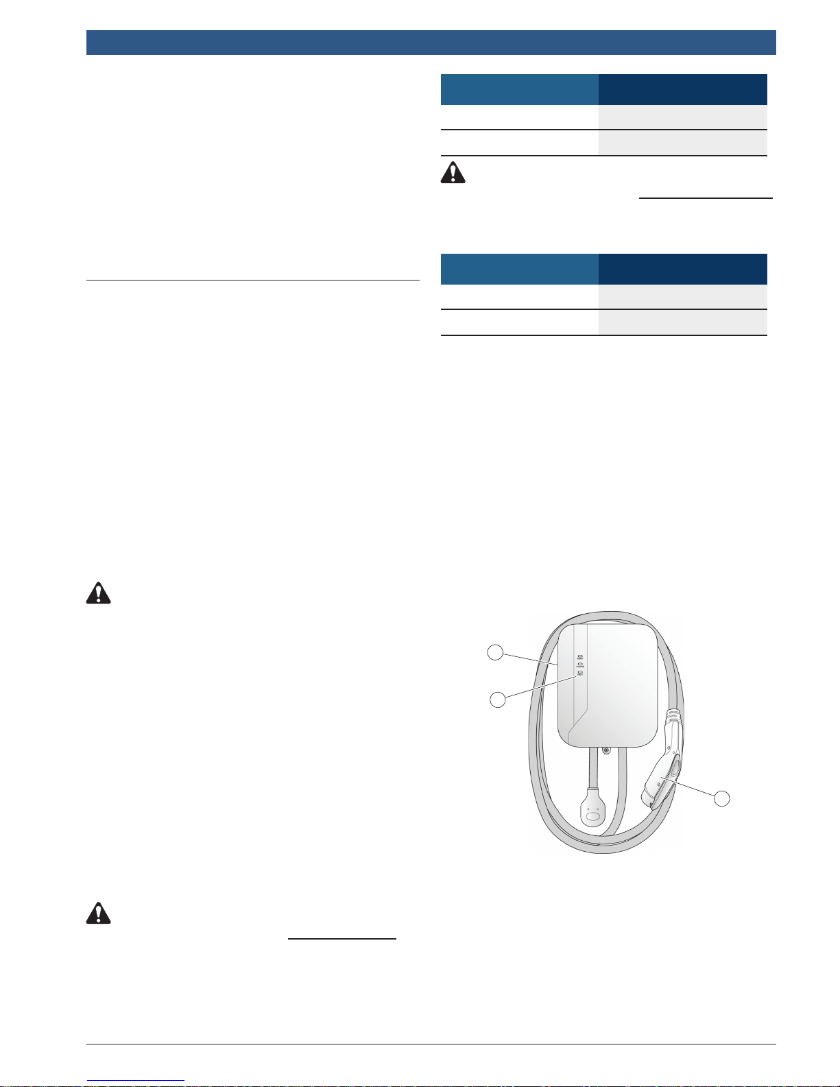
3 About the Charger
1
2
3
1. On/Off switch
2. Status indicator
} Ready
} Charge
} Fault
3. Charging plug
} SAE J1772 compliant
579367 | REV A | 25.07.2016
en | 6 | Installation and Operating Instructions | Power Max 2 Charging Station
4 Installation
4.1 Important SAFETY WARNINGS and
Instructions
IMPORTANT SAFETY INSTRUCTIONS. SAVE
THESE INSTRUCTIONS.
WARNING
Dangerofelectricalshockorinjury.Turnoff
power at the panel board or load center before
workinginsidetheequipmentorremovingany
component. Do not remove circuit protective
devices or any other component until the
power is turned off.
The Power Max 2 Charging Station shall be installed only
by a licensed contractor, and/or a licensed electrician in
accordance with all applicable state, local and national
electrical codes and standards.
Before installing the Power Max 2 Charging Station, review
this manual carefully and consult with a licensed
contractor, licensed electrician, and trained installation
expert to ensure compliance with local building practices,
climate conditions, safety standards, and state and local
codes.
Use appropriate protection when connecting to the main
power distribution cable.
4.2 Grounding Instructions
The Power Max 2 Charging Station must be connected to a
grounded, metal, permanent wiring system; or an equipment
grounding conductor must be run with the circuit conductors
and connected to the equipment grounding terminal or lead on
the product.
4.3 Recommended Tools
The following tools are recommended for the Power Max 2
Charging Station installation:
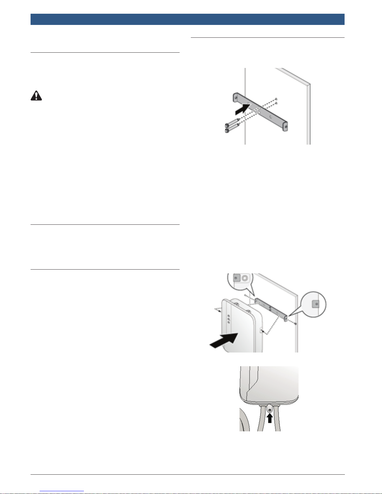
4.4 Installing the Power Max 2
Charging Station
1. See Figure 4-1. Use the supplied template to locate the
mounting bracket above the electrical receptacle.
Figure 4-1.
Note: Follow applicable accessibility requirements for the
mounting position. The unit shall be mounted at a sufcient
height from grade such that the height of the storage means
is located between 600 mm (24 in.) and 1.2 m (4 ft) from
grade per NEC Article 625.
2. Secure the mounting bracket and the optional cable
hanger bracket to the wall with appropriate bolts as
follows:
• For masonry walls use 1/4-in. expansion bolts and
torque to 78 lb•in (8.8 N•m).
• For nished walls supported by wood studs use #8
wood screws of 2 in. or above screw length and
torque to 26 lb•in (3 N•m).
3. See Figure 4-2. Align the screw holes of the mounting
bracket with the Power Max 2 Charging Station. Install
and secure the Power Max 2 Charging Station on the
mounting bracket with the two (2) Torx T30 screws
supplied. Torque to 13 lb·in (1.5 N·m).
} Vendor supplied accessories and components:
– Mounting bracket
– Mounting template
– Cable hanger bracket (optional)
– Torx T30 bolts (x2) for securing the Power Max
2 Charging Station to the mounting bracket
– 1/4-in. expansion bolts (x3)
– No. 8 wood screws (x3)
– Terminal crimps (x3)
} Installer-supplied components:
– Conduit of appropriate trade size for power wire
– NEMA 6-50R receptacle
} Recommended tools:
– Torx T30 screwdriver
– Torx T20 screwdriver
– Phillips #2 screwdriver
– Flathead slotted #5 screwdriver
– Terminal crimper
4. See Figure 4-3. Secure mounting tab to wall.
Figure 4-2.
Figure 4-3.
5. If installed above a receptacle, the installation is
complete. For hardwired installation, continue to Step 6.
579367 | REV A | 25.07.2016
Installation and Operating Instructions | Power Max 2 Charging Station | 7 | en
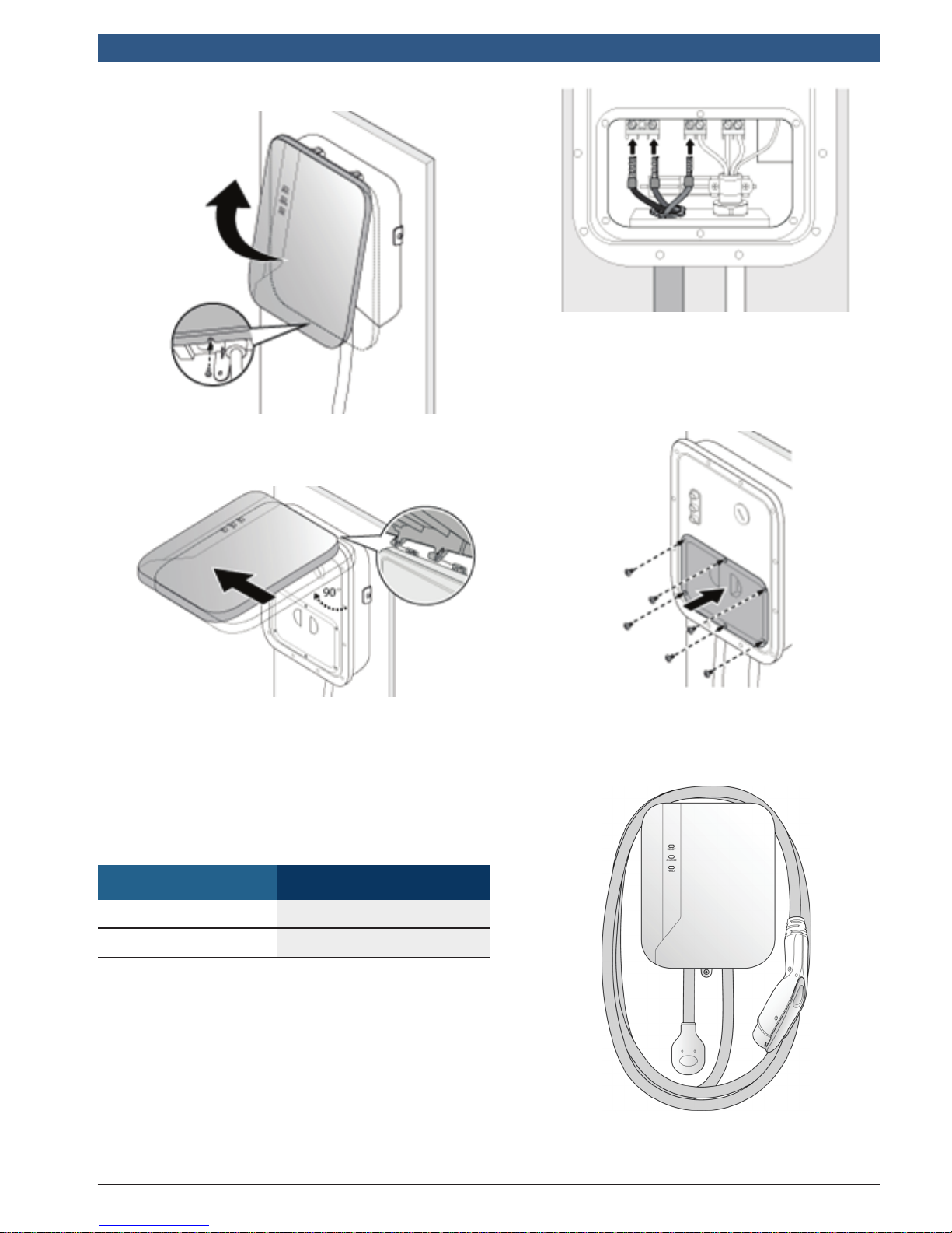
6. See Figure 4-4. Remove the screw located at the bottom of
the front cover.
Figure 4-4.
7. See Figure 4-5. Hold the front cover. Flip upward and then
shift leftward to separate the front cover from the charger.
Figure 4-6.
Note: Choose appropriate conduit in accordance with
all applicable state, local, and national electrical codes
and standards.
10. See Figure 4-7. Replace the compartment cover
and torque to 8.7 lb·in (1.0 N·m).
Figure 4-5.
8. Remove the compartment cover.
9. See Figure 4-6. Use appropriate copper wire with listed
pressure terminal connectors, such as ring and fork types,
on the end of the conductor before attachment to the
terminal blocks. Keep enough length of wire to facilitate
installation. Connect each terminal to the correct terminal
input block connector in the compartment and torque to
19 lb•in (2.2 N•m).
Model CopperWireType
EL-51866-40XX No. 6 AWG, 90 °C
EL-51866-30XX No. 8 AWG, 75 °C or 90 ºC
Figure 4-7.
11. Replace the front cover by aligning the hinge on
the top. Secure the front cover by the bottom
screw, torque to 10.4 lb·in (1.2 N·m).
12. See Figure 4-8. Place the charger cable properly.
Figure 4-8.
579367 | REV A | 25.07.2016
en |8| Installation and Operating Instructions | Power Max 2 Charging Station
5 Specications
Model EL-51866-30XX EL51866-40XX
Charging Interface SAE J1772 compliant plug
Input Rating
Wiring for Hard-wired Models L1, L2, and Ground, hard-wired with terminal block; bottom-fed
Wall Plug for Cord-connected Models NEMA 6-50P
Output Rating
Standby Power <5W
Metering Embedded non-revenue grade meter with 1% accuracy
Internal Residual Current Detection 20 mA CCID per UL 2231
Upstream Breaker
Electrical Protection
Status Indicators AC present, charging, fault
Buttons/Switches Charger on/off, stop charging
208-240 Vac, single-phase,
30 A max, 60 Hz
208-240 Vac, single phase, 30 A max.,
60 Hz, 7.2 kW
2-pole 40 A breaker on dedicated
circuit, non-GFCI type (if hard-wired)
Over current, short circuit, over voltage, under voltage, ground fault,
surge protection, over temperature
208-240 Vac, single-phase,
40 A max, 60 Hz
208-240 Vac, single phase, 40 A
max., 60 Hz, 9.6 kW
2-pole 50 A breaker on dedicated circuit, non-GFCI type
Option: Network Interface WLAN
Operating Temperature -22°F to +122°F (-30°C to +50°C)
Humidity 95% related humidity, non-condensing
Charging Cable Length 18 ft (5.5 m) or 25 ft (7.6 m) straight cable
Ingress Protection Type 3R
Cooling Natural cooling
Dimension (W×H×D)
Net Weight 5 lb (2 kg) excluding charging connector and cable
Certicate UL, cUL
12.6×10.3×4.5 in. (320×260×115 mm), excluding charging cable, mounting plate, and cable holder
579367 | REV A | 25.07.2016
 Loading...