

Page 1
9000967051 940130
^0 Montageanleitung
Installation instructions
^0 Notice de montage
^0 Istruzioni per il montaggio
Installatievoorschrift
Monteringsvejledning
^1 Instrugòes de montagem
Instrucciones de montaje
1
/
у
><>x4 '
/
06^:
Ч
o'
90°
*7
el
05nYÌ£^ еукатаотаоп^
no
Monteringsveiledning
sv
Monteringsanvisning
fi
Asennusohje
ru
Инструкция no монтажу
cs
Montázní návod
Instrukcja montazu
pi
tr
Monta] kilavuzu
Page 2

de
Das müssen Sie beachten
Elektrischer Anschluss: nur durch konzessionierten Fachmann.
Bei Falschanschluss erlischt die Garantie.
Einbau: nur fachgerecht, bei Schäden haftet der Monteur.
Anschlussart: das Gerät entspricht der Schutzklasse I und darf
nur in Verbindung mit Schutzleiteranschluss betrieben werden.
Installation: in der Installation muss ein allpoligerTrennschalter
mit 3 mm Kontaktöffnung vorhanden sein.
Unterbau: keine Kühlgeräte, Geschirrspüler, unbelüftete Backö
fen, Waschmaschinen unterbauen.
Modular- /Kompakt-Geschirrspüler der gleichen Marke können
untergebaut werden. Arbeitsplattendicke mindestens 40 mm.
Wird unter dem Kochfeld ein Backofen eingebaut, kann die
Arbeitsplattendicke von den Maßangaben in dieser Anleitung
abweichen. Beachten Sie die Hinweise in der Montageanleitung
des Backofens.
Zwischenboden: wenn die Kochfeldunterseite berührbar ist,
muss ein Zwischenboden montiert werden.
Fragen Sie im Fachhandel nach einem Zwischenboden als Zube
hör.
Wenn Sie einen eigenen Zwischenboden verwenden, muss der
Mindestabstand zum Netzanschluss des Gerätes 10 mm betra
gen.
Arbeitsplatte: eben, waagrecht, stabil.
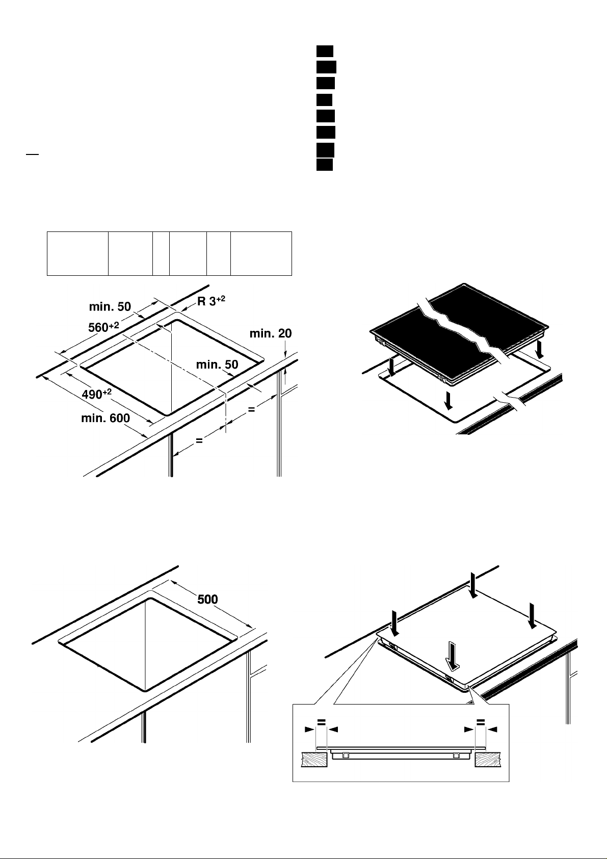
Möbel vorbereiten - Bild 1
Einbaumöbel: mindestens 90°C temperaturbeständig.
Ausschnitt: Mindestabstand zu seitlichen Wänden: 70 mm.
Nach Ausschnittarbeiten Späne entfernen.
Schnittflächen: hitzebeständig versiegeln.
Kochfeld anschließen und einsetzen - Bild 2
Vor Geräteanschluss Hausinstallation überprüfen.
Gerät ohne Anschlussleitung: nur nach Anschlussbild anschlie
ßen. Bei Bedarf beiliegende Kupferbrücken montieren. Netzan
schlussleitung: Typ H05 VV-F oder höherwertig, Adernquerschnitt
min. 1,5 mm^.
Gerät mit vormontierter5-/6-adriger Anschlussleitung: nur ein
geschulter Kundendienst-Techniker darf die Anschlussleitung aus
tauschen.
Einsetzen: Anschlussleitung nicht einklemmen, nicht über scharfe
Kanten führen. Bei untergebautem Backofen Leitung an den hinte
ren Ecken des Backofens zur Anschlussdose führen.
Hinweis: erscheint im Display des Gerätes uHlJU ist es falsch
angeschlossen. Gerätvom Netz trennen, Anschluss überprüfen.
Geflieste Arbeitsplatten: Fliesenfugen mit Silikonkautschuk
abdichten.
Kochfeld ausbauen: Das Gerät spannungslos machen. Kochfeld
von unten herausdrücken.
Kochfeld einsetzen bei vorhandenem
Arbeitsplattenausschnitt mit 500mm Tiefe - Bild 3
1. Kochfeld aufsetzen
2. Kochfeld ausrichten
3. Kochfeld eindrücken
en
The following must be noted
Electrical connection: To be carried out only by a licensed
expert. Incorrect connection will invalidate the warranty.
Installation: To be carried out only by a professional. The fitter is
liable for any damage.
Connection type: The appliance fulfils the requirements of
protection class I and may only be operated in conjunction with an
earth conductor.
Installation: An all-pole isolating switch with at least a 3 mm
contact gap must be included in the installation.
Support: Refrigerators, dishwashers, non-ventilated ovens and
washing machines must not rest on a support.
Modular/compact dishwashers of the same brand can rest on a
support. Work surface thickness must be at least 40 mm.
If an oven is being installed underneath the hob, the work surface
thickness may differ from the dimensions given in these
instructions. Observe the information in the oven installation
instructions.
Partition floor: If the underside of the hob can be touched, a
partition floor must be fitted.
Ask your specialist retailer for a partition floor as an accessory.
If you use your own partition floor, the minimum distance to the
mains connection of the appliance must be 10 mm.
Work surface: Level, horizontal, stable.
Preparing the units - Figure 1
Fitting unit: Heat resistant to at least 90°C.
Cut-out: Minimum distance to the side walls: 70 mm.
After the cutting out work is complete, remove the shavings.
Cut surfaces: Seal with heat-resistant material.
Connecting and fitting the hob - Fig. 2
Before connecting the appliance, check the household installation.
Appliance without power cable: Only connect as per the
connection diagram. If necessary, fit the copper bridge supplied.
Mains power cable: Type H05 VV-F or a higher grade, min. wire
cross-section 1.5 mm^.
Appliance with prefitted 5 or 6-wire power cable: The power
cable must only be replaced by a trained after-sales engineer.
Installing: Do not trap the power cable and do not route it over
sharp edges. If the oven is a built-under type, route the cable on
the rear corners of the oven to the socket.
Note: If uHlJu appears in the display, the appliance has not been
connected correctly. Disconnect the appliance from the mains and
check the connection.
Tiled work surfaces: Seal the tile joints with silicone rubber.
Removing the hob: Disconnect the appliance from the power
supply. Push out the hob from below.
Insert the hob in the existing worktop cut-out with a depth of
500 mm - Figure 3
1. Put the hob in place
2. Align the hob
3. Press in the hob
fr
Consignes à respecter
Branchement électrique : uniquement par un spécialiste agréé.
Toute erreur de branchement annule la garantie.
Encastrement : uniquement selon les règles de l'art, l'installateur
est responsable en cas de dommages.
Type de raccordement : l'appareil correspond à la classe de
protection I et doit uniquement être utilisé avec un raccordement à
la terre.
Installation : l'installation électrique doit comporter un interrupteur
omnipolaire avec une ouverture de contact d'au moins 3 mm.
Sous le plan de travail : ne pas installer d'appareil réfrigérant ni
de lave-vaisselle, de four non ventilé ni de lave-linge.
Il est possible d'installer sous le plan de travail un lave-vaisselle
compact/modulaire de la même marque. Épaisseur minimale du
plan de travail 40 mm.
Si un four est encastré sous la table de cuisson, l'épaisseur du
plan de travail peut différer des indications dimensionnelles
contenues dans cette notice. Respectez les consignes de la notice
de montage du four.
Fond de séparation : s'il est possible de toucher le dessous de la
table de cuisson, il est nécessaire de monter un fond de
séparation.
Des fonds de séparation sont en vente dans le commerce
spécialisé comme accessoire.
Si vous utilisez votre propre fond de séparation, la distance
minimale vers le branchement au secteur de l'appareil doit être de
10 mm.
Plan de travail : plat, horizontal, stable.
Préparation du meuble - fig. 1
Meuble d'encastrement : résistant à une température d'au moins
90°C.
Découpe : distance minimale vers les parois latérales : 70 mm.
Enlever les copeaux après les travaux de découpe.
Chants de la découpe : les sceller de façon thermostable.
Page 3

Raccordement de la table de cuisson et mise en place - fig. 2
Avant de raccorder l'appareil, vérifier l'installation domestique.
Appareil sans câble de raccordement : raccorder
exclusivement selon le schéma de raccordement. En cas de
besoin, monter les ponts en cuivrejoints. Câble de raccordement
secteur : type H05 VV-F ou supérieur, section des fils
min. 1,5 mm^.
Appareil avec câble de raccordement prémonté à 5/6 fils : seul
un technicien formé du SAV est habilité à remplacer le câble de
raccordement.
Mise en place : ne pas coincer le câble de raccordement, ne pas
le tirer par-dessus d'arêtes coupantes. En cas de four installé en
dessous, faire passer le câble aux coins arrière du four vers la
prise de raccordement.
Remarque : Si uHIJIJ apparaît dans l'affichage de l'appareil,
celui-ci n'est pas correctement raccordé. Séparer l'appareil du
secteur, vérifier le branchement.
Plans de travail carrelés : étanchéifier les joints de carrelage
avec un joint en silicone.
Dépose de la table de cuisson : mettre l'appareil hors tension.
Sortir la table de cuisson en la poussant par le bas.
Insertion de la table de cuisson en cas de présence d'une
découpe du plan de travail d'une profondeur de 500 mm - fig. 3
1. Poser la table de cuisson
2. Aligner la table de cuisson
3. Faire rentrer la table de cuisson en appuyant
It
Procedere nel modo seguente
Allacciamento elettrico: solo da parte di un tecnico autorizzato.
In caso di allacciamento scorretto decade la garanzia.
Montaggio: da eseguirsi esclusivamente in modo corretto; in caso
di danni la responsabilità verrà imputata a chi ha eseguito il
montaggio.
Tipo di allacciamento: l'apparecchio rientra nella classe di
protezione I e può essere messo in funzione solo se collegato a un
conduttore di terra.
Installazione: in fase d'installazione è necessario prevedere un
sezionatore universale con un'apertura di contatto di 3 mm.
Sotto l'apparecchio: non è consentito incassare al di sotto
dell'apparecchio frigoriferi, lavastoviglie, forni non ventilati o
lavatrici.
Possono essere montate lavastoviglie modulari/compatte della
stessa marca. Lo spessore del piano di lavoro deve essere di
almeno 40 mm.
Se si installa un forno sotto il piano di cottura, lo spessore del
piano di lavoro può differire dalle dimensioni indicate in questo
manuale. Prestare attenzione alle avvertenze presenti nelle
istruzioni per il montaggio del forno.
Doppiofondo: se è possibile toccare il lato inferiore del piano di
cottura, è necessario montare un doppiofondo.
Richiedere presso un rivenditore specializzato un doppiofondo
come accessorio.
Se si utilizza un proprio doppiofondo, la distanza minima dal
collegamento elettrico dell'apparecchio deve essere di 10 mm.
Piano di lavoro: stabile, in piano e orizzontale.
Preparazione del mobile: figura 1
I mobili da incasso: termostabili almeno fino a90 °C.
Foro di incasso: distanza minima dalle pareti laterali: 70 mm.
Rimuovere i trucioli dopo i lavori di taglio.
Superfici di taglio: sigillare in modo refrattario.
Montaggio e allacciamento: figura 2
Prima dell'allacciamento dell'apparecchio, controllare l'impianto
domestico.
Apparecchio senza cavo di allacciamento: attenersi sempre
allo schema di allacciamento. Se necessario, montare i ponticelli
in rame forniti in dotazione. Cavo di allacciamento alla rete:
modello H05 VV-F o superiore, sezione trasversale fili min. 1,5
mm^.
Apparecchio con cavo di allacciamento premontato a 5-6 fili:
solo un tecnico del servizio assistenza, adeguatamente istruito,
può sostituire il cavo di allacciamento.
Inserimento: fare in modo che il cavo non rimanga incastrato e
non passi su spigoli vivi. In caso di forni sottostanti, portare il cavo
alla presa di collegamento facendolo passare dall'angolo
posteriore del forno.
Nota: se sul display dell'apparecchio compare uHlJu significa
che l'allacciamento non è stato effettuato in modo corretto.
Staccare l'apparecchio dalla rete di alimentazione e controllare
l'allacciamento.
Piani di lavoro piastrellati: chiudere a tenuta le fughe tra le
piastrelle utilizzando gomma siliconica.
Smontaggio del piano di cottura: scollegare l'apparecchio dalla
rete elettrica. Estrarre il piano di cottura spingendolo dal basso.
Montare il piano cottura con foro d'incasso nel piano di lavoro
presente con profondità 500 mm - Figura 3
1. Posizionare il piano cottura
2. Livellare il piano cottura
3. Spingere il piano cottura in sede
nl
Hierop dient u te letten
Elektrische aansluiting: alleen door een erkend vakman. In geval
van een verkeerde aansluiting kernt de garantie te vervallen.
Inbouw: alleen op deskundige wijze, bij schade is de monteur
aansprakelijk.
Aansluitklasse: hot apparaat voldoet aan beveiligingsklasse I en
mag alleen met een geaarde aansluiting worden gebruikt.
Installatie: de installatie dient te beschikken over een schakelaar
met een contactopening van 3 mm.
Onderbouw: geen koelapparaten, vaatwasmachines, ovens
zonder ventilatie of wasmachines onderbouwen.
Er kunnen modulaire/compacte vaatwasmachines van hetzelfde
merk worden ondergebouwd. Werkplaatdikte minstens 40 mm.
Wordt onder de kookplaat een oven ingebouwd, dan kan de
werkplaatdikte afwijken van de afmetingen in deze
gebruiksaanwijzing. Neem de aanwijzingen in de
installatiehandleiding bij de oven in acht.
Tussenschot: wanneer de onderkant van de kookplaat kan
worden aangeraakt, moet er een tussenschot worden gemonteerd.
Informeer in de vakhandel of er een tussenschot als accessoire
verkrijgbaar is.
Wanneer u een eigen tussenschot gebruikt, dient de minimale
afstand tot de netaansluiting van hot toestel 10 mm te bedragen.
Werkblad: vlak, waterpas en stabiel.
Meubel voorbereiden - Afbeelding 1
Inbouwmeubel: tenminste bestand tegen een temperatuur van
90°C.
Uitsnijding: minimale afstand tot de zijwanden: 70 mm.
Na uitsnijwerkzaamheden de spaanders verwijderen.
Snijvlakken: hittebestendig afdichten.
Kookplaat aansluiten en inbrengen - Afbeelding 2
Voor aansluiting van hot toestel de huisinstallatie controleren.
Toestel zonder aansluitkabel: alleen aansluiten volgons hot
aansluitschema. Zo nodig de bijbehorende koperbrug monteren.
Hoofdieiding (netaansluiting): type H05 VV-F of hoogwaardiger,
aderdiameter min. 1,5 mm^.
Toestel voorzien van voorgemonteerde aansluitkabel met 5/6
aders: de aansluitkabel mag alleen worden vervangen door een
technicus die door de klantenservice geinstrueerd is.
Inbrengen: Zorg ervoor dat de aansluitkabel niet beklemd raakt
en niet over scherpe randen wordt geleid. Is er een oven
ondergebouwd, dan de kabel via de achterste hoeken van de oven
naar de aansluitdoos leiden.
Aanwijzing: verschijnt uHIJIJ op hot display van hot toestel, dan
is hot verkeerd aangesloten. De stekker uit hot stopcontact halen,
aansluiting controleren.
Betegelde werkplaten: Voegen van de tegels met
siliconenrubber afdichten.
Kookplaat demonteren: Hot apparaat spanningsloos maken.
Kookplaat van onderuit naar buiten drukken.
Kookplaat inbrengen bij een beschikbare werkplaatuitsnijding
van 500 mm diepte - Afb. 3
1. Kookplaat plaatsen
2. Kookplaat stellen
3. Kookplaat indrukken
Page 4

da
Folgende anvisninger skal overholdes:
Elektrisk tilslutning: Mà kun foretages af en autoriseret
elektriker. Ved forkert tilslutning bortfalder garantiens gyldighed.
Montage: Skai udfores fagligt korrekt, ved evt. skader hotter
montoren.
Tilslutningsmáde: Apparatet opfylder beskyttelsesklasse I og mà
udelukkende anvendes med tilsluttetjordforbindelse.
Installation: Der skal forefindes en alpolet skilleafbryder med 3
mm kontaktafstand i Installationen.
Indbygning: Der mà ikke indbygges kole-Zfryseskabe,
opvaskemaskiner, uventilerede ovne ellervaskemaskiner under
apparatet.
Modul-/kompakt-opvaskemaskiner af samme m^rke kan
indbygges nedenunder. Bordpladetykkelse minimum 40 mm.
Hvis der indbygges en ovn under kogesektionen, kan bordpladens
tykkelse afvige fra de angivne mài i denne vejiedning. Folg
anvisningerne i ovnens montagevejiedning.
Mellembunde: Hvis kogesektionens underside kan berores, skal
der monteres en mellembund.
Der kan fàs mellembunde som tilbehor i en specialbutik.
Hvis der anvendes en anden mellembund, skal afstanden til
apparatets nettilslutning minimumv^re 10 mm.
Bordplade: Plan, vandret, stabil.
Forberedelse af kokkenelement - figur 1
Kokkenelementer til indbygning: Som minimum
temperaturbeständige til 90®C.
Udsksring: Mindste afstand til sidev^gge: 70mm.
Fjern alle spàner, nàr udsk^ringen er f^rdig.
Snitflader: Skal forsynes med varmebestandig forsegling.
Tilslutning og isstning af kogesektion - figur 2
Kontroller den elektriske installation i huset, inden apparatet
tilsluttes.
Apparat uden tilslutningsledning: Skal tilsluttes efter
tilslutningsbillede. Monter om nodvendigt de leverede
kobberpolbroer. Nettilslutningsledning: Type H05 VV-F eller bedre,
ledertv^rsnit min. 1,5 mm^.
Apparat med formonteret netledning med 5/6 ledere:
Tilslutningsledningen mà kun udskiftes af en uddannet
kundeservicetekniker.
Isstning: Tilslutningsledningen mà ikke komme i klemme og ikke
l^gges over skarpe kanter. Hvis der er indbygget en ovn
nedenunder, skal ledningen fores over ovnens hagerste hjorner til
tilslutningsstikket.
Bemerk: Hvis uHlJU vises pà apparatets display, er det tilsluttet
forkert. Afbryd forbindelsen til stromforsyningen, og kontroller
tilslutningen.
Bordplader med fliser: T^tn fugerne med silikonegummi.
Demontere kogesektion: Apparatet skal gores sp^ndingslost.
Tryk kogesektionen op nedefra.
Isstning af kogesektion ved eksisterende udsksring i
bordplade med en dybde pá 500 mm - figur 3
1. S^t kogesektionen i udsk^ringen
2. Indjuster kogesektionen
3. Tryk kogesektionen pà plads
Pt
Indicagoes a respeitar
Ligagáo elétrica: deve ser efetuada apenas por um especialista.
Urna ligagao errada anula a garantía.
Montagem: conforme especificado, em caso de danos, a
responsabilidade será do instalador.
Tipo de ligagáo: o aparelho corresponde à classe de protegào I e
deve apenas funcionar com um condutor de protegào.
Instalagao: na instalagào deverà existir um dispositivo de corte
omnipolar com urna abertura de contato de, pelo menos, 3 mm.
Instalagao por baixo do equipamento: por baixo nao devem ser
instalados equipamentos de frio, máquinas de lavar loiga, fornos
sem ventilagào, máquinas de lavar roupa.
As máquinas de lavar loiga modulares/compactas da mesma
marca podem ser instaladas por baixo do equipamento.
Espessura da bancada, no minimo, 40 mm.
Se for montado um forno por debaixo da placa de cozinhar, a
espessura da bancada pode divergir das medidas indicadas neste
manual. Respeite as indicagóes constantes das instrugóes de
montagem.
Divisòria: se for possível tocar na parte inferior da placa de
cozinhar, é necessàrio instalar urna divisòria.
Procure no comércio especializado urna divisòria como acessòrio.
Se usar urna divisòria pròpria, terà de observar urna distància
mínima de 10 mm à fonte de alimentagào do aparelho.
Bancada: plana, horizontal, robusta.
Preparar o móvei - figura 1
MóveI de montagem: resistencia mínima a temperaturas até
90°C.
Abertura recortada: distància mínima às paredes laterals::
70 mm.
Depois de proceder aos trabalhos de recorte, remova as aparas.
Superficies cortadas: sele-as de modo a que resistam a
temperaturas elevadas.
Ligar e inserir a piaca de cozinhar - figura 2
Antes de ligar o aparelho, verifique a instalagào da casa.
Aparelho sem cabo de ligagao: ligue apenas de acordo com a
imagem de ligagào. Se necessàrio, monte a ponte de cobre
juntamente fornecida. Cabo de alimentagào: Tipo H05 VV-F ou
superior, secgào do condutor min. 1,5 mm^.
Aparelho com cabo de ligagào pré-montado de 5-/6
condutores: sò um técnico qualificado do servigo de assisténcia
pode substituir o cabo de ligagào.
Instalar: nao entale o cabo de ligagào nem o passe por arestas
vivas. Se existir um forno instalado por baixo, passe o cabo pelos
cantos posteriores do forno até à tomada.
Nota: se aparecer ¡JHlJUno visor do aparelho, a ligagào foi
efetuada incorretamente. Desligue o aparelho da corrente e
verifique a ligagào.
Bancadas com azulejo: Vede as juntas dos azulejos com
silicone.
Desmontar a placa de cozinhar: desligue o aparelho da
corrente. Retire a placa de cozinhar, pressionando por baixo.
Colocar a placa de cozinhar no recorte da bancada de trabalho
existente com 500 mm de profundidade - Figura 3
1. Inserir a placa de cozinhar
2. Alinhar a placa de cozinhar
3. Pressionar a placa de cozinhar para encaixar
es
Se debe tener en cuenta:
Conexión eléctrica: solo a cargo de un técnico especialista
autorizado. Si se hace una conexión incorrecta, la garantía no
tendrá validez.
Montaje: conforme a las reglas profesionales; en caso de daños,
el responsable será el montador.
Tipo de conexión: el aparato pertenece a la clase de protección I
y solo puede utilizarse en combinación con una conexión con
conductor de toma a tierra.
Instalación: para la instalación se necesita un dispositivo de
separación omnipolar con una abertura de contacto de 3 mm
como mínimo.
Montaje bajo encimera: no montar bajo encimeras neveras,
lavavajillas, hornos sin ventilación ni lavadoras.
Los lavavajillas modulares o compactos de la misma marca se
pueden montar bajo encimeras. El grosor de la encimera debe ser
de al menos 40 mm.
Si se monta un horno debajo de una placa de cocción, el grosor de
la encimera puede diferir de las dimensiones indicadas en estas
instrucciones. Observar las indicaciones de las instrucciones de
montaje del horno.
Fondo intermedio: si la parte inferior de la placa de cocción
queda accesible, debe montarse un fondo intermedio.
Pedir en un establecimiento especializado un fondo intermedio
como accesorio.
Si se utiliza un fondo intermedio propio, la distancia mínima de la
conexión a red del aparato debe serde 10 mm.
Encimera: plana, horizontal, estable.
Page 5

Preparación de los muebles - Figura 1
Muebles empotrados: resistentes a una temperatura de90°C
como mínimo.
Hueco: distancia mínima a las paredes laterales: 70 mm.
Retirar las virutas después de los trabajos de corte.
Superficies de corte: sellar con material resistente al calor.
Conexión y montaje de la placa de cocción -
Figura 2
Comprobar la instalación doméstica antes de conectar el aparato.
Aparato sin cable de conexión: conectar según el esquema de
conexión. En caso necesario, montar los puentes de cobre
adjuntos. Cable de conexión a la red: tipo H05 VV-F o superior,
sección del conductor mín. 1,5 mm^.
Aparato con cable de conexión de 5/6 conductores
premontado: la sustitución de cables de conexión solo pueden
ser efectuada por personal del Servicio de Asistencia Técnica
debidamente instruido.
Colocación no aprisionar el cable de conexión ni pasarlo por
bordes afilados. Si hay un horno montado debajo, pasar el cable
por las esquinas traseras del horno hasta la caja de conexión.
Nota: si en la pantalla del aparato aparece uHlJu, significa que
está mal conectado. Separar el aparato de la red y comprobar la
conexión.
Encimeras alicatadas: sellar las juntas entre los azulejos con
caucho de silicona.
Desmontaje de la placa de cocción: desconectar el aparato do
la corriente. Extraer la placa de cocción empujando desde abajo.
Colocar la placa de cocción en el hueco de la encimera
provisto con una profundidad de 500 mm - Figura 3
1. Colocar la placa de cocción
2. Nivelar la placa de cocción
3. Insertar la placa de cocción
el
Auto npènei va npooe^eie
HAcKTpiKq oúvSeon: Móvo ano svav aSeioúxo nAsKTpoAoyo. le
nepiniMoq eo^aApsvqg ouvSeogg naúei va loyúei q eYYÙqoq.
TonoGÉTnoq: Móvo e^eiSiKeupsvq eyKaTaoTaon, oe nepiniMoq
^qpiMV Tqv euOúvq ^spei o eyKaTaoTáTqg.
Tpónoq oúvSeonq: H ouoKeuq aviancxpiveiai oiqv Kainyopia
npooTaoiaq I xai eniTpsneiai va AeiToupyei póvo oe ouvSuaopó pe
ouvSeon ayMyoù npooTaolaq (yelMoq).
EYKaTàoTaoq: Iiqv eyKaTaoTaon npsnei va unapyei pia Siàia^q
SiaKonqq óAmv tmv oóAmv pe sva Sióksvo sna^qq 3mm.
TonoGÉTnoq kótm anò tov nàyKO spyaoiaq: Kapia TonoGsTqoq
KÒTM anò TOV nòyKO spyaoiaq ^uysiMV, nAuviqpÌMV niÒTMV,
^oùpvMV X“pi^ aspiopò, nAuvTqpÌMV poùxMv.
AopooToixeiMTà/oupnoYq nAuviqpia niÒTMV iqq iòiaq pàpxaq
pnopoùv va TonoGsTqGouv anò kòtm. Ràxoq nayKou spyaoiaq to
AiyÒTspo 40 mm.
Eòv KÒTM anò pia pàoq eotimv TonoGsTqGsi svaq ^oùpvoq, pnopsi
va òia^spsi To nòxoq tou nòyKou spyaoiaqanò Tiq Tipsq tmv
òiaoTàoEMV OS auTsq Tiq oSqyisq. npoosfjTS Tiqunoòsi^siq OTiq
oòqyisq ouvappoAòyqoqq tou ^oùpvou.
EvSiàpeoo^ nÓToq: Eòv q kòtm pspià Tqp pòoqq eotimv sivai
npooiTq, npsnsi va TonoGsTqGsi èvaq svòiàpsooq nÒToq.
PMTqoTE OTa eiòikò xaTaoTqpaTa yia èvov svòiàpsoo nÒTOMq
E^òpTqpa.
Eòv xpqoiponoiqoETE Èva òikò oaq svòiàpsoo nÒTO, npsnsi q
sAàxioTq anòoTaoq anò Tq oùvòsoq oto òìktuo Tqq ouoKsuqq va
sivai 10 mm.
nòyKoq epyaoiaq: Eninsòoq, opi^òvTioq, OTaOspòq.
nposToipaoia tou VTOuAamoù - Eik. 1
EvTOixi^ópeva VTOuAània: AvOsktikò OTq OsppoKpaoia to AiyÒTspo
psxpi 90°C.
Avoiyp«: EAàxioTq anòoTaoq anò Ta nAaìvà ToixMpaTa: 70 mm.
MsTÒ Tiq spyaoisq Konqq tmv avoiypÒTMV anopaKpùvsTS Ta
anòpAqTa (npioviòia, yps^ia).
Em^àveieq Topqq: I^payioTE Tiq p’ sva OTEvavonoiqTiKÒ uAikò
avOsKTiKÒ OTq OsppÒTqTa.
lùvóeon Kai TonoSèTnog ßaon^ eoTiùv - Eik. 2
Rpiv Tq oùvòsoq Tqq ouoKSuqq sAsy^TS Tqv oiKiaxq qAsKTpixq
syKaTàoTaoq.
ZuoKCug X^P'9 KoAùòio DÓvòcoqq: Zuvòsote Tq ouoKsuq pòvo
oùp^Mva ps TO oxsòio oùvòsoqq. Zs nspinTMoq nou xpsià^sTai,
TonoOsTqoTE Ta ouvqppsva xàAxiva s^apTqpaTa ys^upMoqq.
KaAMÒio oùvòsoqq oto òìktuo tou psùpaToq: Tùnoq H05 VV-F q
ovMTspo, òiaTopq kAmvou sAàx. 1,5 mm^.
ZuoKCug pe qöq TonoGeTqpcvo koAùòio oúvóeoqq 5/6 kAúvuv:
Mòvo svaq SKnaiòsupsvoq TSXviKÒq tou TpqpaToq s^unqpsTqoqq
nsAaTMV sniTpsnsTai va avTiKaTaoTqosi to koAmòio oùvòsoqq.
TonoGéTnoq: Mq payKMOSTS to koAmòio oùvòsoqq, pqv to
nspàosTE nàvM anò KO^Tspsq axpsq. Zs nspinTMoq nou o ^oùpvoq
sivai TonoOsTqpsvoq anò xaTM oòqypoTS to koAmòio OTiq nioM
yMvisq TOU ^oupvou npoq to koutì oùvòsoqq.
Ynóòei^q: Eòv OTqv oOòvq evòeì^emv Tqq ouoKsuqq sp^ovi^sTai I
Huu, TÒTE q oùvòsoq sivai AàOoq. AnoouvòsoTE Tq ouoKsuq anò to
qAsKTpiKÒ ÒÌKTUO, sAsy^TS Tq oùvòsoq.
n«YKOi epyaoiaq enevòupevoi pe nAaxiòia: ZTsyavonoiqoTE Touq
appoùq TMV nAaKiòÌMV ps kooutooùk oiAiKÒvqq.
A^aipeog rqq pàoqq eoriùv: ©sots Tq ouoKsuq SKTÒq TÓoqq.
ZnpM^TE anò KÒTM Tq pàoq eotimv npoq Ta s^m.
TonoGeTgoTe rq paog eoTiùv oe éva u^iOTÒpevo òvoiypa tou
nÒYKOu epyaoiaq pe 500 mm pùGoq - Eik.3
1. TonoGsTqoTS Tq pàoq eotimv
2. EuGuypappìoTS Tq pàoq eotimv
3. nisoTE psoa Tq pàoq eotimv
no
Dette mà du v^re oppmerksom pà
Elektrisk tilkobling skal bare utferes av en autorisert fagperson.
Garantien bortfallerved feil i tilkoblingen.
Innbygging skal utferes fagmessig. Monteren holdes ansvarlig for
eventuelle skader.
Tilkoblingstype: Apparatet or i samovar med beskyttelseskiasse I
og mà bare kobles til jordet stikkontakt.
Installasjon: I installasjonen skal dot inngà en flerpolet skillebryter
med 3 mm kontaktàpning.
Underbygging: Enheten skal ikke monteros over kjeleapparater,
oppvaskmaskiner, stekeovner uten lufting eller vaskemaskiner.
Modular/kompakt oppvaskmaskin av samme merke kan bygges
inn i kjekkenseksjonen. Arbeidsplatetykkelse minst 40 mm.
Om man bygger inn en stekeovn under platetoppen, kan man
avvike fra den angitte standardtykkelsen pà arbeidsplaten i donne
veiledningen. Felg veiledningen i monteringsanvisningen til
stekeovnen.
Mellombunn: Dersom undersiden av kokesonen kan bereres, mà
dot monteros en mellombunn.
Spor i faghandelen etter mellombunn som tilbeher.
Ved mentoring av egen mellombunn, skal minsteavstanden til
apparatets stremtiikobling v^re 10 mm.
Arbeidsplate: Jevn, vannrett, stabil.
Klargjoring av kjokkenelementene - figur 1
Innbyggingselementer: mà tàle temperaturer pà minst 90 °C.
Utskjsring: minsteavstand til sideveggene: 70 mm.
Fjern spon etter utskj^ringsarbeider.
Snittfiater: mà gjeres varmebestandige.
Innsetting og tilkobling av kokesonen - figur 2
Fer apparatet kobles til, mà husanlegget kontrolleres.
Apparat Uten tilkoblingsledning: má kun kobles til etter
tilkoblingsskissen. Montervedlagte kobberstrapperved behov.
Nettiedning: Type H05 VV-F eller heyere, ledertverrsnitt min. 1,5
mm^.
Apparat med forhándsmontert tilkoblingsledning med 5 eller
6 ledere: Tilkoblingsledningen mà kun byttes ut av en oppl^rt
servicetekniker.
Innsetting: Tilkoblingsledningen mà ikke komme i kiem eller
trekkes over skarpe kanter. Hvis det er montert stekeovn under
kokesonen, mà ledningen legges rundt de bakre hjornene pà
stekeovnen og til stikkontakten.
Merknad: Vises uHlJu i apparatets display, er dot feiltiikoblet.
Koble apparatet fra stromnettet, og kontroller tilkoblingen.
Flislagte arbeidsplater: Flisefugene mà tettes med silikonmasse.
Demontering av kokesonen: Apparatet mà gjores
spenningslost. Trykk ut kokesonen fra undersiden.
Page 6

Sette inn koketopp ved eksisterende arbeidsplateutskjæring
med 500 mm dybde - bilde 3
1. Sett pâ koketoppen
2. Juster koketoppen
3. Trykk koketoppen pâ plass
sv
Viktigt!
Elanslutning: kräver behörig elektriker. Garantin gäller inte vid
felanslutning.
Inbyggnad: ska vara korrekt gjord, installatören ansvarar för
skador.
Anslutningstyp: enheten har skyddsklass I och kräverjordning.
Installation: kräver allpolig brytare mod brytavständ pä 3 mm.
Underliggande inbyggnad: ingen inbyggnad av kyl, diskmaskin,
oventilerad ugn ellertvättmaskin under enheten.
Modul-Zkompaktdiskmaskin av samma marke gär att bygga in
undertill. Minsta bänkskivtjocklek40 mm.
Bänkskivtjockleken kan avvika trän mättangivelserna i
bruksanvisningen vid inbyggnadsugn under hällen. Följ
anvisningarna i ugnens monteringsanvisning.
Hyllplan: gär dot att komma ät hällens undersida, sä mäste du
sätta in ett hyllplan under.
Hyllplan finns som tillbehör hos äterförsäljarna.
Om du använder eget hyllplan som mellanlägg, mäste minsta
avständ tili enhetens nätanslutning vara 10 mm.
Bänkskiva: plan, vägrät, stabil.
Förberedelse av möbel - bild 1
Inbyggnadsmöbel: ska täla minst 90°C.
Urtag: minimiavständ tili sidoväggar 70 mm.
Ta bort sägspänen när du gjort urtag.
Snittytor: värmebeständig försegling.
Anslutning och montering av hall - bild 2
Kontrollera avsäkringarna innan du ansluter enheten.
Enhet utan sladd: anslut eniigt anslutningsschemat. Montera vid
behov bifogad kopparbrygga. Nätsladd: Typ H05 VV-F oller bättre,
ledararea min. 1,5 mm^.
Enhet med förmonterad 5-/6-ledarsladd: dot är bara behörig
Serviceelektriker som fär byta anslutningssladd.
Inbyggnad: so tili sä att sladden inte blir klämd oller dragon over
vassa kanter. Finns dot on inbyggnadsugn under, dra ledningen till
kopplingsdosan via ugnens bakre hörn.
Obs! Fär du upp UHuu pä displayen pä enheten, sä är den
felansluten. Slä av strömmen tili enheten och kontrollera
anslutningen.
Kaklade bänkskivor: mjukfoga kaklet med Silikon.
Demontering av häll: koppla bort enheten trän elnätet. Tryck ut
hällen underifrän.
Hällinbyggnad i befintligt, 500 mm djupt urtag - bild 3
1. Sätt i hällen
2. Rikta hällen
3. Snäpp fast hällen
fi
Ota seuraavat seikat huomioon
Sähköliitäntä: teetä vain valtuutetulla asentajalla. Jos liitäntä on
virheellinen, takuu raukeaa.
Asennus: vain ammattimainen, vaurioista vastaa asentaja.
Liitäntätyyppi: laitteen suojaluokka on I, ja sen käyttö on sallittu
vain maadoitusliitännän kanssa.
Asennus: asennukseen tarvitaan jokanapainen katkaisin, jonka
koskettimien avautumisväli on vähintään 3 mm.
Asennus alapuolelle: älä asonna alapuelollo kylmälaitotta,
astianpesukonetta, ilman omaa ilmanvaihtoa olevaa uunia,
pyykinpesukonetta.
Alapuolelle voidaan asentaa samanmerkkinen
moduulirakenteinen/kompakti astianpesukone. Työtason vahvuus
vähintään 40 mm.
Jos keittotason alapuolelle asennetaan uuni, työtason vahvuus voi
poiketa tämän ohjeen mittatiedoista. Noudata uunin
asennusohjeessa olevia ohjeita.
Vâlipohja: jos keittotason alapuoleen pââsee kâsiksi, on
asennettava vâlipohja.
Kysy alan liikkeestâ varusteena saatavaa vâlipohjaa.
Jos kâytât omaa vâlipohjaa, etâisyyden laitteen verkkoliitântâân
pitââ olla vâhintâân 10 mm.
Tyotaso: tasainen, vaakatasossa eleva, vakaa.
Kalusteen valmistelu - kuva 1
Kaluste: kestettâvâvâhintâân 90 °C lâmpotilaa.
Aukko: minimietâisyys sivuseiniin: 70 mm.
Poista lastut aukon tekemisen jâlkeen.
Aukon reunat: kâsittele kuumuutta kestâviksi.
Keittotason liittâminen ja asentaminen - kuva 2
Varmista ennen laitteen asentamista taloverkossa eleva
sulakekoko.
Ilman liitântâjohtoa eleva laite: lütâ laite vain liitântâkuvan
mukaan. Kâytâ tarvittaessa mukana toimitettuja kupariliittimiâ.
Verkkoliitântâjohto: tyyppi H05 VV-F tai korkeampiarvoinen,
johtimen halkaisijavâhintâân 1,5 mm^.
Laitteessa esiasennettu 5-/6-johtiminen liitântâjohto:
liitântâjohdon saavaihtaavain koulutettu huoltopalveluteknikko.
Asentaminen: varmista, otta liitântâjohto ei jââ puristuksiin tai
kulje terâvien kulmien yli. Jos keittotason alla on uuni, vie
verkkoliitântâjohto uunin takakulmista liitântârasiaan.
Huomautus: jos laitteen nâyttoon iimestyy uHlJu, laite on liitetty
vâârin. Irrota laite sâhkoverkosta, tarkasta liitântâ.
Laattapintaiset tyôtasot: tiivistâ laattasaumat silikonilla.
Keittotason irrotus: Kytke laitteesta virta pois. Paina keittotaso
alhaalta pain pois paikaltaan.
Keittotason asettaminen paikalleen, kun olemassa olevan
tyôtason leikkaus 500 mm syvâ - kuva 3
1. Aseta keittotaso paikalleen
2. Suorista keittotaso
3. Paina keittotaso sisâân
ru
На что следует обратить внимание
Подключение к электросети: только уполномоченным
специалистом. В случае неправильного подключения гарантия
теряет свою силу.
Монтаж: только квалифицированный, ответственность за
повреждения несёт сборщик.
Способ подключения: прибор соответствует классу защиты I и
может использоваться только в сочетании с розеткой с
заземлением.
Электромонтаж: при установке следует предусмотреть
специальный выключатель для размыкания всех полюсов с
расстоянием между разомкнутыми контактами 3 мм.
Встраивание техники под прибором: нельзя встраивать
посудомоечные мащины, невентилируемые духовые щкафы,
стиральные мащины.
Возможно встраивание под прибором модульных/компактных
посудомоечных мащин аналогичной марки. При этом толщина
столещницы должна быть не менее 40 мм.
При установке духовых щкафов под варочной панелью, толщина
столещницы может отличаться от размеров, приведенных в этом
руководстве. В этом случае необходимо соблюдать указания
руководства по монтажу духового щкафа.
Промежуточная полка: если нижняя сторона варочной панели
открыта, необходимо установить промежуточную полку.
Узнайте о возможности приобретения промежуточной полки в
сервисной службе.
Если вы используете собственную промежуточную полку, то
расстояние от полки до места выхода электрического кабеля из
прибора должно быть не менее 10 мм.
Столешница: ровная, устойчиво установлена строго
горизонтально.
Подготовка мебели — рис. 1
Мебель для встраивания: термоустойчивость должна быть
минимум 90 °С.
Вырез: минимальное расстояние до боковых стенок: 70 мм.
После выполнения вырезов следует удалить опилки.
Стыки: загерметизироватьтермостойким герметиком.
Page 7

Установка и подключение варочной панели -
рис. 2
Перед подключением прибора проверьте домашнюю
электропроводку.
Прибор без соединительного провода: подключите в строгом
соответствии со схемой подключения. При необходимости
установите прилагаемые медные перемычки. Сетевой провод:
тип Н05 УУ-Р или выше, поперечное сечение мин. 1,5 мм^.
Прибор с предварительно установленным 5-/6-жильным
соединительным проводом: заменасоединительного провода
должна выполняться только специалистом сервисной службы.
Установка: не допускайте зашемления соединительного
провода, не тяните его через острые кромки. При нижнем
расположении духового шкафа проведите провод через задние
углы духового шкафа к розетке.
Указание: если на дисплее прибора отображается иЧии, это
означает, что прибор подключен неправильно. Отсоедините
прибор от сети и проверьте подключение.
Столешницы с покрытием плиткой: загерметизируйте швы
плитки силиконовым герметиком.
Демонтаж варочной панели: выключите прибор. Выдавите
снизу варочную панель.
Установка варочной панели при вырезе в столешнице с
глубиной 500мм (рис.З)
1. Установите варочную панель
2. Выровняйте варочную панель
3. Прижмите варочную панель
08
ие пи1пё dodrzet 1у1о рокупу
Е1ек1г!скё рг1ро]еш': ЗтГ provadët роиге копсезоуапу odborník.
У prípadë пезргаупёИо рг1ро]еп1 2ап1ка пагок па гагики.
Уез1ауЬа: Роиге odbornym грйзоЬет, га ргГраЬпа розкогепГ
оЬроуГЬа топ1а2П111гта.
2рйзоЬ рг1ро]еп|': 5ро1геЬ1с оЬроуГЬа з1ирп1 осИгапу I а зтГ зе
рои21Уа1]еп з осИгаппут уоЬ1сет.
1пз1а1асе: Рг! ¡пз1а1ас1 зе тизГ рои211]1з11сузесЬ рб1й зе
У2Ьа1епоз1|коп1акй 3 тт.
Уез1ауЬа роб 8ро1геЫсет: РоЬ зро1геЬ1с пезтГ Ьу1
гаЬиЬоуапу сЬ1аЬп1ску, туску, пеоЬуё1гауапё рес1с11гоиЬу
а ргаску.
РоЬ зро1геЬ1с \ге гаЬиЬоуа! тоЬи1агп|/котрак1п1 туску з1е]пё
2паску. Ргасоуп! Ьезка тизГ тГ111оиз1’ки т1п1та1пё 40 тт.
РокиЬ ]е роЬ уагпои Ьезкои гаЬиЬоуапа рес1с11гоиЬа, тййе Ьу1
11оиз1’ка ргасоуп! Ьезку оЬ11зпа оЬ иЬа]й гогтёги V 1от1о пауоЬи.
□оЬг2и]1е рокупу V пауоЬи к топ1а21 рес1с11гоиЬу.
Мег1бпо: РокиЬ ]е зроЬпГ з1гапа уагпё Ьезку уо1пё рг1з1ирпа, ]е
1геЬа 2аЬиЬоуа1 те21Ьпо.
ОЬ1еЬпё то2поз11 гакоирепГ то21Ьпа ]ако рг1з1изепз1у| зе
¡п1огти]1е уе зрес1а1120Уапё ргоЬе]пё.
РокиЬ рои21]е1е у1аз1п1 те21Ьпо, тизГ т1п1та1п1 У2Ьа1епоз1 оЬ
311’оуё рг1ро]ку зро1геЬ1се с1п1110 тт.
РгасоупГ безка: гоупа, уобогоупа, з1аЬ11п1.
РгГргауа паЬу!ки - оЬгагек 1
Уез1аупу паЬу1ек-: обо1пу т1п1та1пё уис! 1ер1о1ё 90 °С.
Уугег: т1п1та1п1 У2ба1епоз1 об роз1гапп1сЬ з1ёп: 70 тт.
Ро ууго2ауап1 обз1гап1е р111пу.
Регпё р1осИу: Ора1го1е йагиугбогпои угз1уои.
Рг1ро{еп|' а гааагет' уагпё desky - оЬгагек 2
Ргеб рг1ро]еп1т зро1геЬ1се 2коп1го1и]1е е1ек1г1скои ¡пз1а1ас1
у ботаспоз11.
8ро1геЫс Ьег рп'уобт'Ио каЬе1и: рг1ро]еп1 ргоуабё]1е роиге
роб1е зсЬёта1и рг1ро]еп1. У ргГрабё ро1геЬу патоп1и]1е рг11о20пё
тёбёпё тйз1ку. Рг1Уобп1 каЬе1:1ур Н05 УУ-Р пеЬо ууззГ, ргйгег
уоб1сй т1п. 1,5 тт^.
8ро1геЫс 3 патоп1оуапут рёб/зезИгМоуут рп'уобт'т
каЬе1ет: ргГуобп! каЬе1 зтГуутёпоуа! роиге уузко1епу 1есЬп1к
2ака2п1скёЬо зегу1зи.
УебепГ каЬе1и: ргГуобп! каЬе1 зе пезтГ изкгГрпои! ап\ уёз1 ргез
оз1гё Игапу. Рокиб ]е роб зро1геЬ1сет гаЬибоуапа рес1с11гоиЬа,
уоб’1е каЬе1 к рг1ро]оуас1 газиусе у габпГсЬ го21сЬ рес1с11гоиЬу.
ирогогпёт': рокиб зе па б1зр1е]1 зро1геЬ1се гоЬгаг'\ иЧйи, ]е
рг1ро]епу пезргаупё. Обро]1е зро1геЬ1с 20 зГ1ё, 2коп1го1и]1е
рг1ро]ки.
РгасоупГ безку з б1агб1сет1: зрагу тет\ б1а2б1сет1 и1ёзпё1е
з111копоуут 1те1ет.
Оетоп1аг уагпё безку: 8ро1геЬ1с обро]1е об зГ1ё. Уагпои безки
гезроби уу11ас1е.
2азагеп|' уагпё безку бо з1ауа]Ю|'Ио уугеги у ргасоуш' безсе
о И1оиЬсе 500 тт - оЬгагек 3
1. МазагепГ уагпё безку
2. Уугоупап! уагпё безку
3. Zatlacení уагпё безку
Р1
То па1егу uwzgl^dn¡c
Роб1^сгеп1е бо з1ес! е1ек!гусгпе]: шу1^с2п1е рг202 зрес]а11з1р г
оброш1ебп1т1 иргашп1еп1ат1. М1еш1азс1ше роб1^с20п1е рошоби]е
шудазп1рс1е дшагапс]!.
Моп1аг: ргаш1б1ошу \ гдобпу г 2а1есеп1ат1, га рошз1а1е згкобу
оброш1аба топ1ег.
Робга] рггу1^сга: иг2^б20п1е оброш1аба к1аз1е осИгопу I \ тоге
Ьус и2у1кошапе шу1^с2п1е г роб|4с20п1ет бо рггешоби
и21ет1а]^седо.
1пз1а1ас]а: ¡пз1а1ас]а тиз! Ьус шурозагопа w ш1е1оЬ1едипошу
Г021^с2п1к об з1ес1 е1ек1гус2пе] г го2шагс1ет з1укбш со па]тп1е] 3
тт.
2аЬибоша паб ¡ппут! игг^бгеп!ат1: п1е топ1ошас паб
сЬ1об21агкат1, гтушагкат!, р1екагп1кат1 Ьег шеп1у1ас]1,
рга1кат1.
Мо211шу ]ез1 топ1а2 паб гтушагк^ тоби1ош^/котрак1ош^ 1е]
зате] тагк1. ОгиЬозс Ыа1и гоЬосгедо т1п1тит 40 тт.
бе2е11 роб р1у1^дг2ешс2^2атоп1ошапу Ьрб21е р1екагп1к, дгиЬозс
Ыа1и гоЬосгедо тоге обЬ1едас об шаг1озс1 робапусЬ ш п1п1е]зге]
¡пз1гикс]1. Рг2ез1ггедас шзкагошек гашаг1усЬ ш ¡пз1гикс]1 оЬз^ид!
\ топ1аги.
Р1у1а рггедгабга]^са: ]ез11 тог11ше ]ез1 бо1кп1рс1е е1етеп1ош
бо1пе] сгрзс! р1у1у дггешсге], шошсгаз па1егу гатоп1ошас р1у1р
рг2едгабга]^с^.
Р1у1р рг2едгабга]^с^ тогпа паЬус ш зк1ерасЬ зрес]а11з1усгпусЬ
]ако шурозагеп1е боба1коше.
W рггурабки коггуз1ап1а г ш^азпе] р1у1у рг2едгабга]^се],
т1п1та1па об1ед1озс бо рггу^^сга иг2^бгеп1а рош1ппа шупоз1с 10
тт.
В1а! гоЬосгу: гошпу, рог1оту, з1аЬ11пу.
Przygotowanie теЬМ - гуз. 1
МеЫе бо гаЬибошу: оброгпе па 6г\а\ап\е 1етрега1игу со
па]тп1е] 90°С.
Щусщс\е: т1п1та1па об1ед1озс бо зс1апек ЬосгпусЬ: 70 тт.
Ро бокопап1и wyc\qc изип^с ш1огу.
Кгаш^бг!е с1^с1а: 2аЬегр1ес2ус згобк1ет ¿агооброгпут.
Podtqczan¡e \ nasadzan¡e р*у1у grzejnej - гуз. 2
Рггеб роб1^сгеп1ет иг2^бгеп1а зргашбг1с ботош^ ¡пз1а1ас]р
е1ек1гус2п^.
игг^бгеп!е Ьег рггешоби рггу1^сгеп!ошедо: Роб^^сгас
шу1^с2п1е шеб^ид зсЬета1и роб1^сгеп1а. W гаг1е ро1ггеЬу
гатоп1ошас бо^^сгопе бо гез1аши тоз1к1 т1ебг1апе. Рггешоб
рг2у1^сгеп1ошу бо з1ес1 е1ек1гусгпе]: Тур Н05 УУ-Р 1иЬ о
шугзгут зутЬо1и, рггекго] гу\ т1п. 1,5 тт^.
игг^бгеп!е г 5-/6-гу1ошут рггешобет рггу1^сгеп!ошут:
Рггешоб рг2у1^сгеп1ошу тоге шут1еп1с шу1^сгп1е
шукша1111кошапу 1есЬп1к зегш1зи.
Моп1аг: Ушагас, аЬу п1е рггус1^с рггешоби рггу1^сгеп1ошедо,
ап! до п1е ргошабг1с ро оз1гусЬ кгашрбг1асЬ. без11 роб р1у1^
дгге]п^шЬибошапу]ез1 р1екагп1к, шошсгаз рггешоб гпа]би]^су
з1р г 1у?и р1екагп1ка па1егу роргошабг1с бо дп1агба
рггу1^сгеп1ошедо.
Шзкагошка: без11 па шузш1е11асги игг^бгеп1а ро]аш1 з1р и'Чии
игг^бгеп1е ]ез1 п1ергаш1б1ошо роб^^сгопе. Об^^сгус игг^бгеп1е
об з1ес1, зргашбг1с рггу^^сге.
В1а1у гоЬосге шу1огопе р1у1кат1: изгсге1п1с 1ид1 каисгик1ет
з111копошут.
Ветоп1аг р1у1у дгге]пе|: шу^^сгус газ11ап1е игг^бгеп1а.
Wypchn^c р1у1р дгге]п^ об бо^и.
Моп1аг р1у1у дггешсге] ш шус1^с1и Ыа!и гоЬосгедо о
дгиЬозс! 500тт - гуз.З
1. Ма^огус р1у1р дггешсг^.
2. Wypoгiomowac р1у1р дггешсг^.
3. Wciзn^c р1у1р дггешсг^.
Page 8

tr
Dikkat edilecek hususlar
Elektrik baglantisi: Sadece egitimli uzman personel tarafindan
yapilmalidir. Yanli§ baglanti durumunda garanti kapsami di§inda
kalir.
Montaj: Sadece usulüne uygun §ekilde yapilmalidir, hasar
durumunda montaji yapan ki§i sorumiudur.
Baglanti türü: Cihaz koruma sinifi I'e uygundur ve sadece koruma
kablosu baglantisi takili iken gali§tirilmalidir.
Kurulum: Kurulum sirasinda 3 mm temas agikligi elan tüm
kutuplara uygun bir ayirici §alterin mevcut cimasi gereklidir.
Alt yapi: Altina sogutma cihazi, bula§ik makinesi,
havalandirmasiz firm, gama§ir makinesi monte edilmemelidir.
Ayni marka modüler/kompakt bir bula§ik makinesi yerle§tirilebilir.
Tezgah kalinligi en az 40 mm.
Ocagin altina bir firm monte edilirse, tezgah kalinligi bu
kilavuzdaki ölgü bilgilerinden farkli olabilir. Finnin montaj
kilavuzundaki uyarilara dikkat ediniz.
Ara zemin: Ocagin alt kismi temas edilebilir durumda agikta ise,
bir ara zemin monte edilmelidir.
Aksesuar olarak ara zemin igin yetkili servise bagvurunuz.
Kendi ara zemininizi kullanirsaniz cihaz ile elektrik baglantisi
arasindaki asgari mesate 10 mm olmalidir.
Qali^ma tezgahi: Düz, yatay, sabit.
Mobilyalarin hazirlanmasi - §ekil 1
Monta] mobilyasi: En az 90°C isiya dayanikli.
Kesit: Yan duvarlar ile arasindaki asgari mesate: 70 mm.
Kesme igleminden sonra talaglari temizieyiniz.
Kesit yüzeyleri: Isiya dayanikli §ekilde yalitimi yapilmalidir.
Ocagin baglanmasi ve yerle§tirilmesi - §ekil 2
Cihaz baglantisindan ev tesisati kontrol edilmelidir.
Baglanti kablosu olmayan cihaz: Sadece baglanti §emasina
göre baglayiniz. ihtiyag halinde ekteki bakir köprüyü monte ediniz.
§ebeke baglanti kablosu: H05 VV-F tipi veya daha yüksek kalitede
bir kable, damar iletken kesiti min. 1,5 mm^.
On montaji yapilmi^ 5-/6- damarli baglanti kablosuna sahip
cihaz: Baglanti kablosunu, sadece bu konuda egitimli bir mügteri
hizmetleri teknisyeni degigtirebilir.
Takilmasi: Baglanti kablosunu sikigtirmayiniz, keskin kenarlar
üzerinden gegirmeyiniz. Ankastre firinlarda kable firinin arka
kögesinden prize gekilmelidir.
Uyari: Cihazin ekraninda UHuu yanarsa, baglanti yanlig yapilmig
demektir. Cihazi gebekeden ayirmiz, baglantiyi kontrol ediniz.
Fayans kapli galigma tezgahlari: Fayans araliklarini silikon
kauguk ile doldurunuz.
Ocagin sökülmesi: Cihaz gerilimsiz duruma getirilmelidir. Ocagi
altindan bastirarakdigari gekiniz.
500 mm derinlige sahip tezgah kesitine ocagi yerlegtiriniz ^ekil 3
1. Ocagi yerlegtiriniz
2.Ocagi hizalandiriniz
3.Ocagi ige dogru bastiriniz
 Loading...