

Bosch NGT73, NGT93, NGP73, NGP93 Installation Instructions Manual
BOSCH
INSTALLATION INSTRUCTIONS MANUAL
STEEL GAS COOKTOPS with FULL-SURFACE GRATES
30" MODELS: NGT73, NGP73
36" MODELS: NGT93, NGP93
PLEASE READ INSTRUCTION BEFORE PROCEEDING
IMPORTANT: Save these instructions for the local electrical inspector's use.
INSTALLER: Please leave these Installation Instructions with this unit for the owner.
OWNER: Please retain these instructions for future reference.
Important Safety Instructions
• Installation must conform with local codes or, in
the absence of local codes, with the National Fuel
Gas Code,ANSI Z223. I.
• The appliance must be electrically grounded in ac-
cordance with local codes or, in the absence of
local codes,with the National Electrical CocleANSI/
NFPA 70, latest edition. (In Canada, installation must
be in accordance with the CAN I-BI49.1 and .2
Installation Codes for Gas BurningAppliances and/
or local codes )
• This appliance has been tested in accordance with
ANS Z2 I. I, Standard for Household CooldngAp-
pliances (USA) and in accordance with CANI.I-M8 I
Interim Reqt #58 Domestic Gas Cool<tops
(CANADA).
A WARNING: Improper installation, ad-
justment, alteration, service or mainte-
nance can cause injury or property damage. Re-
fer to this manual. For assistance or additional
information consult a qualified installer, service
agency, manufacturer or the gas supplier.
• The cool<top must be used in conjunction with a
suitable ventilation system.
Power Requirements and Grounding
Power Supply: 120Volts, ISAmpere, 60 Hz.This appliance is
factory equipped with a S-foot power supply cord with a 3-
prong grounding plug (with polarized parallel blades).
TO PREVENT ELECTRICAL SHOCK, THE THIRD
GROUND PRONG SHOULD NOT UNDER ANY
CIRCUMSTANCES, BE CUT OR REMOVED. IT
MUST BE PLUGGED INTO A MATCHING GROUND-
ING TYPE RECEPTACLEAND CONNECTEDTOA COR-
RECTLY POLARIZED 120-VOLT CIRCUIT. A separate
circuit is recommended which is in compliance
with the NEC.
If there isany doubt as to whether the wall receptacle
is property grounded, the customer should have it
checked by a qualified electrician.
CAUTION: Before you plug in an electrical cord,
be sure all controls are in the OFF position.
Gas Requirements
Supply Pressure
Natural Gas - 6 inches water column
(14.9 Millibars) minimum.
Propane Gas - I I inches water column
(27.4 Millibars) minimum.
The maximum gas pressure to this appliance is not to
exceed 14.0 inches water column (34.9 MB).
PROPANE GAS INSTALLATION
The propane gas tank must be equipped with its own
high pressure regulator in addition to the pressure regu-
lator supplied with this unit.
The cool<top is shipped from the factory for use with
natural gas. For use with LR a conversion kit is re-
quired and must be purchased separately. Contact BSH
or your retailer to obtain Idt # NEZI065. A qualified
technician or installer must do the conversion.
Leak testing of the appliance shall be conducted
according to manufacturer's instructions.
Do Not Discard This Sheet
CABINET CONSIDERATIONS AND COUNTERTOP CUTOUT
Dimension requirements in Figs. I
& 2 are for combustible surfaces.
When the surface is protected by a
material listed by UL as a Floor
Protector and Wall Shield and is
covered with not less than No. 28
MSG sheet metal, 0.015-inch
stainless steel, or 0.024-inch
aluminum or copper, it is considered
noncombustible and some
dimensions may be reduced. For a
noncombustible surface over the
cool<top, the minimum clearance is
24" rather than 30".
Instructions are based on
standard American cabinets 36"
high x 24" deep with a 25"
countertop.
Provide approximately a 10-
square-inch opening in the toe
kid< area or other cabinet area
for adequate air inlet to the
cabinet.
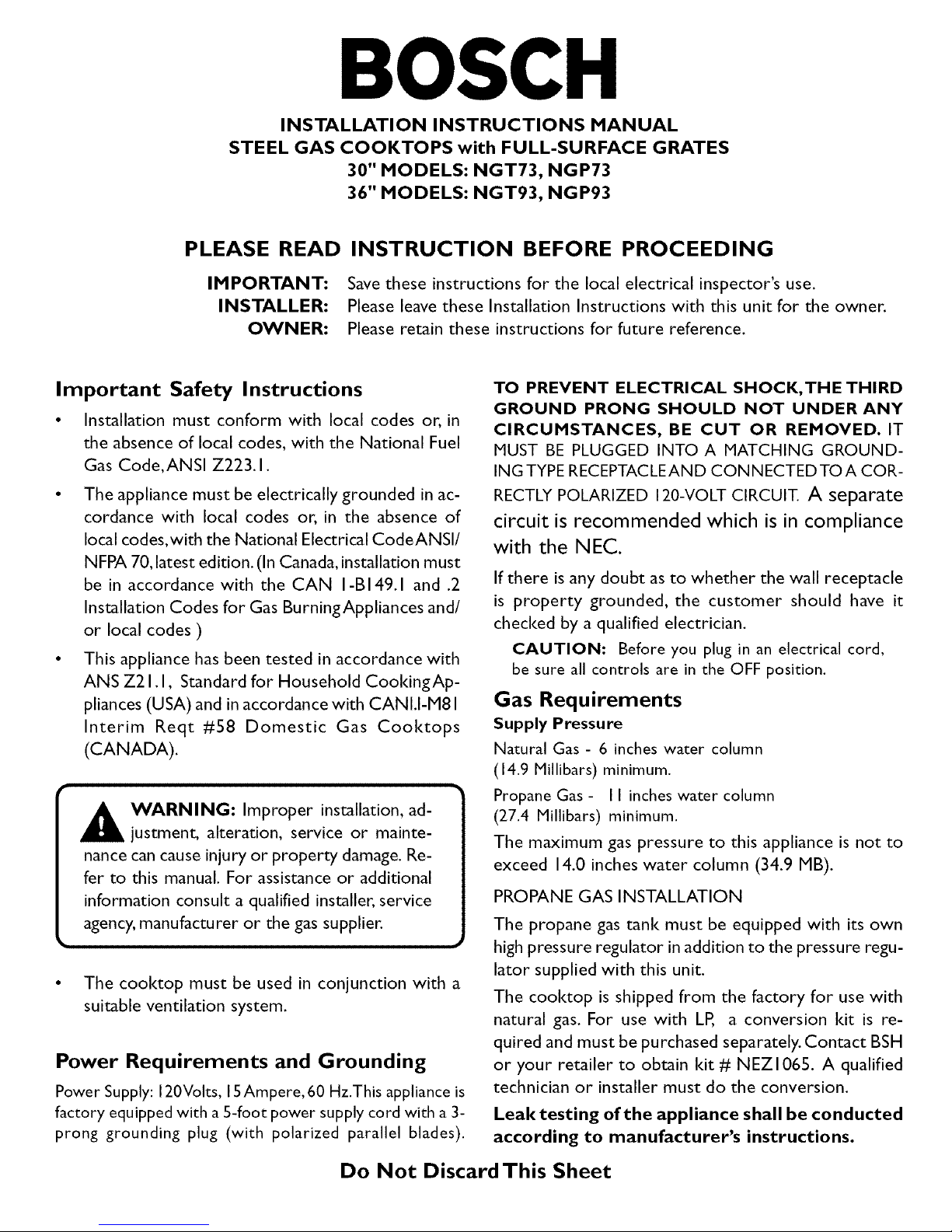
Figure I - Installed Dimensions (from cool<top edges)
Depth from Back Wall
Cabinet !3" Max.
Hood Depth - 24" Max.
Above Counter - 30" Min_to
Combustible Surface
• _ NGT(P)73- 30" Min. . _.
NGT(P)93 - 36" Min. •
÷ Centered Over Cooktop
Left Side 18_"" Rear Wall *1-3/4"
_-M_n. '_ ._ Right Side
3" Min.
Io o IIo o I
0 0
Cool<top to frontofcountertop - I-I/4"minimum
Dimensions are minimum clearances to combustible materials
NOTICE: All measurements
given in Figures I and 2 have to
be precisely followed. If non-
standard cabinets are used,
make sure they are installed with
minimum dimensions shown in
Fig. I and Fig. 2.
Plan the installation of the unit so
that the power cord, gas shut-off
valve and gas pressure regulator are
accessible from the front of cabinet.
Ifa drawer is installed directly under
the cool<top, its depth (front to
bad<) should be no greater than 15".
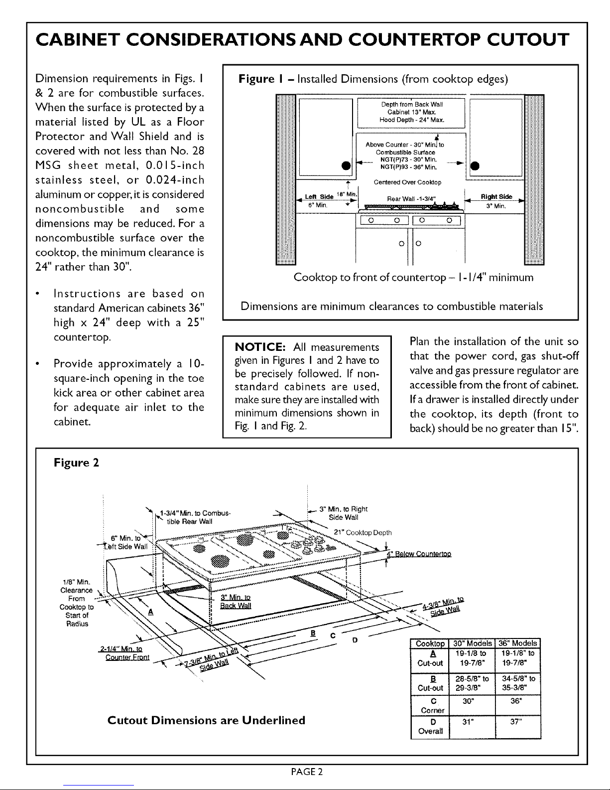
Figure 2
1-3/4" Min, to Combus-
tible Rear Walt
_3" Min, to Right
Side Wail
21" Cooktop Depth
1/8" Min.
Clearance
From
Cooktop to
Start of
Radius
2-1/4" Min. to "_
Cutout Dimensions are Underlined
30" Models 36" Models
A ' 19-1/8 to 19-1/8" to
Cut-out 19-7/8" 19-718"
B 28-5/8" to 34-5/8" to
Cut-out 29-3/8" 35-3/8"
C 30" 36"
Corner
D 31" 37"
Overall
PAGE 2
 Loading...