

Bosch NGMP655 Installation Manual
Gas Cooktops
NGM30, NGM50, NGM56
NGM80, NGM86, NGMP65, NGMP055
Table of Contents
Questions?
1-800-944-2904
www.bosch-home.com
We look forward to hearing from you!
This Bosch Appliance is made by
BSH Home Appliances Corporation
1901 Main St, Suite 600
Irvine, CA 92614
Safety . . . . . . . . . . . . . . . . . . . . . . . . . . . . . . . 1
IMPORTANT SAFETY INSTRUCTIONS . . . . 1
Installation . . . . . . . . . . . . . . . . . . . . . . . . . . . 3
Before You Begin . . . . . . . . . . . . . . . . . . . . . . 3
Tools and Parts Needed . . . . . . . . . . . . . . . . 3
Parts Included . . . . . . . . . . . . . . . . . . . . . . . . 3
General Information . . . . . . . . . . . . . . . . . . . . 3
Preparation . . . . . . . . . . . . . . . . . . . . . . . . . . 3
Installation Procedure . . . . . . . . . . . . . . . . . . 5
Prepare the Countertop . . . . . . . . . . . . . . . . . 5
Seal the Cooktop with Foam Tape . . . . . . . . 5
Install the Cooktop . . . . . . . . . . . . . . . . . . . . . 5
Connect Gas Supply . . . . . . . . . . . . . . . . . . . 6
Connect Electrical Supply . . . . . . . . . . . . . . . 6
Burner Cap Placement . . . . . . . . . . . . . . . . . 7
Install Burner Grates . . . . . . . . . . . . . . . . . . . 8
Final Check . . . . . . . . . . . . . . . . . . . . . . . . . . 9
Service . . . . . . . . . . . . . . . . . . . . . . . . . . . . . 10
Before Calling Service . . . . . . . . . . . . . . . . . 10
Product Data Plate . . . . . . . . . . . . . . . . . . . . 10
9 IMPORTANT SAFETY INSTRUCTIONS
WARNING:
If the information in this manual is not followed exactly, a
fire or explosion may result causing property damage,
personal injury or death.
-- Do not store or use combustible materials,
gasoline or other flammable vapors and liquids
in the vicinity of this or any other appliance.
-- WHAT TO DO IF YOU SMELL GAS
• Do not try to light any appliance.
• Do not touch any electrical switch.
• Do not use any phone in your building.
• Immediately call your gas supplier from a
neighbor’s phone. Follow the gas supplier’s
instructions.
• If you cannot reach your gas supplier, call
the fire department.
-- Installation and service must be performed by a
qualified installer, authorized service agency or
the gas supplier.
READ AND SAVE THESE INSTRUCTIONS
Safety
INSTALLER: LEAVE THESE INSTRUCTIONS WITH THE
APPLIANCE AFTER INSTALLATION IS COMPLETE.
IMPORTANT: SAVE FOR THE LOCAL INSPECTOR'S
USE.
Important Safety Instructions
WARNING:
Do not repair or replace any part of the appliance unless
specifically recommended in the manuals. Improper
installation, service or maintenance can cause injury or
property damage. Refer to this manual for guidance. All
other servicing should be done by a qualified technician.
Gas Appliance Safety
any pressure testing at pressures in excess of ½ psi
(3.5 kPa).
• The appliance must be isolated from the gas supply
piping system by closing its individual manual shutoff
valve during any pressure testing of the gas supply
piping system at test pressures equal to or less than ½
psi (3.5 kPa)
• The minimum supply pressure must be 1" water
column above the manifold pressure printed on the
data plate.
• The maximum supply pressure must not exceed 14.0
inches water column (34.9Millibars).
• For Massachusetts installations:
• Installation must be performed by a qualified or
licensed contractor, plumber or gas fitter qualified
or licensed by the state, province or region where
this appliance is being installed.
• Shut-off valve must be a "T" handle gas cock.
• Flexible gas connector must be new and not longer
than 36 inches.
• Installer - show the owner where the gas shut-off valve
is located.
• Install a gas shutoff valve near the appliance. It must
be easily accessible in an emergency.
• Leak testing must be conducted by the installer
according to the instructions in this manual.
• The appliance and its individual shutoff valve must be
disconnected from the gas supply piping system during
Propane Gas Installation
• The propane gas tank must be equipped with its own
high pressure regulator. In addition, the regulator
supplied with this unit must also be used.
• The appliance is shipped from the factory for use with
natural gas. It must be converted for use with propane.
A qualified technician or installer must do the
conversion.
Equipment and Usage Safety Requirements
• The cooktop must be used in conjunction with a
suitable ventilation system.
• Remove all tape and packaging before using the
appliance. Destroy the packaging after unpacking the
appliance. Never allow children to play with packaging
material.
• Never modify or alter the construction of the appliance.
For example, do not remove panels, wire covers or
screws.
• To eliminate the risk of burns or fire by reaching over
heated surface units, cabinet storage space located
above the surface units should be avoided. If cabinet
storage is to be provided, the risk can be reduced by
English 1

9 IMPORTANT SAFETY INSTRUCTIONS
READ AND SAVE THESE INSTRUCTIONS
installing a hood that projects horizontally a minimum of
5 inches beyond the bottom of the cabinet.
• Verify that cabinets above the cooktop are a maximum
of 13" (330 mm) deep.
Appliance Handling Safety
• Unit is heavy and requires at least two people or proper
equipment to move.
• Hidden surfaces may have sharp edges. Use caution
when reaching behind or under appliance.
Safety Codes and Standards
• This appliance complies with one or more of the
following Standards:
• ANSI Z21.1, Household Cooking Gas
Appliances
• It is the responsibility of the owner and the installer to
determine if additional requirements and/or standards
apply to specific installations.
• Installation must conform with local codes or, in the
absence of local codes, with the National Fuel Gas
Code, ANSI Z223.1/NFPA 54.
• The appliance must be electrically grounded in
accordance with local codes or, in the absence of local
codes, with the National Electrical Code ANSI/ NFPA
70, latest edition. (In Canada, installation must be in
accordance with the CAN 1-B149.1 and .2 Installation
Codes for Gas Burning Appliances and/ or local
codes).
9 WARNING
State of California Proposition 65 Warnings:
This product contains chemicals known to the State
of California to cause cancer, birth defects or other
reproductive harm.
Electric Safety
• Before you plug in an electrical cord, be sure all
controls are in the OFF position.
• For appliances equipped with a cord and plug, do not
cut or remove the ground prong. It must be plugged
into a matching grounding type receptacle to avoid
electrical shock. If there is any doubt as to whether the
wall receptacle is properly grounded, the customer
should have it checked by a qualified electrician.
• This appliance should be installed in accordance with
the National Electric Code or Canadian Electrical
Code. It is required that the cooktop be installed on a
grounded, non-GFCI branch circuit.
• Installer - show the owner the location of the circuit
breaker or fuse. Mark it for easy reference.
• Important - Save these instructions for the local
electrical inspector's use.
• Before installing, turn power OFF at the service panel.
Lock service panel to prevent power from being turned
ON accidentally.
• Be sure your appliance is properly installed and
grounded by a qualified technician. Installation,
electrical connections and grounding must comply with
all applicable codes.
English 2
High Altitude Installation
This range is CSA certified for safe operation up to an
altitude of 10,000 ft without any modifications (except LP
conversion, when applicable). Contact service for use at
altitudes above 10,000 feet.
Installation
Before You Begin
Tools and Parts Needed
1. Phillips Head Screwdriver
2. Drill with 1/4” (6.5mm) bit
3. Tape Measure
4. Teflon Tape (Gas Rated)
5. Adjustable wrench or channel lock pliers
Parts Included
1. Foam tape
2. Hold down brackets (4)
3. Screws, #10-32 x 2 1/2” (63.8mm) (4)
4. Sheet Metal Screws, #8 x 3/8” (9.5mm) (4)
5. Washers (4)
6. Burner Grates (3)
7. Burner Caps
36” models: (5)
30” models: (4) or (5)
8. Pressure Regulator
9. LP Gas Conversion Kit
If parts are missing or damaged, call the number or write to
the address listed inside the back cover.
Preparation
Electrical Requirements
9 CAUTION
Do not use an extension cord with the gas cooktop.
This appliances requires a 60 Hz, 15 Amp, 120 VAC
connection. Plan the installation so that the power
connection is accessible from the front of the cabinet.
Gas Requirements
Supply Pressure:
• Natural Gas - 7 inches water column (14.9 Millibars)
minimum.
• Propane Gas -11 inches water column (27.4 Millibars)
minimum.
The propane gas tank must be equipped with its own high
pressure regulator in addition to the pressure regulator
supplied with this unit. The cooktop is shipped from the
factory for use with natural gas. For use with LP conversion
a qualified technician or installer must do the conversion.
Cabinet Requirements
General Information
Overall Dimensions
30” Models 36” Models
Width
(Side to Side)
Depth
(Front to Back)
Height
(Top to Bottom)
NOTE:
These are overall dimensions NOT cutout dimensions.
31” (788 mm) 37” (940 mm)
21 1/4” (540
mm)
3 13/16 (97 mm) 3 13/16 (97 mm)
21 1/4” (540
mm)
Dimension requirements in Figures 1 and 2 are for
combustible surfaces. When the surface is protected by a
material listed by UL as a Floor Protector and Wall Shield
covered with not less than No. 28 MSG sheet metal 0.015
inch (0.38mm) stainless steel, 0.024 inch (0.6mm)
aluminum or copper, it is considered noncombustible and
some dimensions may be reduced. For a noncombustible
surface over the cooktop, the minimum clearance is 24"
(61cm) rather than 30" (76cm).
• Instructions are based on standard American cabinets
36" high (91cm) x 24" deep (61cm) with a 25" (63cm)
countertop.
• Provide approximately a 10 square inch opening
2
(65cm
adequate air inlet to the cabinet if installed with a
downdraft.
) in the toe kick area or other cabinet area for
English 3
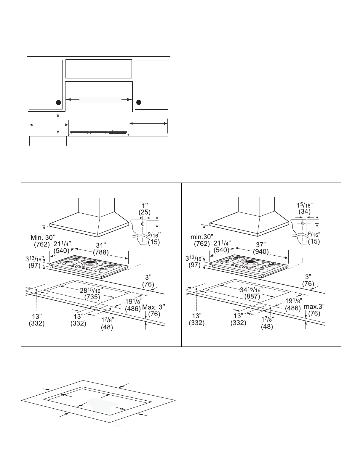
• The maximum depth of cabinet installed above cooktop
Depth from Back Wall
Cabinet 13" (33cm) max.
Hood Depth - 24" (61cm) max.
Centered Over Cooktop
Rear Wall - 2" (5cm)
Right Side
12" (33cm) min.
Left Side
12" (33cm) min.
18" (46cm) min.
Above Counter - 30" (76 cm) min. to
Combustible Surface
NGM30 - 30" (76cm) min.
NGM36 - 36" (91cm) min.
gas
connection
measurement in inches/mm
30” Models
36” Models
2 1/8”
(54)
3”
(76.2)
3”
(76.2)
3 1/8”
(79.4)
measurement in inches/mm
Front
Back
is 13” (33cm).
Figure 1: Installed Dimensions (from cooktop edges)
Countertop Requirements
NOTE:
All measurements given have to be precisely followed. If
nonstandard cabinets are used, make sure they are
installed with minimum dimensions shown in figure 1 and
figure 2.
Plan the installation of the unit so that the power cord, gas
shut-off valve and gas pressure regulator are accessible
from the front of cabinet.
Island Installation Mounting Requirements
English 4
gas
connection
measurement in inches/mm
Figure 2: Cutout Dimensions
Use the mounting brackets supplied. See “Install the
Cooktop” on page 5 for further details.
Ventilation Recommendations
We strongly recommend the installation of a ventilation
hood above this appliance. The hood must be installed
according to instructions furnished with the hood.
Note: The appliance should not be installed with a
Heat Reflective Tape
Cutout shows location
of Aluminum Reflective Tape
Section "A - A"
A
A
Cutout
Foam
Ta pe
Rough-in Box
Foam
Tap e
(Seal)
Adjusting
Screw
Adjusting
Screw
Clamp
Clamp
Wooden Block
(to be used with
solid surfacing
material, i.e.
Surell™ and
Corian®)
ventilation system that blows air downward toward the
burners. This type of ventilation system may cause ignition
and combustion problems with the gas cooking appliance
resulting in personal injury or unintended operation.
Installation Procedure
9 WARNING
To avoid electrical shock hazard, before installing
the cooktop, switch power off at the service panel to
prevent the power from being switched on
accidentally.
Prepare the Countertop
Cut out the countertop per the dimensions shown in
“Cabinet Requirements” on page 3.
Some solid surface materials, such as Surell™ and
Corian®, require different cutting methods. Consult with the
solid surface manufacturer for the correct cutting method
needed. Apply heat reflective tape such as Scotch
Aluminum Foil Tape #425 or #427 (not included) around the
cutout so that it folds over on the top and sides. Do not
wrap the tape underneath the cooktop. Be sure the tape
extends beyond the outermost flange of the cooktop. All
corners should be covered with tape.
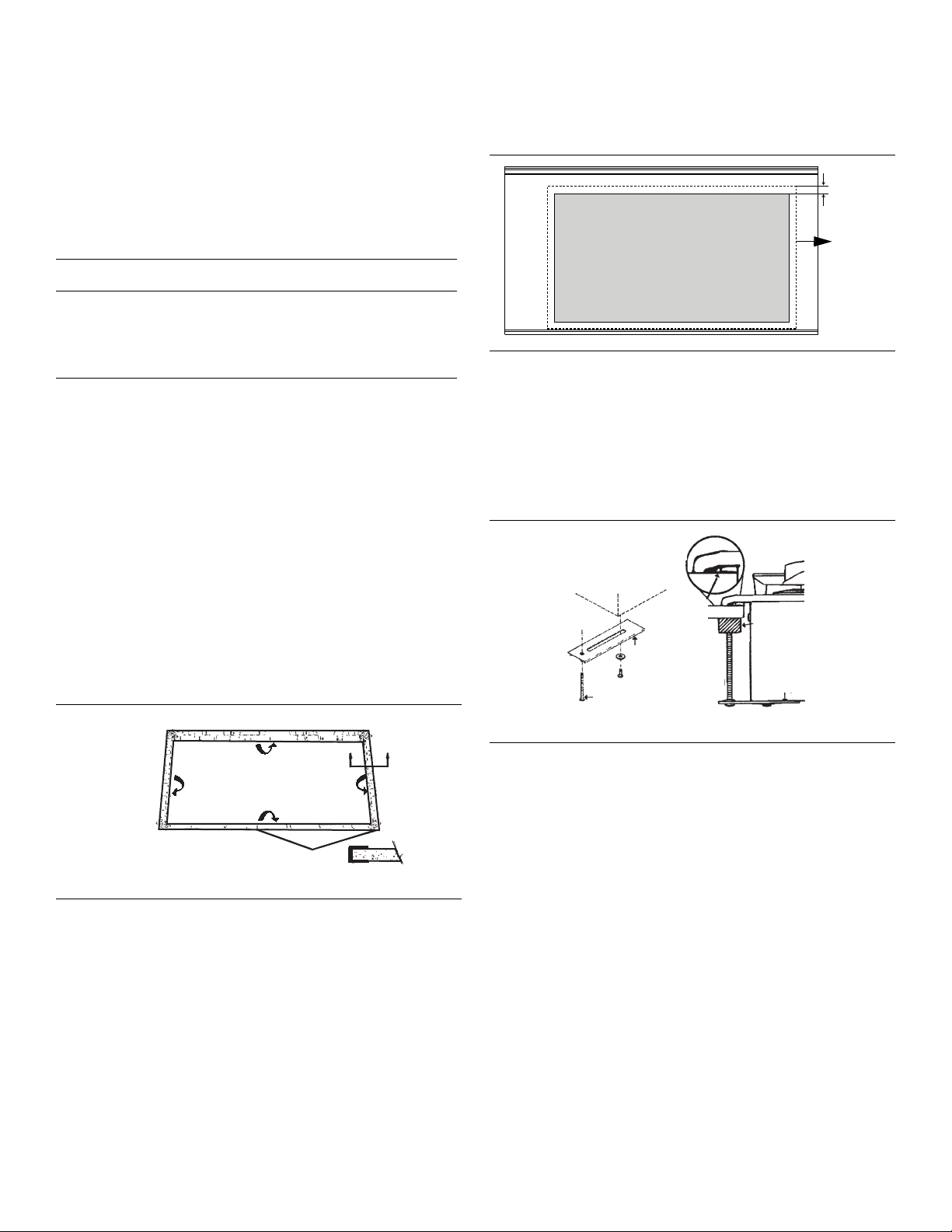
cutout as shown by the dotted line in Figure 4: “Counter
Cutout – Foam Tape Placement”. Leave 1/4” (6.35mm) gap
between the foam tape and the edge of the cutout.
1/4”
(6.35mm)
Figure 4: Counter Cutout – Foam Tape Placement
Install the Cooktop
Insert cooktop into the cutout. Attach clamps of the holddown brackets packaged with the cooktop to the rough-in
box. Use the washer and screws provided.
Figure 3: Counter Cutout – Solid Surface Countertops
Seal the Cooktop with Foam Tape
Apply the self adhesive foam tape in one continuous
rectangle directly to the counter around the perimeter of the
Figure 5: Attaching Hold-Down Brackets
Adjust hold-down brackets to desired position and tighten
screws to rough-in box. Insert adjusting screw into clamp
and secure cooktop to countertop.
NOTE:
For solid surface material installations: Insert a wooden
block between the end of the screw and the bottom of the
countertop. Do not overtighten adjusting screw. Trim
excess aluminum tape around cooktop flange.
English 5
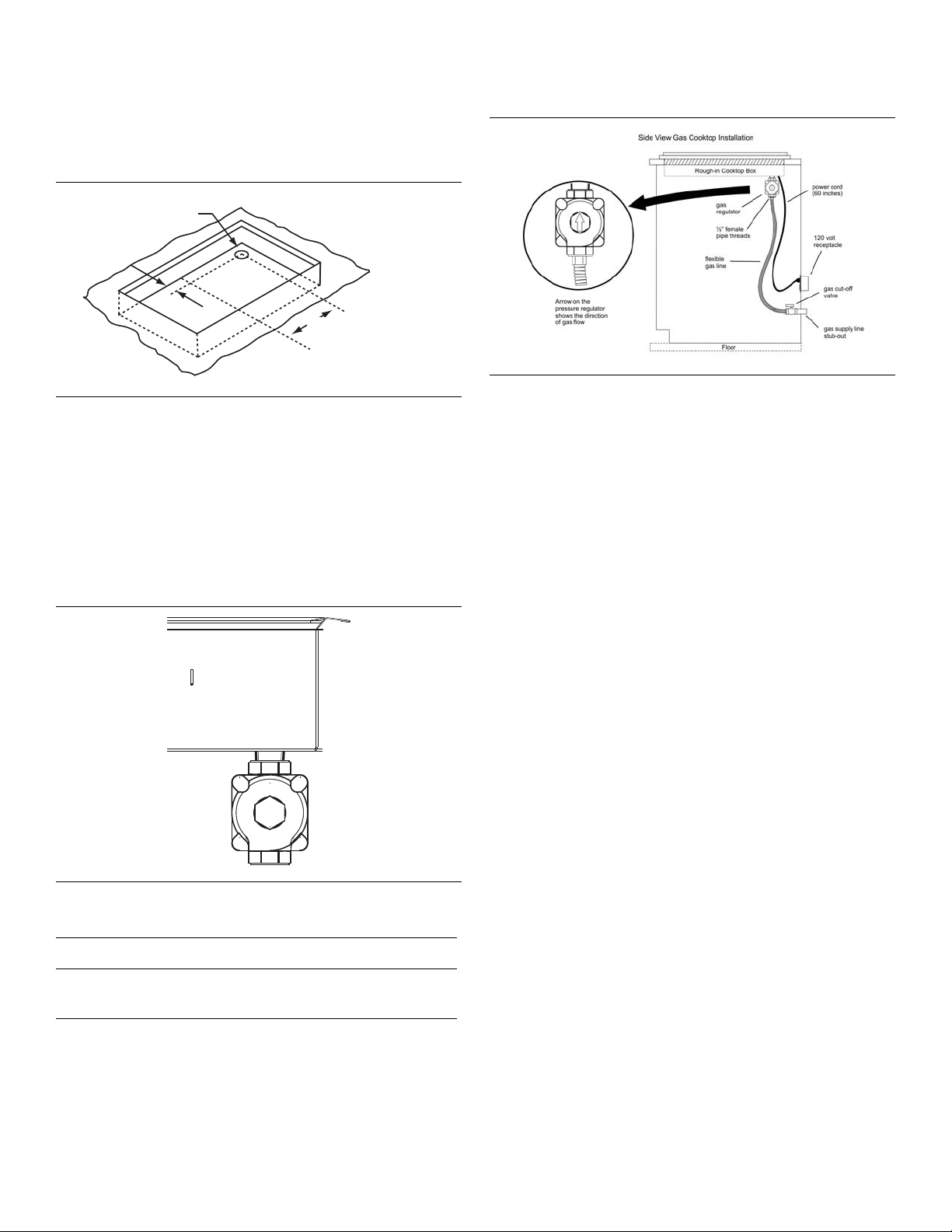
Connect Gas Supply
The gas inlet to the unit is located at the right rear of roughin box.
Opening for Gas
Connection and
Electrical Cord
1”
C of Cutout
L
for 30” models: 12 15/16” (313 mm)
for 36” models: 15 15/16” (389 mm)
Figure 6: Rough-in Box Area
Install the pressure regulator (supplied with unit) to
manifold pipe using Teflon tape on threads of manifold
pipe. Turn to hand tighten plus 1/4 turn, not exceeding 1
turn for alignment. To prevent possible damage to the gas
pressure regulator, install it after the rough-in box is in its
permanent position. When the regulator is securely
installed on the manifold pipe, the conversion nut will be
easily accessible.
Figure 8: Gas and Electrical Location
Check supply line connections for leaks using a soap
solution. Do not use a flame of any sort.
1. Turn on gas.
2. Apply a non-corrosive leak detection fluid to all joints
and fittings in the gas connection between the shut-off
valve and the range. Include gas fittings and joints in
the range if connections may have been disturbed
during installation. Bubbles appearing around fittings
and connections indicate a leak.
3. If a leak appears, turn off supply line gas shut-off valve
and tighten connections.
4. Retest for leaks by turning on the supply line gas shutoff valve. When leak check is complete (no bubbles
appear), test is complete.
5. Wipe off all detection fluid residue.
Figure 7: Pressure Regulator
9 WARNING
Do not attempt any adjustment of the pressure
regulator, except conversion to propane..
Connect the gas supply line to the unit pressure regulator
using a 1/2" flex gas line connector between manual shutoff valve and pressure regulator. Always use a new flex
line.
English 6
Important Notes for Gas Connection:
• The appliance and its individual gas shutoff valve must
be disconnected from the gas supply piping system
during any pressure testing of that system at test
pressures in excess of 1/2 psig (3.5kPa).
• The appliance must be isolated from the gas supply
piping system by closing its individual manual shut-off
valve during any pressure testing of the gas supply
piping system at test pressures equal to or less than 1/
2 psi (3.5kPa).
Connect Electrical Supply
Before connecting 5-foot (1.5 m) supply cord to wall
receptacle, make certain that gas shutoff valve and all
burner controls are in OFF position.
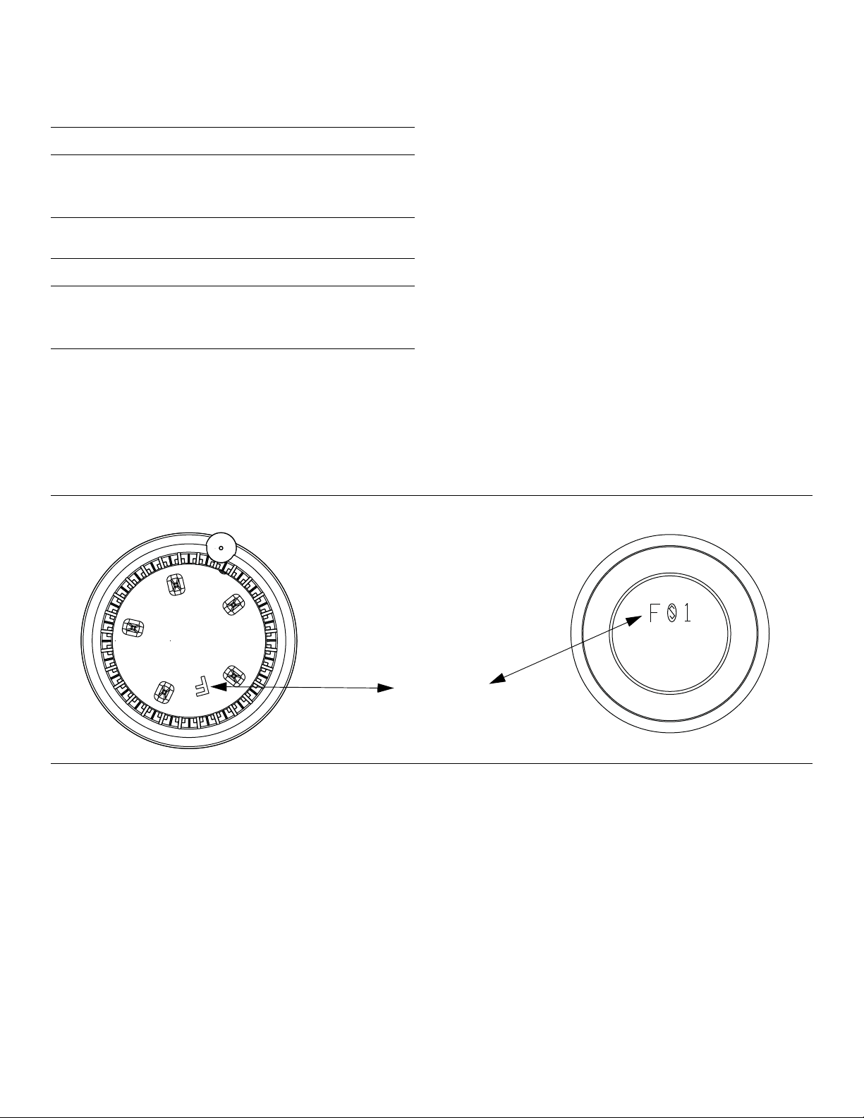
Burner Cap Placement
Burner Base
Burner Cap
Matching letter
designation.
9 WARNING
To prevent flare-ups, do not use the cooktop without
all burner caps and all burner grates properly
positioned.
9 WARNING
• Burner flames are too high.
• Flames shoot out of burners.
• Burners do not ignite.
• Burner flames light unevenly.
• Burner emits gas odor.
Placing Burner Caps
Each cap has a letter (A, D, or F) cast in the underside of
the cap that corresponds to a letter (A, D, or F) cast in the
burner base that is attached to the appliance.
To prevent burns, do not touch burner caps or
grates while hot. Turn the cooktop off and allow the
burners to cool.
Do not attempt any adjustment of the pressure regulator,
except conversion to propane.
The burner caps must be properly placed for the cooktop to
function properly. If the burner cap is not properly placed,
one or more of the following problems may occur:
• After electrical connection is complete, place each
burner cap on its correct burner base per its
corresponding letter designation. See figure “Burners
Caps” on page 7.
• Place burner cap gently on top of base so that the
prongs of the burner base fit snugly into the groove of
the burner cap.
Figure 9: Burners Caps
English 7
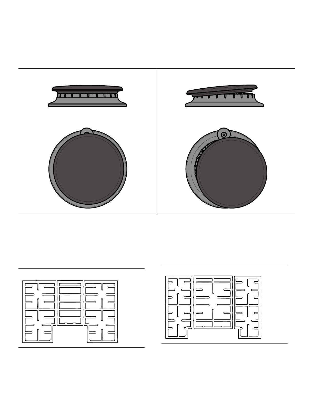
Checking Burner Cap Placement
Correct Burner Cap Placement
Incorrect Burner Cap Placement
30” 4 Burner
30” 5 Burner
• Check to make sure there is not gap between the
burner cap and burner base. See figure “Burner Cap
Placement” on page 8 to see the correct and incorrect
placements of the burner cap.
• You may gently try to move the burner cap from side to
side to check if it is properly placed. If properly placed,
the cap will click from side to side as the prongs hit the
groove ridge.
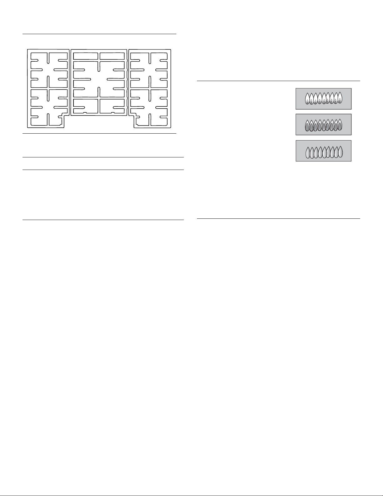
Install Burner Grates
Properly position and install each burner grate as shown in the following illustrations. The center grate will seat with rubber
feet fitting to indentatations in the cooktop surface. Check to be sure the feet match the indentations.
Figure 10: Burner Cap Placement
English 8
9 WARNING
36” 5 Burner
Yellow Flames:
Further adjustment is required.
Yellow Tips on Outer Cones:
Normal for LP Gas.
Soft Blue Flames:
Normal for Natural Gas.
If the flame is completely or
mostly yellow, verify that the regulator is set for the
correct fuel. After adjustment, retest.
Some yellow streaking is normal during the initial startup. Allow unit to operate 4-5 minutes and re-evaluate
before making adjustments.
To prevent flare-ups, properly support pots, and
avoid spills, all grates must be properly positioned
on the cooktop whenever the cooktop is in use.
Each of the four feet must be placed into the
corresponding dimples in the cooktop. Do not use a
grate if the rubber feet are missing or damaged.
Final Check
Check operation of electric igniters. Check flame
characteristics. Flame should be blue with no yellow tip.
For replacement rubber feet: Part # 416438, contact your
dealer or call the service number listed inside the cover.
Figure 11: Checking Flame Characteristics
English 9
 Loading...