How it Works
Log In / Sign Up
Buy Points
How it Works
FAQ
Contact Us
Questions and Suggestions
Users
Bosch
Loading...
N
NGM5624UC
5
NGM5624UC/01
2
NGM5624UC/03
2
NGM5654UC
5
NGM5654UC/01
2
NGM5654UC/03
2
NGM5654UC/04
2
NGM5655
2
NGM5655UC
8
NGM5655UC/01
3
NGM5656UC
10
NGM5664UC
5
NGM5664UC/01
2
NGM5664UC/03
2
NGM5664UC/04
2
NGM80
2
NGM8046UC
5
NGM8054UC
5
NGM8054UC/01
2
NGM8054UC/03
2
NGM8055
2
NGM8055UC
6
NGM8055UC/01
3
NGM8055UC/02
3
NGM8056UC
10
NGM8057UC
6
NGM8065
2
NGM8065UC
7
NGM8065UC/01
3
NGM8065UC/02
3
NGM86
2
NGM8646UC
8
NGM8654UC
5
NGM8654UC/01
2
NGM8654UC/02
3
NGM8654UC/03
2
NGM8654UC/04
2
NGM8655
2
NGM8655UC
7
NGM8655UC/01
3
NGM8656UC
6
NGM8657UC
7
NGM8665
2
NGM8665UC
8
NGM8665UC/01
3
NGMP055
3
NGMP055UC
6
NGMP055UC/01
3
NGMP055UC/02
3
NGMP056UC
6
NGMP077UC
5
NGMP65
2
NGMP655
3
NGMP655UC
6
NGMP656UC
6
NGMP677UC
5
NGP
4
NGP73
5
NGP732UC
3
NGP732UC/01
2
NGP735UC
3
NGP735UC/01
2
NGP736UC
2
NGP736UC/01
2
NGP742UC
NGP745UC
3
NGP746UC
3
NGP93
5
NGP932UC
2
NGP932UC/01
2
NGP935UC
NGP935UC/01
2
NGP936UC
3
NGP936UC/01
2
NGP942UC
3
NGP945UC
3
NGP946UC
2
NGP946UC/01
2
NGT
4
NGT612
2
NGT612PTR
NGT612RIL
NGT612RNE
NGT612TNE
NGT612TTR
NGT615G
NGT615RIL
NGT615RNE
NGT615TFF
NGT615TNE
NGT615TRO
NGT615TTR
NGT622PTR
NGT635RBY
NGT635RIL
NGT635RNE
3
NGT635RPL
2
NGT635STR
NGT635TFF
NGT635TNE
2
Loading...
Loading...
Nothing found
NGMP077UC
Installation manual
32 pgs
2.62 Mb
0
Specs
3 pgs
1.94 Mb
0
User Manual
48 pgs
3.49 Mb
0
Further installation information
2 pgs
615.17 Kb
0
Further installation information
2 pgs
1.41 Mb
0
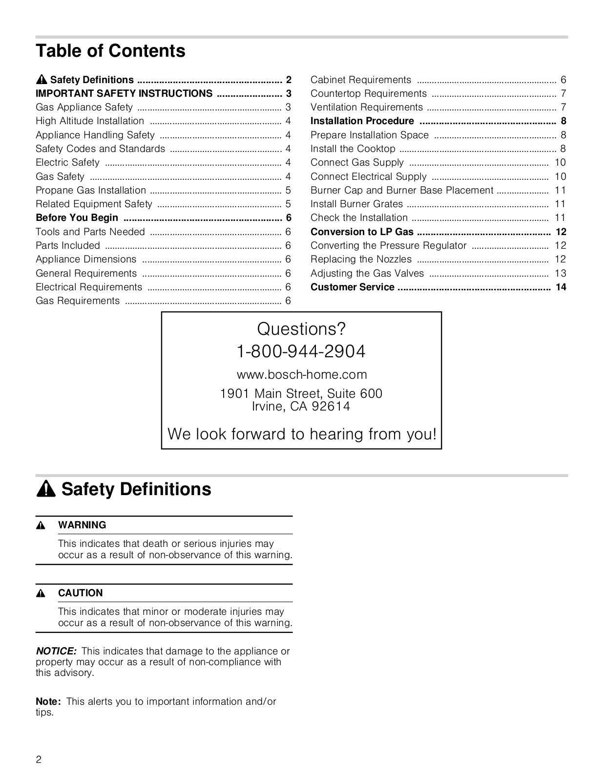
Table of contents
Loading...
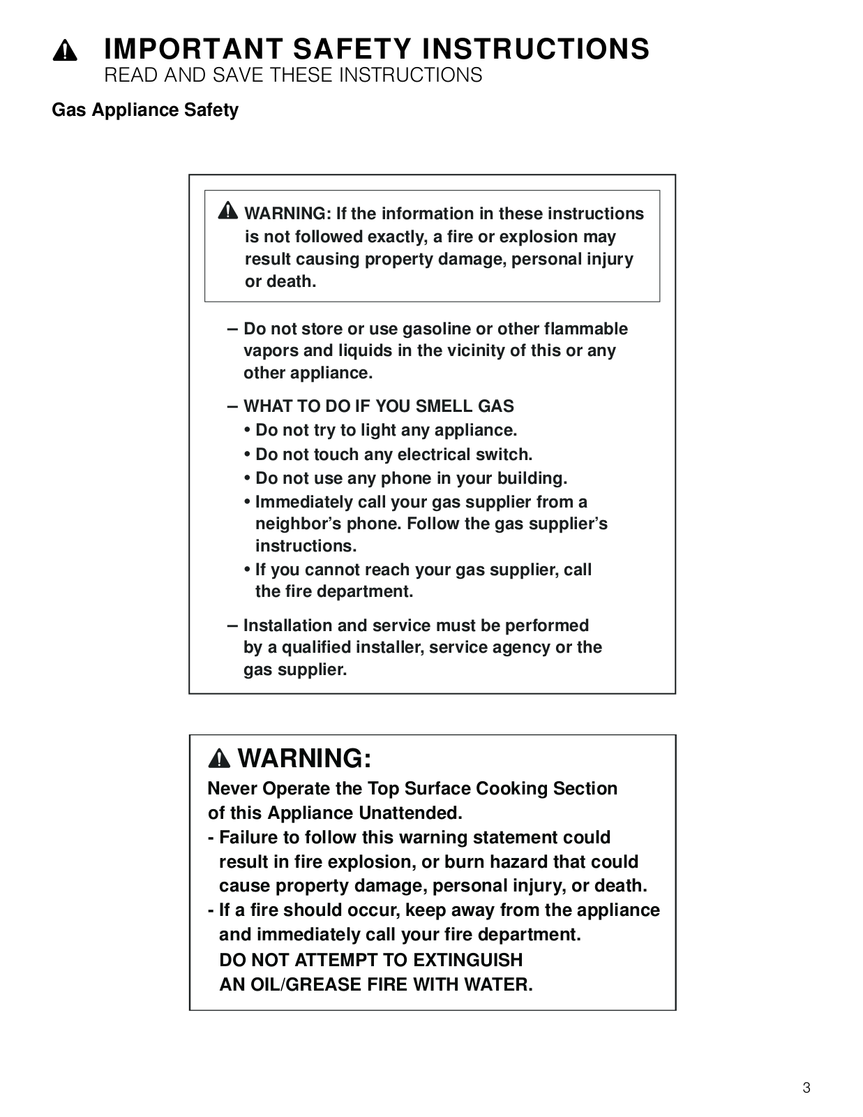
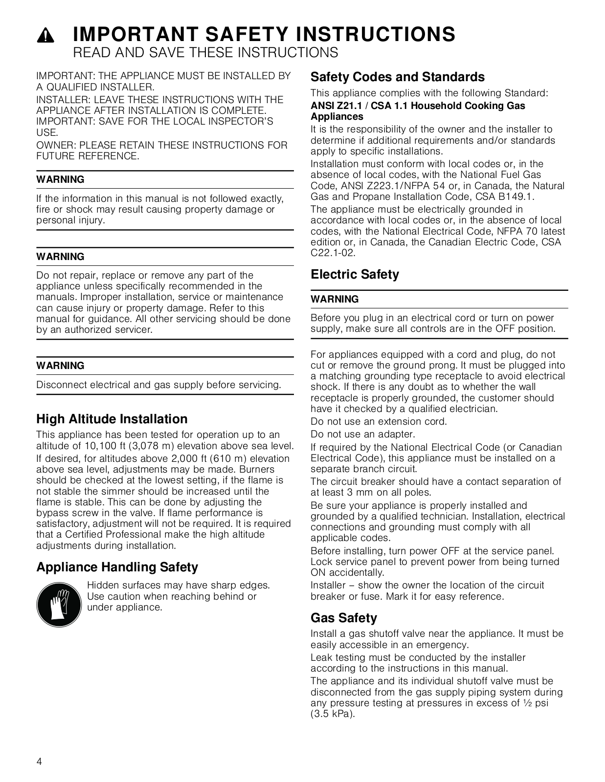
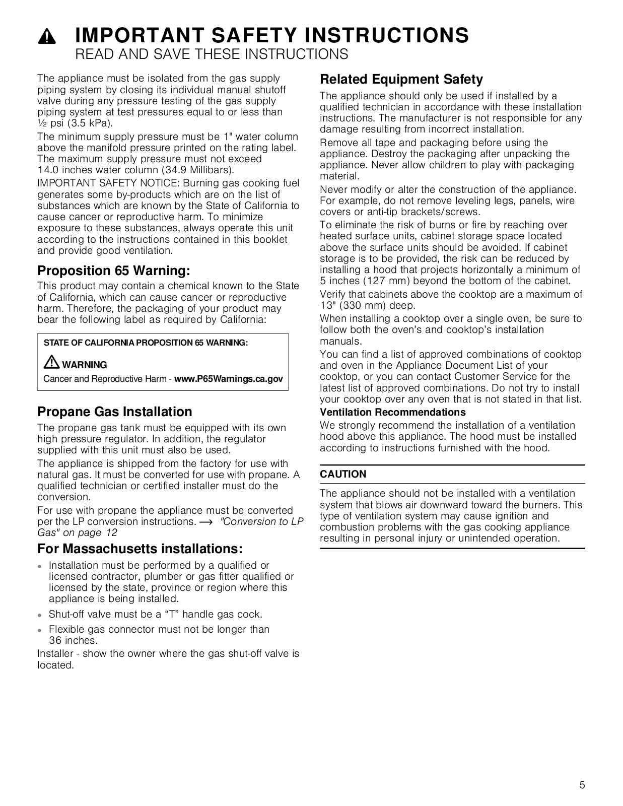
Bosch NGMP077UC Installation manual
...
Bosch Installation manual
Download
Specifications and Main Features
Frequently Asked Questions
User Manual
Download
Loading...
+
22
hidden pages
Unhide
You need points to download manuals.
1 point = 1 manual.
You can buy points or you can get point for every manual you upload.
Buy points
Upload your manuals