

Page 1
Configuration Manager 1.6
en Manual
Page 2

Page 3

Configuration Manager 1.6 Table of Contents | en 1
Table of Contents
1 Introduction 3
1.1 About this manual 3
1.2 Conventions in this manual 3
1.3 System requirements 4
1.4 Configuration Manager 5
1.5 Additional documentation 7
2 Installation and Starting 9
2.1 Installation 9
2.2 Starting the program 9
3Operation 11
3.1 The user interface 11
3.2 Main tabs: Network, Devices, and Cameras 17
3.3 The System main tab 21
4 Working with the Configuration Manager 23
4.1 Settings 23
4.2 Basic functions 30
4.3 Working with BVIP software and firmware modules 43
Bosch Security Systems Operator’s Manual A1 | 2007.05
Page 4

2 en | Table of Contents Configuration Manager 1.6
A1 | 2007.05 Operator’s Manual Bosch Security Systems
Page 5

Configuration Manager 1.6 Introduction | en 3
1 Introduction
1.1 About this manual
This manual is intended for persons responsible for configuring
and managing a CCTV system. This manual describes how to
use the Configuration Manager 1.6 program.
This document assumes that the reader is familiar with both the
CCTV system and the other programs that are integrated into
the system.
1.2 Conventions in this manual
In this manual, the following symbols and notations are used to
draw attention to special situations:
CAUTION!
!
i
Security instructions where non-compliance can result in loss
of data are marked with this symbol.
NOTICE!
This symbol indicates special features and provides tips and
information for easier, more convenient use of the software.
Terms that you can find in the program, such as menu options
or commands, are written in bold.
Bosch Security Systems Operator’s Manual A1 | 2007.05
Page 6

4 en | Introduction Configuration Manager 1.6
1.3 System requirements
Operating system: Windows XP Home
Windows XP Professional
Windows 2003 Server
CPU: Pentium IV, 2.0 GHz or faster
RAM: 256 MB or more
Graphics card: NVIDIA GeForce 6600
NVIDIA Quadro FX 1400ATI RADEON X600/
X800
or better
Screen resolution: 1280 x 1024 pixels
Sound card: recommended
Network adapter: 100 Mbps
Software: DirectX 9.0c
Hard drive space:
(for installation)
45 MB
(.NET environment, Configuration
Manager)
A1 | 2007.05 Operator’s Manual Bosch Security Systems
Page 7

Configuration Manager 1.6 Introduction | en 5
1.4 Configuration Manager
The Configuration Manager 1.6 provides the following features
(the availability of these depends on the environment in which
the program is used):
– Network Scan
This function automatically detects all compatible devices
in a network, such as video senders (e.g. VIP X1600), video
receivers (e.g. VIP XD) or NVRs.
– Device information and configuration
Comparable with the Web browser view, the Configuration
Manager shows the current configuration for each device
and allows you to change the settings.
– Multiple configuration
You can use the Configuration Manager to make individual
settings for multiple devices simultaneously (e.g. time
settings), allowing you to configure large systems more
quickly.
– Device system integration
You can use the Device allocator in the Configuration
Manager to make devices accessible for use with the
VIDOS Lite Viewer or the Archive Player.
– Basic configuration for BVIP programs
For certain BVIP programs (Bosch Video over IP),
fundamental system settings are made using the
Configuration Manager.
– Access to license management
Firmware modules requiring a license, such as IVMD
(Intelligent Video Motion Detection), are set up using the
Configuration Manager.
– Work offline
The Configuration Manager allows you to make settings for
selected devices offline. When in operation, the
configuration data of the devices is transferred to your
computer where it can be edited offline.
Bosch Security Systems Operator’s Manual A1 | 2007.05
Page 8

6 en | Introduction Configuration Manager 1.6
This functionality can also be used to back up the
configuration data of the devices locally. If, for example, a
device needs to be replaced by another of the same type,
this data can then be transferred to the new device.
This functionality is extended with the Replacement
command. Replaced devices are detected and automatic
configuration is possible thanks to the saved data.
– Simpler access to devices
The Snapshot scan gives an overview of all the cameras
that provide video data. The snapshots can be used to
identify the camera and device, and give you direct access
to said camera or device.
A1 | 2007.05 Operator’s Manual Bosch Security Systems
Page 9

Configuration Manager 1.6 Introduction | en 7
1.5 Additional documentation
Once the Configuration Manager 1.6 has been installed, this
document is also available as online help within the program.
Depending on the configuration of your system, the following
documentation may also be useful:
Camera documentation The manufacturer will provide you
with separate documentation for
each camera.
VideoJet, VIP etc.
NVR
VIDOS
VIDOS Server
Archive Player
VIDOS Monitor Wall
VRM
IVMD
and other BVIP software
Bosch will provide you with
documentation for each device.
This explains the typical device
settings.
Bosch will provide you with
separate documentation for each
of these software products.
Bosch Security Systems Operator’s Manual A1 | 2007.05
Page 10

8 en | Introduction Configuration Manager 1.6
A1 | 2007.05 Operator’s Manual Bosch Security Systems
Page 11

Configuration Manager 1.6 Installation and Starting | en 9
2 Installation and Starting
2.1 Installation
The Configuration Manager is automatically part of the
installation for all BVIP programs that require it for
configuration purposes.
Each device that can be set up using the Configuration Manager
is supplied with a CD on which you will find the installation file
for the Configuration Manager.
You can install the Configuration Manager on as many
computers running Microsoft Windows as you wish.
2.2 Starting the program
After successful installation, you will find the following icon on
your desktop:
Double click this icon to start the program.
The Configuration Manager can also be called up from the Start
menu. Several BVIP programs enable you to start the
Configuration Manager directly within the relevant program.
Operation of the Configuration Manager varies according to the
context in which it is being used. In some cases, it is merely a
tool that enables you to configure BVIP devices more
conveniently and more comprehensively. For certain BVIP
programs and firmware modules, however, the Configuration
Manager is indispensable, as it is the only way to set these up.
You can obtain additional information here: Abschnitt 4 Working
with the Configuration Manager, Seite 23.
Bosch Security Systems Operator’s Manual A1 | 2007.05
Page 12

10 en | Installation and Starting Configuration Manager 1.6
A1 | 2007.05 Operator’s Manual Bosch Security Systems
Page 13
Configuration Manager 1.6 Operation | en 11
3 Operation
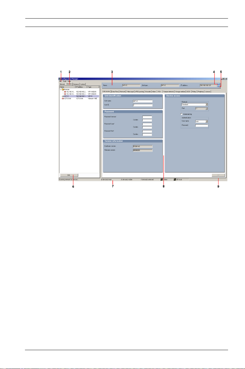
3.1 The user interface
No. Explanation
1 Main menu
2 Main tabs: Network, Devices, System (and Cameras)
3Info bar
4 Device information
5Live video
6 Additional functions
7 Status bar
8 Display area
View changes according to selection in main tab
9Set
Below, you will find more detailed information about the
program's general user interface.
Bosch Security Systems Operator’s Manual A1 | 2007.05
Page 14

12 en | Operation Configuration Manager 1.6
The main tabs are explained in detail in separate sections:
– Abschnitt 3.2 Main tabs: Network, Devices, and Cameras,
Seite 17
You can choose to show or hide the Cameras main tab.
The display area for each main tab contains a series of tabs
through which the selected devices can be configured.
– Abschnitt 3.3 The System main tab, Seite 21
Here, you can make basic settings for the Configuration
Manager itself and other BVIP programs.
3.1.1 Main menu
Menu option Task
File Connect to
server…
Disconnect from
server
Work offline
Work online
Close The Configuration Manager program is
Connects the Configuration Manager to
a VIDOS Server. This allows you to set
up a server and configure a client/
server system. For more details, refer
to the VIDOS Server documentation.
The connection between the
Configuration Manager and a VIDOS
Server is broken.
The settings for selected devices can
be made offline while the device
remains in operation. For this purpose,
the configuration files of the devices
are backed up locally on your
computer. You can edit the data and
send it back to the devices at a later
stage.
closed. This also breaks the connection
between the Configuration Manager
and the server.
A1 | 2007.05 Operator’s Manual Bosch Security Systems
Page 15

Configuration Manager 1.6 Operation | en 13
Menu option Task
Tools Logging... Displays the Device communication
log dialog box.
Here, you can view the RCP+
commands that are transmitted by the
Configuration Manager, Archive Player,
VIDOS Lite Viewer and VIDOS Server
when connecting to devices, if you
have enabled logging.
Device allocator… Displays the Device allocator dialog
box.
If VIDOS is being used, it is not
possible to allocate devices – devices
are allocated to the VIDOS system with
VIDOS.
Snapshot scan… Displays a window in which a snapshot
for each of the connected cameras is
displayed. The popup menu of the
snapshots gives you access to the
settings relevant for the device. The
device can be added to the system.
Archive Player…
Monitor Wall…
VIDOS…
Other software components can be
started directly.
The prerequisite for this is that the
relevant program is installed on the
same PC.
Bosch Security Systems Operator’s Manual A1 | 2007.05
Page 16
14 en | Operation Configuration Manager 1.6
Menu option Task
Help Index Displays the online help.
About… Displays the About Configuration
Manager dialog box, which contains
information about:
– The Bosch software components
installed on this PC
– The software version numbers of
the installed components
– The language in which the
programs are currently displayed,
and information about where the
system files are stored
– The licenses currently available on
this PC Licenses
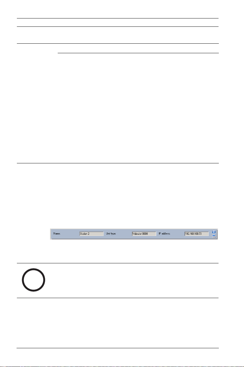
3.1.2 Info bar
When one of the Network, Devices or Cameras main tabs is
opened, an info bar appears above the display area. This info
bar provides you with brief information about each device you
select in the main tab. In addition, you can use the two icons on
the right-hand edge of the bar to open further windows
containing additional information:
The name, the unit type and the IP address of the selected
device are shown.
NOTICE!
If several devices are selected, all fields contain the entry
i
A1 | 2007.05 Operator’s Manual Bosch Security Systems
<multiple> and you cannot open any additional windows with
the Device info and Live video icons.
Page 17

Configuration Manager 1.6 Operation | en 15
Click Device info:
This opens up a window that contains detailed information
about the selected device:
Click Live video:
You will see a dialog box showing live video picture from the
camera connected to the selected device.
Choose whether the images should be displayed here in video
format (MPEG) or as continuously updated snapshots (JPEG).
If you have selected JPEG, you can specify how frequently the
snapshots are refreshed. If you set the period to 0 seconds, the
preview screen is not refreshed.
You can select whether the display is Small or Large.
Bosch Security Systems Operator’s Manual A1 | 2007.05
Page 18

16 en | Operation Configuration Manager 1.6
3.1.3 Status bar
The status bar at the bottom edge of the window shows the
following:
– In the left-hand section: whether or not a network scan is
currently in progress.
– In the central section: the number of detected, visible and
selected devices.
– In the right-hand section: whether you are currently
working Online or Offline and whether or not the
Configuration Manager is currently connected to a server.
If it is connected to a server, the server IP address is
displayed. Otherwise the entry DB local appears here.
A1 | 2007.05 Operator’s Manual Bosch Security Systems
Page 19

Configuration Manager 1.6 Operation | en 17
3.2 Main tabs: Network, Devices, and Cameras
These main tabs are used to configure devices and therefore
have a very similar structure. They each show a device list that
can be generated in various ways:
–The Network main tab shows all BVIP devices supported
by the Configuration Manager that are detected in the
network scan.
–The Devices main tab shows all devices that have
previously been manually allocated to the system.
– You can choose to display the Cameras main tab. This
shows the cameras that are connected to devices that
have been manually allocated to the system.
NOTICE!
If you are working with VIDOS, allocation to the system is
i
carried out in VIDOS. Manual allocation with the Configuration
Manager is not possible in this instance.
Icons are displayed in front of the listed devices to indicate the
device status. In the Network and Devices main tabs, the
standard icon is a server; in the Cameras tab, it is a camera.
However, additional graphics are identical:
Device/camera is available.
Network tab: there is communication with the device.
Devices tab: device is allocated to the system.
Cameras tab: camera is available in the system.
Device/camera is offline.
A red cross indicates devices with which communication is not
possible. For example, these could be devices for which the
power supply has been interrupted.
Device/camera is password-protected.
Devices that are password-protected are indicated by a
padlock, until you have authenticated yourself for the device.
Device/camera is password-protected and offline.
Additional information about the devices can be seen if you
scroll to the right.
Bosch Security Systems Operator’s Manual A1 | 2007.05
Page 20

18 en | Operation Configuration Manager 1.6
3.2.1 Popup menu
Right-click a device to open the popup menu. If you have
selected multiple devices, not all options in the popup menu
are active.
The following table provides an overview of the commands:
Command Action
Add to system…
(Network main tab)
Select group
(Devices and Cameras
main tabs)
New device…
(Devices main tab)
Delete
(Devices main tab)
Set session
authentication…
The selected device is allocated to the system.
Before making an allocation, you can select a
group or create a new one.
This command corresponds to the Device
allocator dialog box.
(Details: Abschnitt 4.2.4 Device allocator,
Seite 32)
If several devices have been grouped, you can
use this option to select all devices or cameras
of that group for editing.
You can allocate a non-listed device to the
system. This menu option is only active if you
click the area in the main tab in which no
devices are listed.
The selected device is deleted from the system.
If a selected device is protected by a password,
you must authenticate yourself for that device.
In the Session authentication dialog box, enter
your password for one of the user levels (user,
live, service).
Any fields you are not authorized to change
remain marked by a padlock and are blocked
for editing.
A1 | 2007.05 Operator’s Manual Bosch Security Systems
Page 21

Configuration Manager 1.6 Operation | en 19
Command Action
Firmware upload… You can select the desired upload file and start
the upload. Refer to the information about
firmware uploads in the documentation for the
relevant device.
This command can also be used to perform a
firmware upload for several devices
simultaneously – make sure that all of the
selected devices are of the same device type.
Settings Download…
Configuration data of the selected devices is
saved on your computer for offline editing.
Upload…
The configuration data that was edited offline
is sent to the selected devices. Once the
upload has been successfully completed, the
device operates according to the new
configuration data.
(Details: Abschnitt 4.2.8 Work offline, Seite 39)
Replacement… (only in the Devices main tab)
Configuration data of replaced devices is
automatically replaced with locally stored data
of a device of the same type.
(Details: Abschnitt 4.2.9 Replace, Seite 41)
Unit
network settings…
You will see the Network settings dialog box.
Use this dialog box to change the IP address,
subnet mask and gateway of the selected
device.
This is only possible for devices that are not
password-protected.
Show live video… The live video for the cameras connected to the
device is shown.
Show in Web browser… The livepage of the Web browser view for the
device is opened in the default browser.
This option is not available for VIDOS Server.
Bosch Security Systems Operator’s Manual A1 | 2007.05
Page 22

20 en | Operation Configuration Manager 1.6
Command Action
Show settings in Web
browser...
Device info… The dialog box containing device information is
Blink power
LED
Reset Initiates a reboot of the device. This is only
The configuration page of the Web browser
view for the device is opened in the default
browser.
This option is not available for VIDOS Server.
displayed.
The power LED on the device flashes. This
allows you to check whether there is any
communication between the Configuration
Manager and the device. This command also
helps you to identify a device if several devices
of the same type are installed at the same
location.
possible for devices that are not passwordprotected.
3.2.2 The view window
The view window for the Network, Devices and Cameras main
tabs shows a series of tabs, the number and content of which
depend on the device selected in the list.
The tabs can be used to make the configuration settings that
the device also provides in the Web browser view, some of
them with a slightly different composition:
NOTICE!
Detailed information about the configuration options for a
i
A1 | 2007.05 Operator’s Manual Bosch Security Systems
device can be found in the relevant device documentation and
the online help in the relevant Web browser view.
Page 23

Configuration Manager 1.6 Operation | en 21
3.2.3 Blocked input fields
It is possible that some fields are blocked for editing. The
causes for the block are indicated by different entries in the
fields:
If several devices are selected, some settings
cannot be made. The input fields are marked with
a padlock.
If a device is currently recording, some settings
cannot be modified. The input fields are marked
with a padlock. If necessary, stop the recording.
If there is a configuration error, individual fields
are marked accordingly.
Input fields you are not authorized to change are
marked by a padlock and are blocked for editing.
Some input fields cannot be edited when you are
working offline (date and time settings).
3.3 The System main tab
This main tab enables you to access general and applicationspecific settings. Here, you can carry out the basic
configuration for the Configuration Manager itself and for
additional BVIP programs such as the Archive Player. The tab
has a tree structure. If necessary, click + in front of an item to
expand the subordinate items.
3.3.1 The view window
Once again, the display window shows various additional tabs
when you select an entry from the list. The content of the
individual tabs is dealt with in the next section in the context of
the component for which the settings are applicable.
Bosch Security Systems Operator’s Manual A1 | 2007.05
Page 24

22 en | Operation Configuration Manager 1.6
A1 | 2007.05 Operator’s Manual Bosch Security Systems
Page 25

Configuration Manager 1.6 Working with the Configuration Manager | en 23
4 Working with the Configuration
Manager
The Configuration Manager is automatically part of the
installation for all BVIP programs that require it for
configuration purposes. It can also be found on every product
CD for BVIP devices as you can use it independently of other
BVIP software, for example, to simplify the configuration in a
CCTV system with many similar video senders.
The following section describes the settings that you must
make to use the program for your system.
This is then followed by a description of the features that the
Configuration Manager offers for configuring hardware and
software components.
4.1 Settings
4.1.1 General
This is where you make the settings that affect several
programs.
Paths for storing snapshots and recordings:
In the Directories tab, you specify where snapshots and
recordings should be saved.
These settings are relevant for:
–Archive Player
–VIDOS Lite Viewer
–Player
In the relevant input field, enter the path for the storage
location or click … to select a folder.
You can select any directory that is available in the network as
the target location.
Bosch Security Systems Operator’s Manual A1 | 2007.05
Page 26

24 en | Working with the Configuration Manager Configuration Manager 1.6
If you do not enter anything here, the following default settings
are used:
– %current user%\My Documents\Bosch\VIDOS\Recordings
and
– %current user%\My Documents\Bosch\VIDOS\Snapshots
WARNING!
Check the selected directories regularly for available memory
!
space. Delete recordings you no longer require to free up
memory space.
Logging
Here, you can enable or disable logging of RCP+ commands.
You can also specify the minimum period for which you want
the log data to be saved.
These settings are relevant for:
– Configuration Manager
–Archive Player
– VIDOS Lite Viewer
–VIDOS Server
The saved messages for all programs can be viewed in the
Configuration Manager under Tools > Logging….
A1 | 2007.05 Operator’s Manual Bosch Security Systems
Page 27

Configuration Manager 1.6 Working with the Configuration Manager | en 25
4.1.2 Applications
This is where you make the settings that only affect an
individual program.
Archive Player
The Configuration Manager is indispensable when working with
the Archive Player, as it allocates those devices to the system to
which the Archive Player is to have access.
You can also change the defaults for the Archive Player here:
Export Default export path
Here, you can select the path to the folder, to which the
Archive Player will export recordings. The path can be changed
subsequently in the Archive Player for individual exports.
If you do not enter anything here, the following default setting
is used:
%current user%\My Documents\Bosch\VIDOS\Export
Maximum concurrent downloads
The Archive Player provides recordings from all available
devices in the network locally on a PC and allows the
corresponding files to be exported. Under certain
circumstances, exporting recordings can result in a heavy
network load. For this reason, you can limit the number of
concurrent downloads here. This setting depends on both the
local network's and the PC's specification.
Maximum download attempts
If a recording cannot be exported at the first attempt, the
Archive Player repeats the attempt several times. These
attempts block other outstanding exports. For this reason, you
can limit the number of download attempts here.
Maximum download speed (%)
The download speed can be adjusted.
Resume aborted exports
Select the On setting if you want aborted exports to be
resumed when the program is restarted.
Layout Animate monitor layout change
This function can be enabled or disabled here.
Bosch Security Systems Operator’s Manual A1 | 2007.05
Page 28

26 en | Working with the Configuration Manager Configuration Manager 1.6
IntuiKey
keyboard
Playback Maximum trickplay instances
VRM server Connect to server
i
COM port
If the program is operated via an IntuiKey control panel, enter
the number of the COM port here.
Dependant on your hardware's specification, you can select the
number of playback instances on which you want to apply
trickplay simultaneously.
Enable smooth playback
This function can be enabled or disabled here.
You can activate this option if your system works with Video
Recording Management VRM.
Server IP address
IP address backup server 1
IP address backup server 2
Enter the IP address of the VRM server and VRM backup server
if applicable.
NOTICE!
If you want to play back recordings managed by VRM using the
Archive Player, the devices for which the recordings are to be
available, must be allocated to the system via the Configuration
Manager. In addition, a connection must be established to the
VRM server.
For details, refer to the separate Archive Player documentation.
A1 | 2007.05 Operator’s Manual Bosch Security Systems
Page 29

Configuration Manager 1.6 Working with the Configuration Manager | en 27
Configuration Manager
Here, you can change the defaults for the Configuration
Manager:
Access Password
Here, you can assign a password to protect access to the
Configuration Manager.
Enter a password and click Set. The next time the program is
started, you will be asked for the password.
If you do not enter anything in this field, the program will start
without asking for a password.
NOTICE!
This password is only valid for the computer on which it was set
i
up.
Network
Scan
i
Run continuous network scan
Enable this option, if the network should be scanned at regular
intervals.
Scan interval (sec.)
Here, you can specify the interval for the automatic scan in
seconds, choosing a value between 10 and 3600 seconds (1
hour).
Use Multicast
If you are using devices in various subnets, activate this option.
This allows all devices that belong to a different subnet than
the PC on which the Configuration Manager is installed to also
be included in the network scan. Otherwise you will have to
manually add these devices to the system.
NOTICE!
Multicast operation requires a multicast-enabled network that
uses the UDP and the Internet Group Management IGMP
protocols.
Bosch Security Systems Operator’s Manual A1 | 2007.05
Page 30

28 en | Working with the Configuration Manager Configuration Manager 1.6
Video Refresh interval
Select how often the snapshots that are shown in the various
tabs (e.g. VCA) are refreshed:
Continuous
Image is refreshed as often as possible.
0 seconds
Image is displayed once but not refreshed.
1 … 10 seconds
Image is refreshed accordingly.
Encoder
Choose whether the images should be displayed in video
format (MPEG) or as constantly updated snapshots (JPEG).
Repository Database folder
Select the path to the folder for offline configuration.
If you do not enter anything here, the following default setting
is used:
%current user%\My
Documents\Bosch\VIDOS\ConfigurationRepository
Appearance Restore last view
If you enable this option, the view last used is displayed when
the Configuration Manager is next started.
Show ’Cameras’ tab
If you enable this option, the Cameras main tab is displayed.
This tab makes it easy to access typical camera settings such
as the setup of alarm triggering events.
Advanced Use Web browser
Select the browser that will be started for the Web view here.
A1 | 2007.05 Operator’s Manual Bosch Security Systems
Page 31

Configuration Manager 1.6 Working with the Configuration Manager | en 29
VIDOS Lite Viewer
The Configuration Manager is indispensable when working with
the VIDOS Lite Viewer, as it allocates those devices to the
system to which the VIDOS Lite Viewer is to have access.
You can also change the defaults for the VIDOS Lite Viewer
here:
General Maximum concurrent decoder instances
Here you can set how many video streams can be shown
simultaneously in real time in the VIDOS Lite Viewer. You can
also open further monitor windows and add connections;
however, these are only displayed as preview screens. In this
way, you can limit the network load.
"Instant Replay" time range
Here, you enter the time frame for which you want instant
replay to be displayed.
Animate monitor layout change
This function can be enabled or disabled here.
For details, refer to the separate VIDOS Lite Viewer
documentation.
VIDOS Server
Enter the data for accessing a VIDOS Server here.
Access Connect to server
Enable this option if you manage your system with a VIDOS
Server.
Server IP address
IP address backup server 1
IP address backup server 2
Enter the IP address of the server and backup server if
applicable.
Once the connection to the VIDOS Server has been established,
additional parameters that can be set will appear here in the
Configuration Manager. For details, refer to the separate VIDOS
Server documentation.
Bosch Security Systems Operator’s Manual A1 | 2007.05
Page 32

30 en | Working with the Configuration Manager Configuration Manager 1.6
4.2 Basic functions
4.2.1 Network scan
The network scan is performed via the Network main tab. It is
started automatically every time the Configuration Manager is
called up and, with the default settings, is repeated at regular
intervals.
The network scan is not only designed to list all compatible
devices in the network. The status of a device is also queried in
each scan and then indicated by the icons in front of the
devices.
Disable the Run continuous network scan option if you do not
want to use this function; note that the status of the devices
will not then be checked regularly either.
Regardless of the default setting, you can trigger a network
scan manually at any time in the Network main tab. To do this,
click the Refresh button below the main tab.
4.2.2 Device access
If a device is not currently communicating with the system, e.g.
because it is only temporarily contactable (connection via
ISDN) or because a firewall is blocking communication,
information to this effect will be shown in the display window.
In this case, the tab offers various setting options to enable
communication again.
A1 | 2007.05 Operator’s Manual Bosch Security Systems
Page 33

Configuration Manager 1.6 Working with the Configuration Manager | en 31
IP address Communication can fail because the device IP address has
been changed (e.g. via the device's Web browser view) and
the Configuration Manager is still using the old IP address
to establish the connection. Enter the new IP address here,
so that the Configuration Manager can use this to establish
a connection. Any changes here will not have an effect on
the device IP address.
ISDN Enter the telephone number for the device's ISDN
connection here.
Device access If a firewall is blocking communication between the device
and the Configuration Manager, you can change the
transmission protocol in the Protocol field:
Standard
UDP transmission via unspecified port
HTTP
TCP transmission via preset port
HTTPS
TCP transmission via preset port
If you have selected HTTP or HTTPS as the protocol, you
must set the port to correspond to the settings stored in
the device.
In the Authentication field, you can set up a password for a
user name of the relevant device. This means that the
Configuration Manager automatically has access to the
device when establishing a connection without the
password protection having to be disabled each time.
Bosch Security Systems Operator’s Manual A1 | 2007.05
Page 34

32 en | Working with the Configuration Manager Configuration Manager 1.6
4.2.3 Device information
The Configuration Manager gives you easy access to all devices
in the network and you can quickly obtain all the information
you need for each individual device in a clear format.
There are various options for doing this:
– The Network and Devices main tabs (and the Cameras
tab, where this is displayed) show additional information
(e.g. IP addresses) for all devices in the list.
Scroll to the right or widen the main tab window so that
you can see all the details.
– The info bar above the display window shows the name,
device type and IP address.
– The Device info window shows hardware, configuration
and connection information for the selected device. You
open this window from the popup menu or by using the
icon in the info bar.
– The tabs in the display window show all configuration
settings (comparable with the Web browser view for the
relevant device).
4.2.4 Device allocator
You can configure all devices via the Network main tab. It is
also possible to allocate devices to the system by adding them
to the Devices main tab. This simplifies configuration as you
can limit yourself to a relevant selection of available devices
and clearly arrange the allocated devices in groups.
Before working with Archive Player and VIDOS Lite Viewer, you
must complete allocation, as both programs can only access
devices that have been allocated to the system.
1. Click Edit… in the Devices main tab.
The Device allocator dialog box is opened.
All devices detected in the network are displayed on the
left-hand side of the dialog box, while those allocated to
the system appear on the right.
2. Use the mouse (drag-and-drop) to move unallocated
devices from the left to the right-hand side of the window.
A1 | 2007.05 Operator’s Manual Bosch Security Systems
Page 35

Configuration Manager 1.6 Working with the Configuration Manager | en 33
3. Click OK.
The devices are integrated into the system. The Device
allocator dialog box is closed. If it is not possible to
integrate a device, a warning message appears.
NOTICE!
In the Device allocator dialog box, you can sort the list of
i
entries by clicking on the appropriate table header.
Allocating an unlisted device
The Device allocator dialog box also enables you to allocate
devices to the system that were not detected during the
network scan, e.g. if they belong to a different subnet or have
not yet been switched on.
1. Select the New device… command from the popup menu.
The Device editor dialog box appears.
2. Give the device a name under which you want it to be
listed.
3. Select the device type from the list of supported devices.
If you select an ISDN-compatible device, the field for the
telephone number is also activated.
4. Enter the IP address for the device. This must previously
have been set on the device itself.
5. Enter the telephone number for the ISDN connection if you
want a device to be connected using an ISDN line.
Bosch Security Systems Operator’s Manual A1 | 2007.05
Page 36

34 en | Working with the Configuration Manager Configuration Manager 1.6
6. Click OK.
The device is listed on the right-hand side of the window.
NOTICE!
Only supported devices can be allocated. The allocation is not
i
i
made until you also click OK in the Device allocator dialog box.
In the list display in the main tab, these devices are marked
with a red cross until they can be contacted in the network.
Creating groups
The popup menu in the Device allocator dialog box enables you
to clearly combine the devices in the list into groups, e.g.
sorted by locations.
1. Right-click in the Dedicated devices area of the window.
The popup menu appears.
2. Select the New group… command from the popup menu.
3. Enter a name for the new group.
4. Click OK.
The group is displayed in the list.
NOTICE!
The name of the group can be changed later. The Rename
command in the popup menu is available to do this.
5. Use the mouse (drag-and-drop) to move a device from the
list to the group name.
The device is added to the group and listed under the
corresponding name.
6. You can easily remove incorrectly allocated devices from
the group using drag-and-drop.
7. Click OK.
The grouping is represented by a tree structure in the main
tab.
NOTICE!
You can also create sub-groups by dragging a group to the name
i
A1 | 2007.05 Operator’s Manual Bosch Security Systems
of another group in the Device allocator dialog box.
Page 37

Configuration Manager 1.6 Working with the Configuration Manager | en 35
Additional options for device allocation
You can also select the New device… command from the popup
menu of the Devices main tab and then proceed as described
here: Abschnitt Allocating an unlisted device, Seite 33.
The popup menu of the Network main tab contains the Add to
system… command for a selected device.
In addition to the snapshots, the popup menu in the Snapshot
scan window also contains the Add to system… command.
If you are working with VIDOS, allocation to the system is
carried out in VIDOS. Manual allocation with the Configuration
Manager is not possible in this instance.
Clearing device allocations
You can remove devices from the system at any time by clearing
the allocation. The devices are then no longer listed in the
Devices main tab and can no longer be accessed in the Archive
Player and VIDOS Lite Viewer.
1. Click the Edit… button below the Devices main tab.
The Device allocator dialog box is opened.
2. With the mouse button held down, drag a device from the
right to the left-hand side of the window
or
select Delete in the popup menu.
3. Click OK.
The device no longer appears in the list in the main tab and
is no longer displayed in the Archive Player and the VIDOS
Lite Viewer.
NOTICE!
Groups can also be deleted in the same way. If you delete a
i
group, you also clear the allocation of all devices that you have
allocated to that group.
Bosch Security Systems Operator’s Manual A1 | 2007.05
Page 38

36 en | Working with the Configuration Manager Configuration Manager 1.6
4.2.5 Device configuration using the view window
The view window for the Network, Devices and Cameras main
tabs shows a series of tabs, the number and content of which
depend on the device selected in the list.
The tabs can be used to make the configuration settings that
the device also provides in the Web browser view, some of
them with a slightly different composition:
NOTICE!
Detailed information about the configuration options for a
i
device can be found in the relevant device documentation and
the online help in the relevant Web browser view.
Due to the large number of possible settings, not all of the
details are dealt with here. Below are just a few examples of the
configuration options:
– Display stamping (camera name, time stamp) on or off
– Creation of encoder profiles
– Configuration of output to an analog monitor (decoder)
– Alarm configuration
– Planning local recordings
etc.
4.2.6 Basic information for operation
1. Select the device in the main tab.
2. Click the tab for the area you want to edit.
3. Make the desired changes.
4. Click Set to save the new settings.
Some tabs such as VCA do not have a Set button. In such
cases, your changes take effect immediately.
A1 | 2007.05 Operator’s Manual Bosch Security Systems
Page 39

Configuration Manager 1.6 Working with the Configuration Manager | en 37
The changed settings for that tab are now saved. You can click
another tab to change more settings for this device or edit a
different device.
NOTICE!
Some settings (e.g. Time) can only be changed if the device is
i
not currently recording.
If necessary, stop any recordings before making changes.
4.2.7 Basic information for multiple configuration
You can select several devices and then simultaneously make
settings for all selected devices. In this way, CCTV systems can
be set up quickly and efficiently.
1. Select a device that you want to configure in the Network,
Devices or Cameras main tab.
2. Press the Ctrl key and select the other devices you want to
configure by clicking
or
press the Shift key and then click another device to select
all entries that lie between the two selected devices.
A group can be selected from the popup menu.
The entries for selected devices have a colored
background.
Bosch Security Systems Operator’s Manual A1 | 2007.05
Page 40

38 en | Working with the Configuration Manager Configuration Manager 1.6
3. In the display window, select the tab in which you want to
make changes.
If you have selected multiple devices, note the following:
– On the right-hand side, only those tabs that are
available for all selected devices are shown.
– Input fields that can only be changed for individual
devices (e.g. Device IP address) are blocked.
– Input fields where the settings for the selected
devices differ because of their type (e.g. recording
planning for different video senders) are blocked.
– Input fields that already have identical settings for all
selected devices show these settings.
– Input fields containing different entries for the
selected devices show <multiple> orM (Privilegestab
only).
– Options that are only enabled (checked) for some of
the selected devices are grayed out.
4. Change the settings as desired.
5. Click Set to confirm the changes.
Changed input fields that previously contained <multiple>
or M now display the uniform value.
6. Repeat steps 3 to 5 for all tabs in which you want to make
changes.
A1 | 2007.05 Operator’s Manual Bosch Security Systems
Page 41

Configuration Manager 1.6 Working with the Configuration Manager | en 39
4.2.8 Work offline
The Work offline function is used for the following:
– To transmit configuration data of all selected devices to
one PC, to allow this to be edited locally.
– To back up the configuration files of all selected devices
locally on one PC. If a device is replaced by one of the
same type, the configuration data can be transmitted
straight to the new device.
The Work offline function can only be used on devices
allocated to the system – such devices are given in the Devices
main tab. For detailed information on how to allocate devices to
the system, please see here: Abschnitt 4.2.4 Device allocator,
Seite 32.
NOTICE!
The location in which the configuration data is to be backed up
i
can be changed in the System main tab under Applications >
Configuration Manager. Click Repository.
Downloading data for offline configuration
1. Select File > Work offline.
If any of the devices in the system do not support offline
configuration, you will receive a message to that effect.
Click OK to continue.
2. In the next dialog box, you can choose whether current
configuration data of all devices in the system is to be
saved to the local repository. Click Yes to update your
locally saved device database.
3. The Download of settings dialog box lists all devices for
which configuration data is currently being transferred.
4. Click Start.
If it is not possible to transfer all the data for individual
devices, the number of data packets that are not
transferred is listed in the Failed column.
If the Cancel button is replaced by the Close button, the
procedure is complete.
Bosch Security Systems Operator’s Manual A1 | 2007.05
Page 42

40 en | Working with the Configuration Manager Configuration Manager 1.6
5. Click Close.
If the configuration data is inconsistent for individual
devices, you will receive a warning message. You can
cancel the procedure at this stage and then continue to
work online. If you ignore the warning, you will work
offline.
Offline now appears in the status bar.
6. Now use the Configuration Manager to configure the
devices offline. Any changes that you now make will only
be saved locally on your computer.
NOTICE!
You can also perform the transfer for an individual device, e.g.
i
to back up the configuration locally before a device is replaced.
To do this, right-click the device and select Settings >
Download… in the Network or Devices main tab.
Uploading offline configuration data
1. Select File > Work online.
2. To send the amended configuration data to selected
devices, select these devices in the Devices main tab.
3. In the popup menu, select Settings > Upload….
The selected devices are displayed in the Upload of
settings dialog box.
4. Click Start to start the procedure.
If the Cancel button is replaced by the Close button, the
procedure is complete.
5. Click Close.
If the configuration data is inconsistent for individual
devices, you will receive a warning message. You can
cancel the procedure at this stage and then continue to
work offline. If you ignore this warning, you will work
online.
The devices now have the offline configuration settings and
Online appears in the status bar again:
A1 | 2007.05 Operator’s Manual Bosch Security Systems
Page 43

Configuration Manager 1.6 Working with the Configuration Manager | en 41
NOTICE!
The Configuration Manager always starts up in online mode. If
the Configuration Manager was closed while offline, when you
i
next start it up you will receive a message if the configuration
files in the repository differ from the current device settings.
You can then choose whether to upload.
4.2.9 Replace
If devices have to be replaced, most of the configuration for the
new devices can be done automatically.
The Replace function can only be used on devices that are
allocated to the system – such devices are given in the Devices
main tab. For detailed information on how to allocate devices to
the system, please see here: Abschnitt 4.2.4 Device allocator,
Seite 32.
1. Right-click the device and select Settings > Download.
The device configuration settings are saved locally on your
PC.
NOTICE!
The location in which the configuration data is to be backed up
i
can be changed in the System main tab under Applications >
Configuration Manager.
Click Repository.
2. Replace the device.
3. Select the Devices main tab in the Configuration Manager.
The replaced device is shown as not being configured.
4. Right-click the device and select Settings > Replace.
The Device Replacement Wizard dialog box lists all
devices that are the same type as the replaced device and
for which configuration data is saved.
5. Select the replacement device that was installed instead of
the selected device.
6. Click Next >.
Automatic configuration is started.
Bosch Security Systems Operator’s Manual A1 | 2007.05
Page 44

42 en | Working with the Configuration Manager Configuration Manager 1.6
7. You will be informed if the firmware version of the device
and the configuration file differ. You are able to download
a new firmware version onto the device.
8. Click Next > again.
The Device replacement dialog box is displayed, which
lists the selected device and additional information.
9. Click Start.
The configuration files are transferred. If it is not possible
to transfer all the data, the number of data packets that
are not transferred is listed in the Failed column.
Once the transfer is complete the device is rebooted so
that the new settings take effect.
If the Cancel button is replaced by the Close button, the
procedure is complete.
10. Click Close.
The Device Replacement Wizard dialog box appears.
11. Click Finish to complete the procedure.
A1 | 2007.05 Operator’s Manual Bosch Security Systems
Page 45

Configuration Manager 1.6 Working with the Configuration Manager | en 43
4.3 Working with BVIP software and firmware modules
4.3.1 IVMD
IVMD (Intelligent Video Motion Detection) is a module in the
device's firmware that requires a license. It is enabled in the
License tab of the relevant device; the license applies to that
BVIP device only. IVMD can only be set up with the
Configuration Manager.
For more information on IVMD and on configuring this firmware
module with the Configuration Manager, please see the
separate IVMD documentation that is supplied when you apply
for the license.
4.3.2 Archive Player
The Configuration Manager is indispensable when working with
the Archive Player, as it allocates those devices to the system to
which the Archive Player is to have access. In addition, you can
use the System main tab to make basic settings for using the
Archive Player.
Please refer to the separate Archive Player documentation.
4.3.3 VIDOS Lite Viewer
The Configuration Manager is indispensable when working with
the VIDOS Lite Viewer, as it allocates those devices to the
system to which the VIDOS Lite Viewer is to have access. In
addition, you can use the System main tab to make basic
settings for using the VIDOS Lite Viewer.
Please refer to the separate VIDOS Lite Viewer documentation.
Bosch Security Systems Operator’s Manual A1 | 2007.05
Page 46

44 en | Working with the Configuration Manager Configuration Manager 1.6
4.3.4 VIDOS
For VIDOS, the Configuration Manager is primarily a tool for
performing the device configuration efficiently, i.e. it is
primarily the program's basic functions that are used.
In your work, you should bear in mind that VIDOS runs its own
system database and devices must therefore be allocated to the
system in VIDOS itself. Although the Devices main tab of the
Configuration Manager reflects the devices allocated to the
system in VIDOS, it does not have full access to the VIDOS
system database.
This is particularly noticeable when making retrospective
changes to IP addresses. If you change a device's IP address
using one program, you will need to manually repeat the change
in the other program as otherwise that program will no longer
be able to access the device.
It is only when VIDOS is integrated into a client/server system
that the Configuration Manager becomes more important again,
as it then represents the central instance for access control and
user administration (details can be found in the separate VIDOS
Server documentation).
4.3.5 VIDOS Server
Every client/server system is set up using the Configuration
Manager. It is used for central user and server administration,
to allocate access privileges and to specify the logging settings.
You can connect to a VIDOS Server from any Configuration
Manager, providing that there is an IP network connection to
the server PC.
To connect to the server, use File > Connect to server…. When
the connection is established, the IP address of the connected
server is shown in the bottom right of the status bar.
In the System main tab, you have access to the tabs for the
server defaults (Applications > VIDOS Server). If you are
connected to a server, more parameters will be available here
for processing. Moreover, an additional Privileges tab appears
for every device in the other main tabs.
A1 | 2007.05 Operator’s Manual Bosch Security Systems
Page 47

Configuration Manager 1.6 Working with the Configuration Manager | en 45
All details of the input options can be found in the separate
VIDOS Server documentation.
4.3.6 VIDOS Monitor Wall
The Configuration Manager treats the VIDOS Monitor Wall as a
hardware decoder. As soon as a VIDOS Monitor Wall is running
on a PC with an IP network connection, it is added to the list
after the network scan.
You can use the Configuration Manager to make various
settings, which are explained in more detail in the separate
VIDOS Monitor Wall documentation.
4.3.7 VRM
If you want to play back recordings managed by VRM using the
Archive Player, the devices for which the recordings are to be
available, must be allocated to the system via the Configuration
Manager. In addition, a connection must be established to the
VRM server.
Further details can be found in the separate VRM
documentation.
Bosch Security Systems Operator’s Manual A1 | 2007.05
Page 48

46 en | Working with the Configuration Manager Configuration Manager 1.6
A1 | 2007.05 Operator’s Manual Bosch Security Systems
Page 49

Configuration Manager 1.6 Index | en 47
Index
A
Animation of layout change 25, 29
Authentication
18
B
Blink power LED 20
5
BVIP
C
Cameras 28
COM port
Connection
26
local or server 16
D
Database
folder 28
Device
allocating
allocating group 34
clearing allocation
IP address 31
ISDN 31
protected
replacing 41
reset 20
synchronized settings
unattainable 17
Device access
Device allocator
Device grouping
Device information
Device status
Download
Download speed
32
35
17
37
30
32
34
15
17
19
25
E
Export path (Archive Player) 25
F
File (menu) 12
Firewall 31
Firmware upload
19
H
Help (menu) 14
I
Info bar 14
Instant Replay
time range
ISDN 31
43
IVMD
29
L
License 14
Limit
decoder instances
download attempts 25
file export
trickplay instances 26
live 18
Logging
25
24
M
Main menu 12
Multicast
multiple 14, 38
27
N
Network scan 27
O
Offline 12
12
Online
P
Padlock 17, 18, 21
Password
Configuration Manager 27
17
device
Preview screens
15
R
RCP+ logging 24
Recording
specifying directory 23
Refresh
Replace 19
Resuming exports 25
30
29
Bosch Security Systems Operator’s Manual A1 | 2007.05
Page 50

48 en | Index Configuration Manager 1.6
S
Scan interval 27
Selecting browser 28
Server
connecting to
disconnecting from
service 18
Session authentication
Set session authentication
Snapshot 15
refresh interval
specifying directory
Snapshot scan 13
Status bar
Storage location
Symbols 3
System
16
system files
refresh view
12
12
18
18
28
23
14
30
T
Tools (menu) 13
Trickplay 26
U
Unit network settings 19
Upload 19
user 18
V
Version numbers
components
VIDOS Server
configuration 44
26, 45
VRM
14
29
W
Web browser view 19, 20
A1 | 2007.05 Operator’s Manual Bosch Security Systems
Page 51

Page 52

Bosch Sicherheitssysteme GmbH
Robert-Koch-Straße 100
D-85521 Ottobrunn
Germany
Telefon 089 6290-0
Fax 089 6290-1020
www.bosch-securitysystems.com
© Bosch Sicherheitssysteme GmbH, 2007
 Loading...