

Page 1
Video Client
Version 1.6
en Software manual
Page 2

Page 3

Video Client Table of Contents | en 3
Table of contents
1
1.1 System requirements 5
1.2 Software installation 5
1.3 Conventions used in the application 6
2
2.1 System overview 7
2.1.1 Video Client 7
2.1.2 Configuration Manager 7
2.1.3 Export Player 7
2.2 Start-up 8
2.3 How to log on 8
2.4 Configuring with Configuration Manager 8
2.4.1 Video Client setup 9
2.4.2 Saving the configuration 10
2.4.3 Configuration wizard 11
2.4.4 Installing licenses 12
3
3.1 Live mode 14
3.2 Playback mode 14
3.3 Basic overview 15
3.4 Toolbar icons 17
4
5
5.1 Making quick views 21
5.2 Calibrating the cameo 22
5.3 Configuring cameo decorations 23
5.4 Cameo context menu 23
6
6.1 System pane icons 25
6.2 Video device list panel 26
6.3 Favorite views panel 27
6.4 Setting up favorites 29
6.4.1 Making a favorite view 29
6.4.2 Making a favorite sequence 29
7
7.1 Starting sequences 31
7.2 Going into detail 32
7.3 Controlling cameras 33
7.3.1 Camera controls 33
7.3.2 Mouse control 34
7.4 Controlling playback 34
7.4.1 Playback controls 35
7.4.2 Timeline panel 36
7.5 Digital zoom 38
7.6 Controlling audio 39
7.7 Instant playback 39
7.8 Populating a monitor wall 40
Introduction 5
Start-up and configuration 7
User interface 14
Setting user preferences 19
Working with cameos 21
Working with the system pane 25
Viewing live and recorded video 31
Bosch Sicherheitssysteme GmbH Software manual 2014.09 | v1.6 | DOC
Page 4

4 en | Table of Contents Video Client
8
9
10
Controlling inputs and outputs 42
Saving and viewing screenshots 43
Exporting video clips 44
10.1 Workstation recording 44
10.2 Exporting video clips from recordings 44
10.3 Export jobs panel 45
11
12
Viewing stored clips 46
Searching through recordings 47
12.1 Searching for events 47
12.2 VCA search 48
12.3 Searching for text 48
13
14
15
Using the Text viewer pane 50
Getting status messages 51
Appendices 52
15.1 Standard keyboard shortcut keys 52
15.2 Using an IntuiKey keyboard 55
15.2.1 Before installing the IntuiKey keyboard 55
15.2.2 Setting up the IntuiKey keyboard 56
15.2.3 Controlling with the IntuiKey keyboard 56
15.3 Command line start 57
15.4 Video image overlays 58
2014.09 | v1.6 | DOC Software manual Bosch Sicherheitssysteme GmbH
Page 5

Video Client Introduction | en 5
1
1.1
1.2
Introduction
Video Client is a computer application for live viewing, control, search and playback facilities
for any camera connected to the network.
Remote control functions include pan, tilt, and zoom control of cameras (including full
AUTODOME control). The on-line status of the connected units is provided and you can access
the Configuration Manager application to set up a unit or configure your system.
The Forensic Search tool, which is an integral part of Video Client, provides a powerful means
of searching through recorded material based on video content analysis (VCA) algorithms like
IVA (Intelligent Video Analysis).
System requirements
Operating platform: A computer running Windows XP SP3, Windows Vista SP2, Windows 7 or
Windows 8 with .NET 3.5 installed.
The recommended computer requirements are:
– Processor: Intel Pentium DualCore, 3.0 GHz or comparable
– RAM memory: 4096 MB
– Free hard disk space: 10 GB
– Graphics card: NVIDIA GeForce 8600 or higher
– Video memory: 256 MB
– Network interface: 100/1000 Base-T
Software installation
1. Insert the product disk into the optical drive of the computer.
The installation program should start automatically.
2. If installation does not start automatically, locate the BVC-…-Installer.exe file on the disk
and double-click it.
3. Follow the instructions on the screen to complete the installation.
Note:
Software updates are released periodically. Check the Bosch Security Systems website for the
latest version.
Logging support for VRM
To integrate VRM logs into the Video Client logbook, carry out the following steps:
1. Copy VrmLogMonitor.exe and VrmLogService.exe from the Video Client installation
folder (default C:\Program Files\Bosch\Video Client) to a folder on the computer running
VRM.
2. Open a command shell on the VRM computer. Note that you have to run it as
administrator.
3. Go to the folder containing VrmLogMonitor.exe and VrmLogService.exe.
4. Install the service by typing: VrmLogService.exe -i
5. Start the service by typing: VrmLogService.exe –s
The log monitor service now reports all current VRM logs to all connected Video Client
applications (starting 15 minutes in the past).
The service is automatically started every time the system boots.
– To stop the service, type: VrmLogService.exe -k
– To completely remove the service, type: VrmLogService.exe -u
Bosch Sicherheitssysteme GmbH Software manual 2014.09 | v1.6 | DOC
Page 6

6 en | Introduction Video Client
1.3
Conventions used in the application
Interpreting icon colors
– Disabled functions are shaded.
– Active selections are highlighted in orange in live mode and in blue in playback mode.
Calendar window
The calendar window is displayed after clicking the calendar icon in windows where a date
must be filled in.
– Click the arrow keys to change months.
– Click a date to return to the date box with the selected value filled in.
– Press Esc on the keyboard to leave the window without changing the date.
Lists
– In lists, click a column header to sort the list according to that column item.
– Click a second time to sort the list in reverse order.
– Use the scroll bars to scroll long lists.
Expand/collapse tree nodes
In various panels, the tree structure shows
the node; click to collapse the node.
Show/hide panes
Panes that provide various panels for information and operation are available. Each pane has a
handle with a double-arrow icon:
– Place the pointer over the double-arrow icon to show the desired pane. The icon changes
to a pin. The panel is hidden automatically when you move the pointer to another section
of the user interface.
– Click the double-arrow icon to show the desired panel permanently. The arrows point to
the opposite direction.
– Click the double-arrow icon again to hide the panel.
Multiple selection
To select multiple items, click a single item, and then hold down the CTRL key while you click
other items that you want to select.
or next to a node icon. Click to expand
2014.09 | v1.6 | DOC Software manual Bosch Sicherheitssysteme GmbH
Page 7

Video Client Start-up and configuration | en 7
2
2.1
2.1.1
Start-up and configuration
The following chapters provide general information on the application and on the setup of a
system.
System overview
Video Client consists of the following components:
– Video Client
Live viewing and playback application
– Configuration Manager
System configuration application
– Export Player
Optional application for viewing video exports on a nonsystem computer (for example if
used as evidence)
Video Client
This application provides two modes; one for live viewing and camera control, and one for
playback of recordings and exports.
Directly log on to a device using its IP address or URL. Or set up a monitoring system upfront
via the Configuration Manager application. By default, Video Client supports up to 16 cameras.
Various licenses are available to expand the system.
See also
– Configuring with Configuration Manager, page 8
– How to log on, page 8
– Installing licenses, page 12
2.1.2
2.1.3
Configuration Manager
Use the Configuration Manager application to configure general Video Client settings like the
default path for workstation recording or the use of an IntuiKey keyboard.
If you decide to work with a pre-configured monitoring system, use the Configuration Manager
application to set up your monitoring system:
– Easily configure basic system settings with the integrated configuration wizard
– Manage user groups and rights
– Add devices to your system and arrange them in groups
– Convert a group into a site to limit the number of simultaneous connections
By default, when you start Video Client all cameras in the system that are not belonging
to a site are connected automatically. The connection to a site and its devices is
established in an extra step. It is only possible to connect to one site at a time.
– Assign access rights to cameras, digital inputs and alarm outputs
The administrator can open the Configuration Manager application via the
Video Client. On first-time start, click Start setup in the logon window to open the application.
icon in
Export Player
This application is intended as a viewer for exported video tracks. Install the application on
any computer with access to the export files. Thus you can show the tracks on nonsystem
computers, for example to use them as evidence. The Export Player application is easy to use
and comes with an integrated application help.
Bosch Sicherheitssysteme GmbH Software manual 2014.09 | v1.6 | DOC
Page 8

8 en | Start-up and configuration Video Client
2.2
2.3
Start-up
Starting the program
When installation is complete, double-click the icon on the desktop to start the
program. Alternatively, start the application via the Start button and the Programs menu
(path: Start/All Programs/Bosch Video Client/Bosch Video Client).
Command line start
The program can also be started from the command line with additional parameters.
See also
– Command line start, page 57
How to log on
When the application is started, the logon window appears. The logon window offers the
possibility to log on directly to a device or to log on to a pre-configured monitoring system.
Pre-configuration is done with the Configuration Manager application.
When started for the first time, all boxes are blank and the Start setup button is shown. Either
click this button to start the Configuration Manager application or log on directly to a device.
To log on directly to a device:
1. In the Connect to box, enter the URL or the IP address of the device you want to log on
to. It is also possible to use a DDNS address if the device is configured accordingly.
2. Type the corresponding user name and password.
3. Click Log on directly.
Check with the administrator if access is denied.
To log on to a pre-configured monitoring system:
1. Leave the Connect to box empty.
2. Type your user name and password. If the system is not password-protected, log on using
the user name administrator and no password.
3. Click Log on.
Check with the administrator if access is denied.
To log off and exit the application:
1. In the toolbar, click
2. In the logon window, click Exit to exit the application.
Note that the button is not available if Kiosk mode is selected in the user preferences.
See also
– Configuring with Configuration Manager, page 8
– Setting user preferences, page 19
2.4
2014.09 | v1.6 | DOC Software manual Bosch Sicherheitssysteme GmbH
Configuring with Configuration Manager
Use the Configuration Manager application to configure general Video Client settings like the
default path for workstation recording or the use of an IntuiKey keyboard.
If you decide to work with a pre-configured monitoring system, use the Configuration Manager
application to set up your monitoring system:
to log off.
Page 9

Video Client Start-up and configuration | en 9
– Easily configure basic system settings with the integrated configuration wizard
– Manage user groups and rights
– Add devices to your system and arrange them in groups
– Convert a group into a site to limit the number of simultaneous connections
By default, when you start Video Client all cameras in the system that are not belonging
to a site are connected automatically. The connection to a site and its devices is
established in an extra step. It is only possible to connect to one site at a time.
– Assign access rights to cameras, digital inputs and alarm outputs
The administrator can open the Configuration Manager application via the
Video Client. On first-time start, click Start setup in the logon window to open the application.
2.4.1
Bosch Sicherheitssysteme GmbH Software manual 2014.09 | v1.6 | DOC
Video Client setup
Define default settings for your application. Note that components like cameras are only listed
once you have added devices to your system. Use the configuration wizard to do so or refer to
the Configuration Manager documentation for details.
To change the default settings for Video Client:
1. Click the Preferences tab.
2. Under Applications, click Video Client.
Use the following settings to configure Video Client:
– In the User Management group tab, set user accounts, user passwords, and access rights
if required.
– In the Cameras group tab, verify that the correct cameras are selected and that they are
in the correct order, and assign access rights.
– In the Digital Inputs group tab, verify that the correct inputs are selected and that they
are in the correct order, and assign access rights.
– In the Alarm Outputs group tab, verify that the correct alarm outputs are selected and
that they are in the correct order, and assign access rights.
– In the Application group tab, configure workstation recording and the use of the
keyboard, and manage licenses.
Implementing user administration
It is possible to run your system without password protection. But even in that case, once the
Configuration Manager application was run on your computer, logon to Video Client is only
possible entering administrator as user name if you do not use direct logon.
Nevertheless, we strongly recommend that you protect your system by implementing a user
management that suits your needs.
To create users and define user rights:
1. Select the User Management group.
2. To create an additional user, click Add....
A dialog box appears.
3. Enter the user name and password.
4. To define individual user rights, select the relevant entry from the list of created users.
Under Rights, select the check boxes of the required options.
5. To remove a user, select an entry in the list of created users and click Remove.
Selecting components
1. Depending on the group for which you want to select components, select the Camera
Order, Digital Input Order or Output Order tab under the respective group.
icon in
Page 10

10 en | Start-up and configuration Video Client
2. Check those components you want listed in Video Client.
The sort order of these lists matches that in Video Client.
3. Click the Top, Up, Down and Bottom buttons to change the position of a selected
component within the list.
Assigning component access rights
1. Depending on the group for which you want to assign access rights, select the Camera
Access, Digital Input Access or Output Access tab under either the respective group.
Each user is assigned the highest authorization level by default.
2. To change a user's access rights, left-click the relevant table cell until the desired
authorization level is selected.
Alternatively, right-click the table cell and select the desired authorization level from the
list.
3. To assign a user the same authorization level for all components, or vice versa, right-click
the relevant column or row header and select the desired authorization level.
Configuring workstation recording and the use of IntuiKey
1. Select the Application tab of the Application group.
2. Select the path for workstation recordings. If you do not enter anything here, the
following default setting is used:
- Windows XP:
%current user%\My Documents\Bosch\Video Client\Recording
- Windows 7/Windows 8/Windows Vista:
%current user%\Documents\Bosch\Video Client\Recording
Define the maximum hard disk space in GB to be used for workstation recordings. If you
do not enter anything, 10 is used.
To have recordings deleted automatically once the defined hard disk space is used, select
the check box.
3. Select the IntuiKey communication port if you have activated the use of the keyboard.
Licenses
On the Licenses tab of the Application group you can find information on the licensing of
camera channels in Video Client. A Video Client installation has 16 camera channels as
standard. You can enable additional channels by purchasing a license.
The host ID displayed here is needed to install a license for additional camera channels. The
number of enabled camera channels is shown. Click Add License... to open a dialog box for
the installation of additional licenses.
See also
– Installing licenses, page 12
2.4.2
2014.09 | v1.6 | DOC Software manual Bosch Sicherheitssysteme GmbH
Saving the configuration
When finished:
1. Click to save the configuration.
2. Close the Configuration Manager application.
Page 11
Video Client Start-up and configuration | en 11
2.4.3
Configuration wizard
On the Tools menu of the Configuration Manager application, click Configuration Wizard... to
start a wizard that helps with the initial configuration of a monitoring system. The
configuration wizard is a quick way of setting up the most important parameters for the
monitoring system for a first-time installation.
When the wizard opens it guides you through the configuration process in a few steps. Click
Next > and < Back to navigate through the wizard.
Passwords
Enter (and confirm) universal, system-wide passwords for up to 3 authorization levels (leave
the boxes empty if you do not wish to do this).
The default user names of these authorization levels in the Configuration Manager application
are mapped automatically to those of the Bosch devices in the system. When accessing a
device, for example, the Configuration Manager password for administrator is used for access
level service.
Authorization
level
Highest administrator service
Configuration Manager Bosch video devices
Default user names
Medium operator user
Lowest live live
Recorder
Select whether to record locally on the devices (for example, to an SD card) or to use a VRM
recorder.
To record using a recorder, enter the relevant IP address or select the address of a configured
recorder from the list.
Device Selection
All devices detected in the network are listed. If you think that a device is missing click
Update.
All devices with a check mark will be configured (allocated an IP address). If you do not wish
to configure a device using the wizard, click the box to remove the check mark.
Devices marked with a green square are already allocated to a VRM recorder. If these are
deselected the allocation is broken and the associated recordings are deleted.
Not all devices support IP address configuration via DHCP. If required, configure these devices
manually.
Bosch Sicherheitssysteme GmbH Software manual 2014.09 | v1.6 | DOC
Page 12
12 en | Start-up and configuration Video Client
Network
Select Use DHCP if all devices support DHCP and you want to assign IP addresses
automatically.
Alternatively, enter an IP address range. This range must provide sufficient IP addresses for all
the devices to be configured.
Date and Time
Select whether the date and time are to be taken from the settings on your computer or from
an SNTP server. If necessary, reset the system time and date on your computer or enter the IP
address of an SNTP server.
Video Quality
Use the slider to determine the quality of the video for all devices. The relevant settings for
each device are made automatically. Set a bandwidth limit if required.
2.4.4
Recording
Create a uniform recording scheduler for all devices. Define three recording profiles (Day,
Night and Weekend) by selecting a recording mode (Continuous, Motion or Off) and setting
the quality slider. Fill the weekly recording calendar with these profiles. If no recordings are to
be scheduled, you must select Off mode for every recording profile.
Summary
A summary of the selected settings is displayed. If you want to change the settings, click <
Back to go back step by step in the wizard.
Click Apply to configure the devices according to the selected settings; click Cancel to cancel
the wizard.
Installing licenses
Follow these steps to install a license for Video Client:
1. Order a license - you will receive an authorization code.
2. On the Licenses tab of the Configuration Manager application, determine the host ID of
your computer.
3. Log on to the Bosch license manager (https://activation.boschsecurity.com/) using your
authorization code.
4. Fill-in and submit the license activation data (including your host ID).
5. Enter an e-mail address to receive the activation code.
6. Save the license key file from the received e-mail to your hard disk.
7. On the Licenses tab of the Configuration Manager application, click Add License....
8. Navigate to the license key file on your hard disk and click Open.
9. Check that the license has been activated.
10. Save your configuration and restart Video Client.
2014.09 | v1.6 | DOC Software manual Bosch Sicherheitssysteme GmbH
Page 13

Video Client Start-up and configuration | en 13
See also
– Video Client setup, page 10
Bosch Sicherheitssysteme GmbH Software manual 2014.09 | v1.6 | DOC
Page 14
14 en | User interface Video Client
3
3.1
User interface
Video Client provides a live and a playback mode. The user interface has the same layout for
both modes. It just offers different tools and panels to support the respective features.
Live mode
In the toolbar, click to switch to live mode. In live mode, this button and active
selections are highlighted in orange.
What you can do in live mode:
– View live video
– Select different cameo layouts
– Set up favorite views
– Assign cameras to cameos
– Start an instant playback of the active cameo
– Manually record a video clip to the computer’s hard disk
– Capture a still frame screenshot of the active cameo
– Configure a monitor wall
– Control cameras
– Monitor device status and alarm conditions
– View stored screenshots
3.2
Playback mode
In the toolbar, click to switch to playback mode. In playback mode, this button
and active selections are highlighted in blue.
What you can do in playback mode:
– Select a single or a quad cameo layout
– Assign recorded tracks or backups to playback cameos
– Search through recordings
– Control playback
– Export selected video sequences to your computer’s hard disk
– Capture a still frame screenshot of the active playback cameo
– View stored screenshots and video clips
2014.09 | v1.6 | DOC Software manual Bosch Sicherheitssysteme GmbH
Page 15
Video Client User interface | en 15
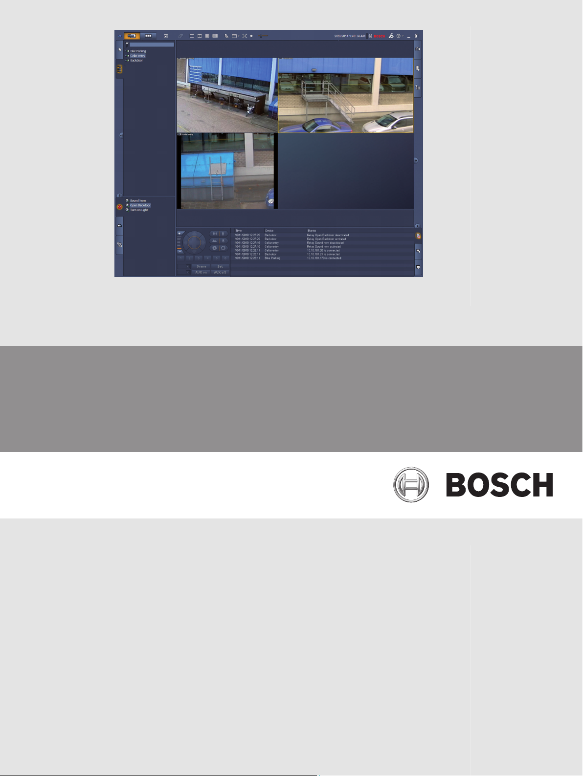
3.3
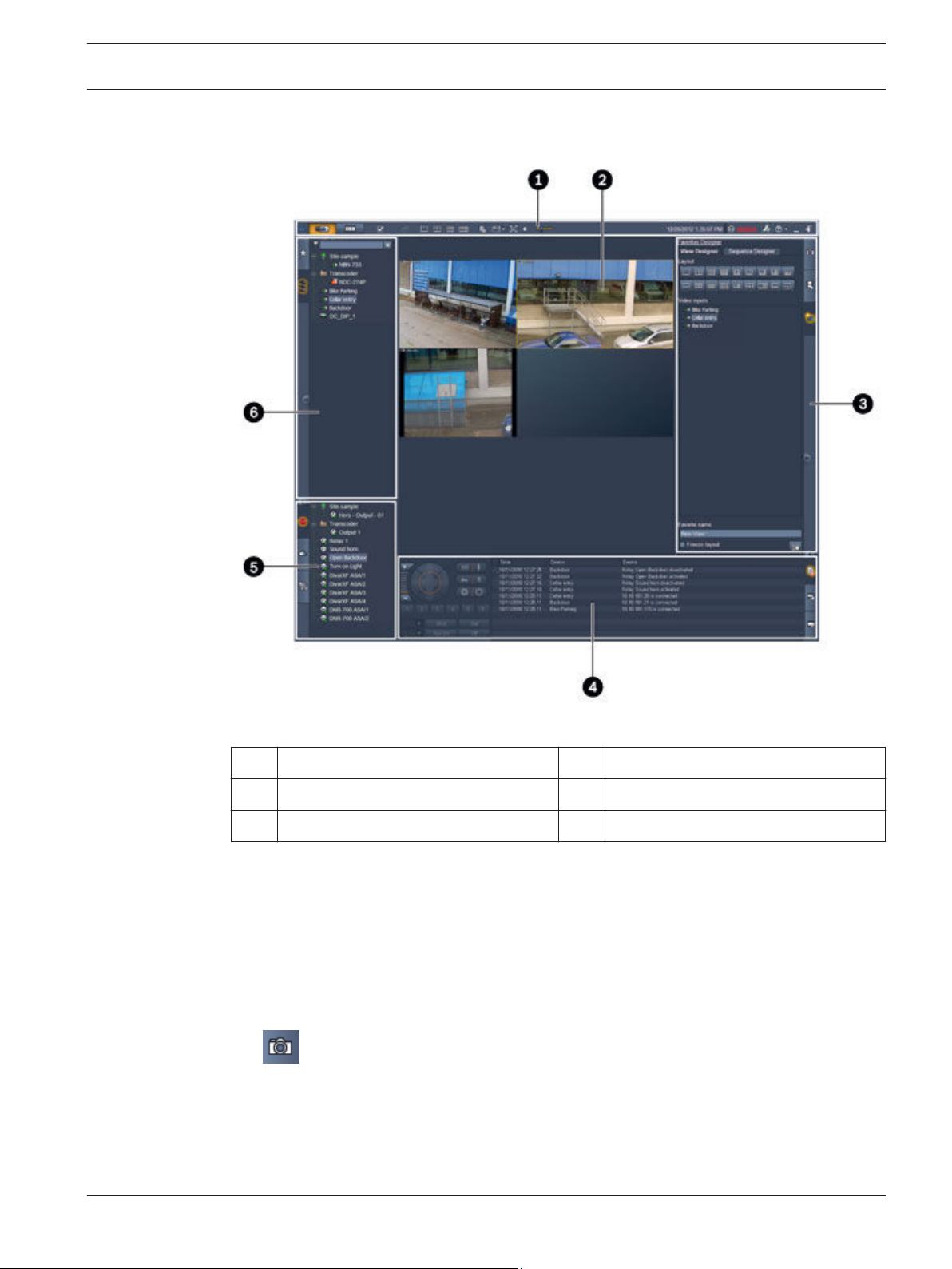
Basic overview
Figure 3.1: User interface layout (sample screenshot of an application in live mode)
Toolbar 4 Information and operation pane
1
2 Cameo area 5 Accessories and archive pane
3 Task pane 6 System pane
Toolbar
Contains icons for various functions (see below for details).
Cameo area
Displays the single viewlets called cameos that are used to show the video. There can be one
or many cameos in this area. The area can be dragged to a second monitor, if installed.
Task pane
Click the tabs to open the panels for the respective mode.
– In both modes:
Cameo capture panel
Bosch Sicherheitssysteme GmbH Software manual 2014.09 | v1.6 | DOC
Page 16
en | User interface Video Client
16
– In live mode:
Instant playback panel
Favorites designer panel
If a monitor wall is configured, an additional tab is displayed:
Monitor wall panel
– In playback mode:
Event search panel
VCA search panel
If a Divar 700-connected camera is allocated to the system, an additional tab is displayed:
Text search panel
Information and operation pane
Click
in the bottom right of the window to open the pane. In the left part, it offers a
console to control cameras or playback. In the right part, click the tabs to open the panels for
the respective mode.
– In live mode:
Logbook panel
– In playback mode:
Timeline panel
– In both modes:
Export jobs panel
Cameo calibration panel
Accessories and archive pane
Click
in the bottom left of the window to open the pane. Click the tabs to open the
panels for the respective mode.
– In live mode:
Alarm outputs panel
Alarm inputs panel
– In playback mode:
Exports panel
– In both modes:
Screenshots panel
2014.09 | v1.6 | DOC Software manual Bosch Sicherheitssysteme GmbH
Page 17
Video Client User interface | en 17
System pane
Click the tabs to open the panels.
– Favorite views panel
– Video device list panel
For a list of the icons shown in these panels see below.
3.4
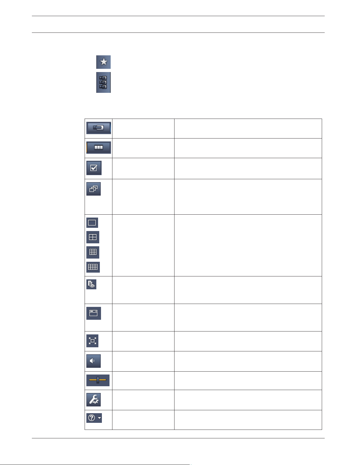
Toolbar icons
Live mode Switches the Video Client application to live mode
Playback mode Switches the Video Client application to playback mode
User preferences Displays a dialog box for setting user preferences.
Start/stop sequencing
(only in live mode)
Quick views Some layouts are offered to quickly arrange the cameo
(orange highlighting).
(blue highlighting).
Starts and stops a sequence of cameo views (only active
if you have selected a sequence or multiple views in the
Favorite views panel or multiple cameras in the Video
device list panel).
area. The icon on the button represents the layout. The
number of buttons differs between live and playback
mode.
Open text viewer
pane
Select cameo
decoration
Maximize cameo area Maximizes the cameo area to the size of the Video Client
Audio on/off Switches audio off and on.
Change volume Adjusts the audio volume.
Start Configuration
Manager
Show help index Opens the help index offering a list of available help
Bosch Sicherheitssysteme GmbH Software manual 2014.09 | v1.6 | DOC
Opens the Text viewer pane (in live mode only available
if a Divar 700-connected camera is allocated to the
system).
Selects how the cameos are displayed: add additional
information in a top bar or as overlay. Furthermore, you
can overlay the cameo with a time stamp and VCA data.
window. Press Esc to switch back to normal mode.
Opens the Configuration Manager application in a
separate window.
files.
Page 18
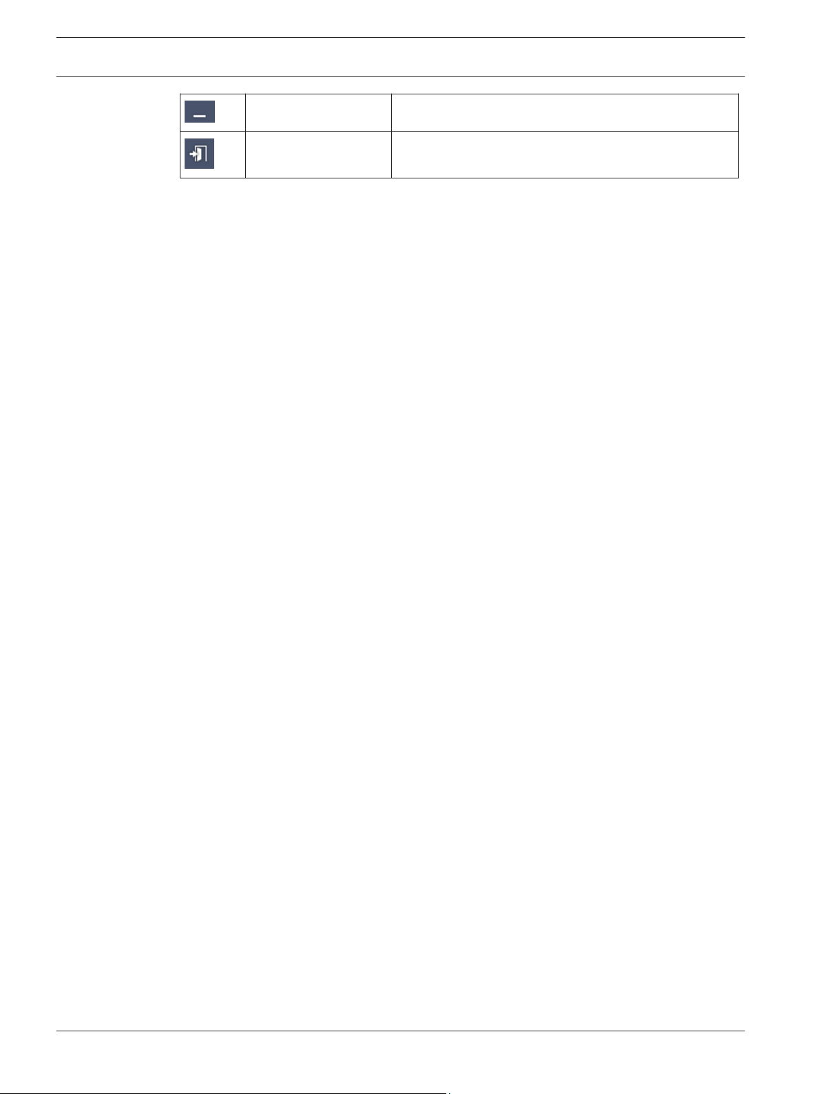
18 en | User interface Video Client
Minimize Minimizes the Video Client window to the task bar.
Log off Logs off the current user and returns to the logon
window.
The date and time, and the CPU usage bar are also displayed on the toolbar. Hover over the
CPU usage bar to see the CPU usage as a percentage.
Double-click the toolbar to maximize the application window to fill the screen. Double-click it
again to return to normal mode.
2014.09 | v1.6 | DOC Software manual Bosch Sicherheitssysteme GmbH
Page 19

Video Client Setting user preferences | en 19
4
Setting user preferences
These settings are saved for the user who is logged on and are applied each time this user
logs on with the same computer.
1. In the toolbar, click to open the User preferences dialog box.
2. Click the desired tab and configure the settings as described below.
3. Click OK to save changes and close, or Cancel to close the dialog box without change.
Settings tab
1. Select the Bring to foreground on alarm check box if you want the application window to
maximize in case of alarm.
2. Select the check box for the alarms and errors items to be activated.
The computer beeps on the specified alarms or errors.
3. By default, the time of the Video Client application is displayed for the optional time
stamp in the cameos. Select the Show local device time check box if you prefer the
actual time set on the device to be displayed.
4. Select the Kiosk mode check box to expand the Video Client window permanently to full
screen. When in kiosk mode a user cannot resize the Video Client window or exit the
application.
The check box is only available to the administrator. This feature requires a restart for it
to take effect.
5. Select a sequence dwell time from the list to determine how long a sequenced view
remains displayed.
6. Select a time offset from the list for instant playback.
7. If you have multiple monitors set up in Windows, select the Enable second monitor check
box to use one of these monitors as a second monitor. Select the monitor you wish to use
in the box below.
Directories tab
1. Enter the locations that will be monitored for exported video. All files in these locations
will be listed in the Exports panel in the accessories and archive pane (only available in
playback mode).
2. Enter the locations that will be monitored for captured images. All files in these locations
will be listed in the Screenshots panel in the accessories and archive pane.
The location for workstation recordings is displayed for information. It is set in the
Configuration Manager application. Add the path to the list of monitored export locations if
you want to access such recordings in playback mode.
Monitor wall tab
You can only set up a monitor wall if you have added decoders to your system. The available
decoders are listed in the Decoders box. Decoders that belong to a site are only listed if the
site is connected.
Note that this tab is not available if you have used direct logon.
1. Drag a decoder from the Decoders box to a free position on the monitor wall grid.
Alternatively, select a decoder and a free position and click
2. Drag a decoder in the grid to a new position to rearrange the grid.
Bosch Sicherheitssysteme GmbH Software manual 2014.09 | v1.6 | DOC
.
Page 20

20 en | Setting user preferences Video Client
3. To free a position, select it and click . The decoder is removed from the grid and
listed in the Decoders box.
See also
– Video Client setup, page 10
2014.09 | v1.6 | DOC Software manual Bosch Sicherheitssysteme GmbH
Page 21

Video Client Working with cameos | en 21
5
5.1
Working with cameos
Cameos are single viewlets used to show live video, recordings, exported video clips and
archived screenshots. They are displayed in the cameo area.
Making quick views
A quick view is the fastest way to display video. Decide for a cameo layout and populate the
cameos with the desired video.
In live mode, the settings for each quick view are saved for the user who is logged on. They are
applied each time this user logs on with the same computer. Thus, if you log on again any
quick view shows its most recent video-to-cameo assignments.
In playback mode, assignments are only valid during the running session.
To decide for a cameo layout:
Frequently used cameo layouts are provided as quick view buttons. The icon on the button
represents the layout. The number of available buttons is different for live and playback mode.
4 In the toolbar, click a quick view button to change the layout of the cameo area:
– Single cameo
– 2×2 cameos
–
3×3 cameos (only in live mode)
–
Once you have populated the cameos, clicking a button displays the corresponding quick view
with the most recent video-to-cameo assignments.
Populating cameos
In live mode, you can view video from any active camera listed in the system pane.
In playback mode, video recordings created by cameras that have on-board storage (a memory
card), or direct iSCSI or VRM storage, or DIVAR storage can be viewed. Devices with such
tracks or VRM backups show next to the device icon.
The cameras of a site are only available in the list if the site is connected. Note that you can
only have cameras from one site in a view since you can only connect to one site at a time.
If you have assigned cameras of a different site to another quick view the site will
automatically be connected if you change to that view.
Ways to populate a single cameo:
– In live mode:
– In playback mode:
4×3 cameos (only in live mode)
– Select the cameo and double-click the desired camera in the system pane.
– Drag a camera from the system pane to a cameo.
– Right-click the cameo and select a video input from the list.
Locate the devices that show
device node to see if the device offers more than one track or backup.
– Select the cameo and double-click the desired track or backup.
– Drag the desired track or backup to a cameo.
next to the device node in the system pane. Expand the
Bosch Sicherheitssysteme GmbH Software manual 2014.09 | v1.6 | DOC
Page 22

22 en | Working with cameos Video Client
– Right-click the cameo and select the desired track or backup from the list of video
inputs.
The video is displayed in the cameo. The aspect ratio of the cameo adapts to the aspect ratio
of the video.
Ways to populate multiple cameos:
– In live mode:
– Select multiple cameras and drag them from the system pane to a cameo.
– In playback mode:
5.2
Locate the devices that show
device node to see if the device offers more than one track or backup.
– Drag a device with multiple tracks or backups to a cameo.
– Mark multiple devices with tracks or backups and drag them to a cameo.
– Mark multiple tracks or backups from different devices and drag them to a cameo.
The cameo to which you have dragged your selection has a colored border to mark it as
selected. It shows the video of the topmost entry of your selection. The other cameos are
filled from left to right and top to bottom. The aspect ratio of the cameo column adapts to the
aspect ratio of the camera.
To reorder the cameo positions:
1. In the toolbar, click
2. To reorder cameos, drag the title bar of a cameo to the new position.
To clear a cameo:
– Click the delete icon in the header of the selected cameo.
– Alternatively, right-click a cameo and select Stop display.
and select Title bar.
next to the device node in the system pane. Expand the
Calibrating the cameo
The Cameo calibration panel shows the settings for brightness, sharpness, contrast, and the
gamma correction value for the various color channels of the selected cameo. Adapt the values
to your needs.
1. In the information and operation panel, click
2. To see the values for a specific color channel, click the rectangle of the respective color.
To calibrate the cameo:
1. Click the tricolored rectangle if you want to change the settings for all color channels
simultaneously. Otherwise, click the rectangle of the respective color.
As soon as you change one of the values, the
indicate that the image calibration settings for the cameo differ from the original settings
for the camera image.
2. Click
the cameo.
3. Click to decrease the contrast, or click to increase the contrast for the
cameo.
2014.09 | v1.6 | DOC Software manual Bosch Sicherheitssysteme GmbH
to decrease the brightness, or click to increase the brightness for
to open the Cameo calibration panel.
icon is displayed in the cameo to
Page 23

Video Client Working with cameos | en 23
4. Click to decrease the gamma correction value, or click to increase the
gamma correction value for the cameo.
5. Click to decrease the sharpness, or click to increase the sharpness for
the cameo.
6. Click Set as default to save the settings for the cameo.
7. Click Reset to reset the values to the original settings for the camera image.
5.3
Configuring cameo decorations
In the video, overlays generated by the device itself are displayed, like camera names, alarm
messages, times and dates. Such overlays are configured in the Configuration Manager
application. Furthermore, video image overlays provide important status information.
Nevertheless, you can also configure the cameo to show specific information.
1. In the toolbar, click
2. If you want to display the camera name along with the device icon in the cameo, select
the desired decoration type:
– Title overlay
Displays the information as an overlay.
– Title bar
Adds a title bar with the information to the cameo. In multi-cameo layouts, drag and
drop the title bar to rearrange the cameos.
3. Select No decoration if you don’t want the camera name to be displayed.
4. Select Display time to add a time stamp overlay.
By default, the time of the Video Client application is displayed as shown in the toolbar.
In the User preferences dialog box, you can define to show the local time of the device,
instead.
5. Select Display VCA data to have information from the video content analysis shown as an
overlay, if available.
to open the menu.
See also
– Setting user preferences, page 19
– Video image overlays, page 58
5.4
Bosch Sicherheitssysteme GmbH Software manual 2014.09 | v1.6 | DOC
Cameo context menu
Right-click a cameo to display the context menu. Not all commands are always available:
– Select video input
– In live mode: lists available cameras
– In playback mode: lists cameras with tracks or backups available
– Start digital zoom/Stop digital zoom
Starts and stops the digital zoom
– Start workstation recording/Stop workstation recording (only in live mode)
Starts and stops workstation recording
– Maximize cameo/Restore cameo size
Switches active cameo to single-cameo view and back
– Stop display
Clears the cameo
Page 24

en | Working with cameos Video Client
24
– Show
Lists the streams offered by the device; allows to select another stream for display than
the preferred one that is set for the camera in the system pane (only valid until you
change the stream or video input selection)
– Capture screenshot
Opens the Cameo capture panel with a screenshot of the active cameo
– Open instant playback (only in live mode)
Opens the Instant playback panel to display instant playback, if available
– Properties
– In live mode: opens a dialog box with the properties of the video input
– In playback mode: opens a dialog box with the properties of the track or backup
– Intelligent tracking (only in live mode)
Allows to switch on intelligent tracking if supported by the device
In live mode, Send to monitor and Send view to monitor commands are also available if a
monitor wall is configured.
See also
– Digital zoom, page 38
– Workstation recording, page 44
– Saving and viewing screenshots, page 43
– Instant playback, page 39
– Setting user preferences, page 19
– Populating a monitor wall, page 40
2014.09 | v1.6 | DOC Software manual Bosch Sicherheitssysteme GmbH
Page 25

Video Client Working with the system pane | en 25
6
6.1
Working with the system pane
Two side tabs are located on the top left of the Video Client window:
– Click to open the Favorite views panel.
It is empty until you have set up your own favorite views (see below for details).
– Click to open the Video device list panel.
It shows all available cameras in your system:
– With direct logon: all cameras belonging to the URL or IP address entered
– With regular logon: all cameras of your system as configured with the Configuration
Manager application
See also
– How to log on, page 8
– Configuring with Configuration Manager, page 8
System pane icons
Each entry in the panels of the system pane has an icon related to its type. Overlays and color
marks give additional information on the status. Various combinations of icons and overlays
are possible. Below you find lists with examples for the icons in the system pane.
Device icons
Device icons are used both in the Favorite views panel and in the Video device list panel.
Body camera not connected (grey dot)
Body camera connected (green dot)
Dome camera connected (green dot)
Body camera with video loss (red cross)
Body camera is in alarm mode (warning triangle)
Body camera with motion detected (walker)
Body camera with motion alarm (walker with warning triangle)
Body camera allocated via transcoder and connected (gem and green dot)
Body camera allocated via transcoder and in alarm mode (gem and warning triangle)
The gem indicating a device allocated via transcoder may also change color:
– white: a transcoded stream is available
– green: a transcoded stream is shown
– red: no transcoded stream is available
Note:
If configured accordingly, DIVAR-connected cameras show the alarm mode overlay to
indicate that the connection is interrupted:
– Analog cameras are physically disconnected.
– IP cameras are offline.
Bosch Sicherheitssysteme GmbH Software manual 2014.09 | v1.6 | DOC
Page 26

26 en | Working with the system pane Video Client
Video device list icons
With regular logon, additional icons are available in the Video device list panel, depending on
how you set up the system with the Configuration Manager application:
– Group devices for better overview in the list
– Convert a group into a site to limit the number of simultaneous connections
By default, when you start Video Client all cameras in the system that are not belonging
to a site are connected automatically. The connection to a site and its devices is
established in an extra step. It is only possible to connect to one site at a time.
Site not connected (grey dot)
Site connected but with some devices that are not accessible (yellow dot)
Site connected with all allocated devices accessible (green dot)
Group
The group icon is also used to group cameras connected to a transcoder that is added to your
system.
Favorite views icons
The icons for the different views reflect the chosen cameo layout. Only some of the variants
are listed here as examples.
6.2
View with 3×3 cameos
View with 4×3 cameos
View with 1+12 cameos (centered) that includes a device of a connected site (green
dot)
View with 2×2 cameos that includes a device of a site that is currently not connected
(grey dot)
Sequences folder under which all defined sequences are listed; this folder automatically
is added once you have defined a sequence
Sequence
The sequence icon not only marks the sequence itself, but is also used as an overlay to mark
the currently active view or device of a running sequence:
View with 2×2 cameos currently shown in the running sequence
Body camera currently shown in the running sequence; note that other overlays (for
example the red cross for video loss) are not visible while the sequence overlay is displayed
Video device list panel
The Video device list panel shows all configured devices.
Working with the Video device list panel
– To filter the list, type a search string into the input box on top of the panel.
The video device list is filtered on-the-fly hiding all entries that do not match the string.
The filter is not case-sensitive and ignores white spaces.
2014.09 | v1.6 | DOC Software manual Bosch Sicherheitssysteme GmbH
Page 27

Video Client Working with the system pane | en 27
– If a group or site name matches, all devices allocated to it are listed.
– If an allocated device matches, it is listed together with the corresponding group or
site but the non-matching devices of that group or site are hidden.
– Click to expand a group or connected site and see the cameras assigned to it. Click
to collapse the group or site.
– Double-click a site to connect to it. Note that you can only connect to one site at a time.
– Right-click an entry to open a context menu.
Device context menu
Right-click a device to display the context menu. Not all commands are always available:
– Connect
Establishes a connection
– Disconnect
Terminates the connection
– Sequence
Starts a sequence with the selected devices (at least 2 devices must be selected)
– Send to monitor
Lists the available monitors for selection (main, second, or wall if set up)
– Preferred stream
Lists the streams as provided by the device; select the default stream for display in a
cameo
– Properties
Opens the corresponding dialog box
Site context menu
Right-click a site to display the context menu. Not all commands are always available:
– Connect
Establishes a low-bandwidth connection to the site; by default, this is the connection
type if you double-click the site icon
– Disconnect
Terminates the connection
6.3
Bosch Sicherheitssysteme GmbH Software manual 2014.09 | v1.6 | DOC
Favorite views panel
In live mode, the Favorite views panel shows the various views and sequences that have been
made in the Favorites designer panel. In playback mode, the sequences are not shown.
Note:
If the application was started from the command line with the “-sites” parameter, then the
Favorite views tab is replaced by the Site connector tab.
Working with the Favorite views panel
– In live mode, double-click a view to see it in the cameo area. If the view includes a camera
belonging to a site, the site is automatically connected.
– In playback mode, you cannot show a view in the cameo area. But you can expand the
entries to locate devices with recordings (
– Click to expand an entry:
– For a view, you see the cameras assigned to it
– For the sequence folder, you see the sequences that are available
next to the device icon).
Page 28

en | Working with the system pane Video Client
28
– For a sequence, you see the views and cameras belonging to the sequence
– Click to collapse the entry.
– Right-click an entry to open a context menu.
Device context menu
Right-click a device to display the context menu. Not all commands are always available:
– Connect
Establishes a connection
– Disconnect
Terminates the connection
– Sequence
Starts a sequence with the selected devices (at least 2 devices must be selected)
– Send to monitor
Lists the available monitors for selection (main, second, or wall if set up)
– Preferred stream
Lists the streams as provided by the device; select the default stream for display in a
cameo
– Properties
Opens the corresponding dialog box
View context menu
Right-click a view to display the context menu. Not all commands are always available:
– Sequence
Starts a sequence with the selected views (at least 2 views must be selected)
– Send to monitor
Lists the available monitors for selection (main, second, or wall if set up)
– Save view
Saves any changes to the view like a new video-to-cameo assignment or a rearrangement
of cameos
– Delete view
Deletes the view from the list without further notice; if the view was displayed in the
cameo area it remains there until you select a different view
– Rename view
Allows to type a new name for the view
– Properties
Opens the corresponding dialog box
Sequence context menu
Right-click a sequence to display the context menu. Not all commands are always available:
– Sequence
Starts a sequence with the selected sequences (at least 2 sequences must be selected)
– Send to monitor
Lists the available monitors for selection (main, second, or wall if set up)
– Delete sequence
Deletes the sequence from the list without further notice; if the sequence was running in
the cameo area it remains there until you select a different sequence
– Rename sequence
Allows to type a new name for the sequence
2014.09 | v1.6 | DOC Software manual Bosch Sicherheitssysteme GmbH
Page 29

Video Client Working with the system pane | en 29
– Properties
Opens the corresponding dialog box
See also
– Command line start, page 57
6.4
6.4.1
Setting up favorites
It is recommended that you take the time to set up a collection of favorite views and
sequences. A view is a collection of video-to-cameo assignments that can be recalled for
instant live viewing. Such views can be included into favorite sequences together with single
cameras. You can set up favorites only in live mode.
4 In the task panel, click
On the Favorites designer panel you find two tabs:
– Click the View designer tab to set up and save favorite views.
– Click the Sequence designer tab to define and save favorite sequences.
Making a favorite view
Use the View designer tab to make your favorite views. Camera views can be grouped in a
logical way; for example, all cameras showing an entrance to a building.
1. Click a layout button in the View designer tab to select it. The layout appears in the
cameo area.
If you continue to click a button for an asymmetrical layout, the layout orientation
changes.
2. Drag cameras from the Video inputs list to the cameos.
The cameras of a site are only available in the list if the site is connected. Note that you
can only have cameras from one site in a view since you can only connect to one site at a
time.
3. In the Favorite name box, enter a name for the new view.
4. Select the Static layout check box so the aspect ratio of the cameos does not change on
re-assignment.
to open the Favorites designer panel
5. Click .
The view is stored in the Favorite views panel.
You can drag alarm outputs and alarm inputs to a view in the Favorite views panel to create
system overviews.
6.4.2
Bosch Sicherheitssysteme GmbH Software manual 2014.09 | v1.6 | DOC
Making a favorite sequence
Use the Sequence designer tab to make your favorite sequences. Select favorite views and
single cameras and put them into the desired order.
The sequence dwell time is set in the User preferences dialog box.
To set up a favorite sequence:
1. In the Views box, select a view or a device.
The cameras of a site are only available in the list if the site is connected. You can have
cameras of different sites in one sequence. The respective site will be connected
automatically while the corresponding camera view is displayed in the sequence.
Page 30

en | Working with the system pane Video Client
30
2. Click to add the selection to the Sequence list box. Continue doing this until your
list is complete.
3. To remove an entry from the sequence list, select it and click
.
4. To rearrange the entries in the sequence list, select one or more entries and click the
move up or move down buttons.
5. In the Sequence name box, enter a name for the new sequence.
6. Click
.
The sequence is stored in the Favorite views panel in the Sequences folder.
To modify a favorite sequence:
You can easily modify sequences or use them as starting point for a new sequence.
1. To load the list of an existing sequence, click
in the Sequence designer tab.
The Select sequence dialog box appears.
2. Select the desired sequence.
3. Click OK.
The components of the selected sequence are listed in the Sequence list box and can be
rearranged as desired.
See also
– Setting user preferences, page 19
2014.09 | v1.6 | DOC Software manual Bosch Sicherheitssysteme GmbH
Page 31

Video Client Viewing live and recorded video | en 31
7
Viewing live and recorded video
Both in live and playback mode, the video is displayed in the cameo area. Depending on the
configuration of the cameos and of the device configuration, additional information is
displayed. Furthermore, video image overlays provide status information (see below for
details).
To view live video:
1. Set up a collection of quick views and favorite views to suit your needs.
2. Start the display of the desired view:
– In the Favorite views panel, double-click a pre-defined view.
Alternatively, drag the view to the cameo area.
– In the toolbar, click one of the quick view buttons to display the corresponding quick
view with its most recent video-to-cameo assignments.
3. To quickly change a video-to-cameo assignment, drag another camera from the system
pane to the cameo:
– For a quick view, the new assignment is retained until you assign another camera.
– A favorite view turns back to the original assignment whenever you call it up unless
you right-click the view and select Save view from the context menu.
To view recorded video:
In playback mode, no favorite views can be called up. Quick views retain the video-to-cameo
assignment only for the time of the running session.
1. In the toolbar, click a quick view button to select the desired cameo area layout.
2. Populate the cameos with tracks or backups as described above.
3. To quickly change a video-to-cameo assignment, drag another track or backup from the
system pane to the cameo.
The assignment is retained until you assign another track or backup.
Viewing transcoded streams
If you are displaying a transcoded stream in a cameo, placing the pointer over the cameo
provides you with additional options:
– Use the slider to decide for higher frame rate
better the image quality the lower the frame rate and vice versa. Refer to the image in the
cameo to decide which setting suits your needs.
– Click to refresh the display.
See also
– Video image overlays, page 58
– Making quick views, page 21
– Setting up favorites, page 29
7.1
Bosch Sicherheitssysteme GmbH Software manual 2014.09 | v1.6 | DOC
Starting sequences
In live mode, Video Client allows for automatic switching between different views or cameras.
The quickest way to start a sequence is using the corresponding button in the toolbar as
described below. Such sequences are not stored and have to be set up again any time you
want to use them.
or for better image quality . The
Page 32

32 en | Viewing live and recorded video Video Client
Another possibility is to set up favorite sequences in the Sequence designer panel. These
sequences are saved in the Favorite views panel.
Whenever a sequence switches to the next display, the corresponding name of the camera or
view is shown briefly in the top of the cameo area for information.
The sequence dwell time is set in the User preferences dialog box.
To start a sequence:
7.2
In the toolbar, the sequence icon
– In the Video device list panel, select multiple cameras and click the sequence icon to
start sequencing the selected cameras.
– In the Favorite views panel, select a multi-cameo view and click the sequence icon to
start sequencing the cameras within that view in a single-cameo display.
– In the Favorite views panel, select multiple views and click the sequence icon to start
sequencing between the views and not within the views.
– In the Favorite views panel, select a sequence and click the sequence icon to start.
Alternatively, double-click the entry to start the sequence.
Click the icon again to stop automatic switching.
See also
– Making a favorite sequence, page 29
– Setting user preferences, page 19
is available once you have selected multiple entries.
Going into detail
With Video Client, viewing details in the video is not limited to using the camera zoom. Enlarge
single cameos or the entire cameo area or use the digital zoom.
To enlarge a single cameo:
– In multi-cameo layout, double-click a populated cameo to switch to single-cameo layout
and back again.
– Alternatively, click
area. Click to turn back to multi-cameo layout.
Note that if you have not activated the title bar, the icons are only visible if the pointer is
in the cameo.
To enlarge the cameo area:
– Close any pane that you do not need. The cameo area fills the available space enlarging
the single cameos.
– In the toolbar, click
window. Click the button again on the auto-hide toolbar or press Esc to switch back to
normal mode.
To enlarge the application window to fill the full screen:
– Press F11 to maximize the application window to fill the full screen. Press the key again
to switch back (for a list of shortcut keys see below).
– As administrator, select the Kiosk mode check box in the User preferences dialog box to
permanently set the application window to full-screen view.
2014.09 | v1.6 | DOC Software manual Bosch Sicherheitssysteme GmbH
in the header of the selected cameo to enlarge it to fill the cameo
to maximize the cameo area to the size of the application
Page 33

Video Client Viewing live and recorded video | en 33
See also
– Digital zoom, page 38
– Standard keyboard shortcut keys, page 52
– Setting user preferences, page 19
7.3
7.3.1
Controlling cameras
You can control controllable cameras by using the mouse on the corresponding cameo or by
using the controls on the information and operation pane.
Camera controls
Use the camera controls to control the camera in the selected cameo. Make sure to have the
correct cameo selected before starting (indicated by the orange frame).
For more information on the digital zoom, see below.
Figure 7.1: Camera controls
1
Pan left button 9 Set button
2 Tilt down button 10 AUX off button
3 Tilt up button 11 AUX on button
4 Pan right button 12 Box for AUX command number
5 Zoom out/ in buttons 13 Box for scene number
6 Far/near focus buttons 14 Scene selection buttons
7 Close/open iris buttons 15 Digital zoom buttons
8 Scene button
To pan and tilt:
– Click and hold the up and down arrows for tilt.
– Click and hold the left and right arrows to pan.
– Release the mouse button to stop camera movement controls.
To control zoom, focus, and iris:
– Click and hold
–
Click and hold to focus on far objects; click and hold to focus on near
objects.
to zoom out; click and hold to zoom in.
Bosch Sicherheitssysteme GmbH Software manual 2014.09 | v1.6 | DOC
Page 34

34 en | Viewing live and recorded video Video Client
– Click and hold to close the iris; click and hold to open the iris.
– Release the button to stop camera adjustment controls.
To move the active camera to a scene:
A scene is a stored camera position with defined pan, tilt and zoom settings. The available
number of such scenes depends on the camera type.
1. Enter a scene number in the box next to the Scene button.
2. Click Scene (or press ENTER) to move the active camera to the selected scene.
Alternatively, click buttons 1 to 6 for immediate positioning to one of the first 6 scenes.
To store the current position of the camera as a scene:
1. Position the camera as desired.
2. Enter a scene number.
3. Click Set to store the active scene under the selected number.
To control AUX functions:
AUX functions are special commands for controlling cameras that support such commands.
1. In the box next to the AUX on button, enter the number of the desired AUX command.
2. To switch on the AUX command, click AUX on (or press ENTER).
3. To switch off the AUX command, click AUX off.
7.3.2
See also
– Digital zoom, page 38
Mouse control
If you have a controllable camera in use, in-window controls are provided in the cameo to
control the camera with the mouse.
1. Click the cameo of the camera to make it active.
2. Place the pointer on the active cameo. It changes to a direction arrow.
3. With the direction arrow pointing to the desired direction, click and hold the left mouse
button.
The camera moves in the direction indicated.
4. Pan and tilt speed depends on the position of the pointer on the cameo. Click closer to
the edge of the cameo to increase the speed; click closer to the center to decrease the
speed.
5. Release the button when the camera is positioned.
6. Rotate the mouse wheel to zoom in or out.
Panoramic cameras
The video image of panoramic cameras exceeds the cameo. Therefore, in-window controls are
provided in the cameo to allow you to move to another section of the image similar to the
digital zoom (see below for details).
See also
– Digital zoom, page 38
7.4
2014.09 | v1.6 | DOC Software manual Bosch Sicherheitssysteme GmbH
Controlling playback
In the information and operation pane, use the playback controls and the Timeline panel to
control playback of recorded video. Controlling is valid for all populated cameos.
Page 35

Video Client Viewing live and recorded video | en 35
7.4.1
Playback controls
With the playback controls on the information and operation pane you mainly control playback
speed and direction or move to points of interest within the recordings.
For more information on the digital zoom, see below.
Figure 7.2: Playback controls
1
Decrease playback speed and play
reverse button
2 Export button 9 Go to previous/next event buttons
3 Jog dial 10 Arrow buttons to increase/decrease
8 Go to earliest/latest recording buttons
the selected value in the date/time box
4 Pause button 11 Date/time box
5 Play button 12 Playback speed slider
6 Increase playback speed and play
13 Digital zoom buttons
forward button
7 Move one frame back/forward buttons
To control the playback:
1. Click
to start playback for all cameos.
The handle of the speed slider is set to 1 (real-time playback).
2. Playback speed and direction can be selected in different ways:
– Drag the jog dial to the left or right to play back in reverse or forward. The more you
drag the jog dial the higher the playback speed. Releasing the jog dial pauses the
playback.
– Click
to increase the playback speed or click to decrease it. With each click
the handle of the speed slider is moved further once.
– Drag the handle of the speed slider to the desired value:
1 = real-time playback
0 = pause
> 1 to 64 = increasing fast-forward
< 1 to 0 = slow-motion forward
0 to -64 = increasing reverse motion
3. Click
Bosch Sicherheitssysteme GmbH Software manual 2014.09 | v1.6 | DOC
to pause playback.
Page 36

36 en | Viewing live and recorded video Video Client
To move to points of interest:
– Click to move back one image; click to move forward one image. Hold the
button to display the next image every 0.5 seconds.
The buttons are only available when playback is paused.
– Click
recording.
– Click to move to the previous search event; click to move to the next
search event.
The buttons are only available if a search was performed successfully. The events are
marked by little icons in the recording indicator bar.
Date and time box
In the box, the date and time of the hairline position are shown.
1. Click one of the values to activate it, for example the day or the seconds.
The background color for the activated value changes.
2. Click the up or down button
Alternatively, type the desired value.
– If a recording is available for the entered value for one of the cameos, the hairline
jumps to this time. The corresponding image is displayed in the cameo.
– If no recording is available for the entered value, nothing happens.
See also
– Digital zoom, page 38
– Searching through recordings, page 47
to move to the earliest recording; click to move to the latest
to count up or down the activated value by one.
7.4.2
2014.09 | v1.6 | DOC Software manual Bosch Sicherheitssysteme GmbH
Timeline panel
The Timeline panel offers additional information on the recordings in the cameo area and a
context menu. It helps to quickly navigate through recordings.
4 In the information and operation pane in playback mode, click to open the Timeline
panel.
A timeline scale is shown with a recording indicator bar for each of the populated
cameos. All cameos are synchronized to the same playback time.
The recording indicator bar marks a recording in light grey. Additional colors are used to mark
special events. Place the pointer on a colored segment for further information.
Color codes in the recording indicator bar:
Recording without further events (grey)
Motion event (yellow)
Page 37

Video Client
Viewing live and recorded video | en 37
Alarm input has changed its state (red)
VRM-protected recording (hatched grey)
Video loss (black)
Text alarm (orange)
Some events from Divar 700-connected cameras only color the bottom half of the indicator
bar:
Motion event (grey/yellow)
Alarm input has changed its state (grey/red)
Text trigger (grey/orange)
Search results for event and VCA searches are marked in the recording indicator bar by little
icons:
To change the timeline scale:
– Click the
or buttons to adjust the timeline scale.
Alternatively, place the pointer on the timeline scale and rotate the mouse wheel.
The selected interval value is displayed between the two buttons, for example 3 minutes
or 1 week. The shorter the indicated interval the more you zoom in on the timeline.
– To show the full timeline for an entire recording, click until All is displayed between the
buttons.
To navigate in the timeline:
– To move back and forward in time, use the arrow buttons above the timeline scale or drag
the timeline scale.
– Click anywhere below the timeline scale.
– If a recording is available for that point in time, the hairline jumps there.
– If no recording is available the hairline jumps to the beginning of the next available
recording.
– The corresponding images are displayed in the cameo area. Use the playback control
console for the required playing option.
To select a time period:
You can select a time period and use this selection for further tasks such as exporting video
data.
– Drag the bottom arrow handles of the hairline to select a time period.
– Drag the left or right edge of the selection to change the size of the selection.
Bosch Sicherheitssysteme GmbH Software manual 2014.09 | v1.6 | DOC
Page 38

38 en | Viewing live and recorded video Video Client
– Drag the bottom of this selection to move the selection.
– Alternatively, drag the pointer over any section below the timeline scale that includes a
recording.
– Right-click the selection to open context menu for further tasks.
Timeline context menu
The commands available in the context menu depend on where you have clicked in the
Timeline panel. Some commands for example are only available if you right-click a selection.
When you click a context menu command that is not available for all cameos, the command is
executed only on the cameos that have this option available.
– Center at playback time
Moves the timeline scale to center the current playback time
– Center at selection
Moves the timeline scale to center the current selection (only available if you click outside
a selection)
– Authenticate
Checks the authenticity of the selected video
– Delete
Deletes the selected video (recorders only)
– Delete until
Deletes all recorded video for all cameos up to the end time of the selection (recorders
only)
– Export
Opens the Export dialog box for the selected video
– Backup
Makes a backup of the selected video (VRM only)
– Protect
Protects the selected video (VRM only)
– Unprotect
Unprotects the selected video (VRM only)
– Show event search results
Displays results of the event search (no other search results can be displayed at the same
time)
– Show text search results
Displays results of the text search (no other search results can be displayed at the same
time)
– Show VCA search results
Displays results of the IVA search (no other search results can be displayed at the same
time)
– Clear selection
Removes the selection
7.5
2014.09 | v1.6 | DOC Software manual Bosch Sicherheitssysteme GmbH
Digital zoom
The digital zoom allows you to magnify a section in the cameo for viewing. You can use it both
in live and playback mode, on video and screenshots. It does not affect the zoom of a
controllable camera.
Page 39

Video Client Viewing live and recorded video | en 39
1. With the pointer in a cameo, rotate the mouse wheel forward to zoom in.
Alternatively, right-click a cameo and select Start digital zoom from the context menu.
The pointer changes to a direction arrow and in the upper left of the cameo, a dark grey
box appears including a light grey box that represents the zoom area in relation to the full
picture.
7.6
7.7
2. Rotate the mouse wheel to zoom in and out, or click the
the controls on the information and operation pane.
3. Click the cameo to move to another section in the direction of the arrow.
Alternatively, drag the light grey box to the desired position.
4. If you zoom out completely, the digital zoom function switches off automatically.
and buttons of
Controlling audio
If audio is available, you can hear it for the selected cameo both in live and in playback mode if
you have enabled audio output.
– In the toolbar, click to enable audio output. The audio of the selected cameo is
heard, if available.
– Click
– Move the slider to the right to increase the volume.
to disable audio output.
Instant playback
In live mode, use instant playback to view the preceding seconds of recorded video for a
particular camera. The camera must, of course, have recording facilities.
The offset time for instant playback is set in the User preferences dialog box.
To view instant playback:
1. Right-click a cameo and select Open instant playback from the context menu.
The Instant playback panel opens.
2.
Click to start playback.
3. Click to pause playback.
4. Click to restart playback of the currently selected cameo with the offset time
defined in the User preferences dialog box.
A timeline scale is shown with a recording indicator bar below it.
Color codes in the recording indicator bar:
Recording without further events (grey)
Motion event (yellow)
Alarm input has changed its state (red)
Bosch Sicherheitssysteme GmbH Software manual 2014.09 | v1.6 | DOC
Page 40

40 en | Viewing live and recorded video Video Client
VRM-protected recording (hatched grey)
Video loss (black)
Text alarm (orange)
Some events from Divar 700-connected cameras only color the bottom half of the indicator
bar:
Motion event (grey/yellow)
Alarm input has changed its state (grey/red)
Text trigger (grey/orange)
To control instant playback:
7.8
1. When paused, click to move back one frame; click to move forward one
frame.
2. Drag the timeline scale to move it in time.
3. Right-click the indicator bar to center the timeline on the hairline that indicates the
playback position.
4. Drag the hairline to move playback to a point within a recording.
5. Enter the date and time in the time box to move the hairline to that point of the timeline.
See also
– Setting user preferences, page 19
Populating a monitor wall
With Video Client, you can configure live viewing on a monitor wall. Before you can populate a
monitor wall you have to set up the grid in the User preferences dialog box. Otherwise, the
Monitor wall panel is not available in the task panel.
1. In the task pane in live mode, click
In the upper section, the grid is shown as set up in the User preferences dialog box.
Positions that have a decoder assigned are marked with a darker grey border.
If you have assigned decoders belonging to different sites, only the decoders for the
currently connected site are available.
2. Move the pointer over a position. The border color changes to orange and the
corresponding decoder is displayed in the lower section of the panel.
3. Right-click a position in the upper section to select the layout via the context menu. In the
lower section, the decoder accordingly offers 1 or 4 cameos.
4. Drag a camera from the system panel to a decoder cameo in the lower section of the
Monitor wall panel.
Alternatively, use the context menu of the camera or cameo to assign it.
to open the Monitor wall panel.
2014.09 | v1.6 | DOC Software manual Bosch Sicherheitssysteme GmbH
Page 41

Video Client Viewing live and recorded video | en 41
5. Right-click a decoder cameo to open the context menu. Not all commands are always
available:
– Select video input
Lists available cameras
– Clear cameo
Cancels the current video-to-cameo assignment
– Stop sequencing
Stops running sequences
See also
– Setting user preferences, page 19
Bosch Sicherheitssysteme GmbH Software manual 2014.09 | v1.6 | DOC
Page 42

42 en | Controlling inputs and outputs Video Client
8
Controlling inputs and outputs
In the accessories and archive pane in live mode, the inputs and outputs of all devices in your
system are displayed according to the settings in the Configuration Manager application.
If the devices belong to a site, the inputs and outputs are only available while the site is
connected.
To control alarm outputs:
1. In the accessories and archive pane in live mode, click to open the Alarm outputs
panel.
2. If you want to show the alarm outputs of a disconnected site, right-click the site to
establish a connection via the context menu.
3. Double-click a connected alarm output to toggle its state.
4. Right-click an alarm output to toggle its state or view its properties via the context menu.
Connected alarm outputs like relays are indicated by a green overlay dot. The icon shows the
state of the alarm output:
A closed alarm output icon indicates an active output.
An open alarm output icon indicates an inactive output.
To control alarm inputs:
1. In the accessories and archive pane in live mode, click to open the Alarm inputs
panel.
2. If you want to show the alarm inputs of a disconnected site, right-click the site to
establish a connection via the context menu.
3. Right-click an alarm input to view its properties via the context menu.
Connected alarm inputs are indicated by a green overlay dot. The icon shows the state of the
input:
A red alarm input icon indicates an active input.
A grey alarm input icon indicates an inactive input.
2014.09 | v1.6 | DOC Software manual Bosch Sicherheitssysteme GmbH
Page 43

Video Client Saving and viewing screenshots | en 43
9
Saving and viewing screenshots
Capture still images from a camera and save them as screenshots to the computer’s hard disk.
The default locations for these screenshots are defined in the User preferences dialog box.
Saved screenshots are accessible via the Screenshots panel in the accessories and archive
pane if the location is listed in the User preferences dialog box.
To save a screenshot to the computer’s hard disk:
1. Click a cameo to select it.
2. In the task pane, click to open the Cameo capture panel.
The Cameo capture panel opens with the still image of the selected cameo displayed.
Identification information is shown under the image.
3. To update the image, click
4. To change the storage location, click the drop-down arrow. Either select a different
default location or click Browse... to enter a new path.
5. If you have entered a new path, select the check box to add the new location to the
monitored directories. Thus, you make sure that the file is displayed in the Screenshots
panel in the accessories and archive pane for easy access.
6. To change the file name, type the new name for the file.
7. To change the image format, click the drop-down arrow and select the desired format.
on the bottom left of the panel.
8. Click
The screenshot has the same resolution as the camera image.
9. Click to capture a new still image from the currently active cameo.
To display screenshots:
1. In the accessories and archive pane, click
2. The list of archived screenshots is displayed for all locations that you have defined in
User preferences > Directories > Monitored capture locations.
3. Right-click a file to view its properties via the context menu. Other menu options are:
– Rename screenshot
– Delete screenshot
4. To display a screenshot, double-click it or drag it to a cameo.
See also
– Setting user preferences, page 19
to save the image.
to open the Screenshots panel.
Allows to type in a new name for the file
Deletes the selected file without further warning
Bosch Sicherheitssysteme GmbH Software manual 2014.09 | v1.6 | DOC
Page 44

44 en | Exporting video clips Video Client
10
10.1
Exporting video clips
Export video clips from live video or from recordings to your computer’s hard. You can view
the stored files in playback mode or with the Export Player application.
See also
– Viewing stored clips, page 46
Workstation recording
In live mode, use workstation recording to manually export a video clip to your computer’s
hard disk. Such a workstation recording is limited to 10 minutes and only 2 workstation
recordings can be active at the same time. Date and time overlays are not saved.
The location for workstation recordings is set in the Configuration Manager application. It is
displayed for information in the User preferences dialog box. You can view the exported files
in playback mode if the path is added to the list of monitored locations in the User
preferences dialog box.
1. Place the pointer over a cameo.
2. Click the Start workstation recording icon
cameo.
Alternatively, right-click the cameo and select Start workstation recording from the
context menu.
The recording starts and the Export jobs panel is shown.
that appears in the bottom left of the
10.2
3. To stop workstation recording, either click
jobs panel.
See also
– Setting user preferences, page 19
in the cameo or click in the Export
Exporting video clips from recordings
In playback mode, export the video clips of a selected period for up to 4 recordings
simultaneously to your computer’s hard disk. The file size for exports is limited to 2 GB.
1. Click the Export button
box.
2. To change the default location, browse to the location in the computer’s file system
where the export file is to be stored.
3. If you have entered a new path, select the check box to add the new location to the
monitored directories. Thus you make sure that the folder is displayed in the Exports
panel in the accessories and archive pane for easy access.
4. To change the file name, type the new name for the file.
5. Enter new values in the From and To boxes to change the selection start and end date/
time.
Alternatively, click the calendar icons to pick a date.
6. By default, all cameras from the cameo area are listed for export. If you have assigned
different tracks from one camera, these are listed as separate entries. Clear the check
box to exclude an entry from export.
on the playback control console to open the Export dialog
2014.09 | v1.6 | DOC Software manual Bosch Sicherheitssysteme GmbH
Page 45

Video Client Exporting video clips | en 45
7. Select the Export format option to define the format of the exported file.
8. The estimated size of the export file is shown. Ensure that there is sufficient space to
store the export.
Note that the maximum file size for exports is 2 GB. Adjust your export settings if the
limit is exceeded.
9. Click Export.
The Export jobs panel opens and shows the progress bar for the export.
10.3
10. To cancel the export, click
The export job runs in the background, so you can continue using Video Client for live viewing,
playback, search or other export tasks.
in the Export jobs panel.
Export jobs panel
The Export jobs panel shows the progress of workstation recording and video export jobs.
1. In the information and operation pane, click to open the Export jobs panel.
In the first column, an icon defines the job type:
–
– video export
2. To stop a workstation recording or a video export job, click .
3. To remove a stopped or completed job from the list, click
A log of all exports can be found at the following locations:
– Windows XP:
C:\Documents and Settings\All Users\Application Data\Bosch\Video Client\ExportLog.txt
– Windows 7/Windows 8/Windows Vista:
C:\Program Files\Bosch\Video Client\ExportLog.txt
With 64-bit operating systems:
C:\Program Files (x86)\Bosch\Video Client\ExportLog.txt
workstation recording
again.
Bosch Sicherheitssysteme GmbH Software manual 2014.09 | v1.6 | DOC
Page 46

46 en | Viewing stored clips Video Client
11
Viewing stored clips
In playback mode, view exported video clips and workstation recordings stored on your
computer’s hard disk and recordings on memory cards.
Playing back exported video clips
1. In the accessories and archive pane, click
2. The list of exported file sets is displayed for all locations that you have defined in User
preferences > Directories > Monitored export locations.
3. To list the clips stored in a file set, click .
4. To play back a clip, double-click it or drag it to a cameo.
If you drag a file set with multiple clips to a cameo in multi-cameo view, the first 4 clips of the
file set are assigned to the cameos and playback starts.
Note:
Exports in ASF format will not play within Video Client. ASF files can be played using standard
Windows media players.
Context commands
– Right-click a file set to view its properties via the context menu. Other menu options are:
– Rename export
Allows to type a new name for the file set
– Delete export
Deletes the selected export without further warning
– Right-click a clip to view its properties via the context menu. The other menu option is:
– Authenticate
Checks the authenticity of the selected clip
Playing back recordings on memory cards
You can access tracks recorded on a memory card that has been removed from a device.
1. Insert the memory card into the card reader of your computer.
2. Enter the path to the memory card in User preferences > Directories > Monitored
capture locations.
to open the Exports panel.
3. In the accessories and archive pane, click
The list of files suitable for playback is displayed.
4. To display a file, double-click it or drag it to a cameo.
See also
– Setting user preferences, page 19
2014.09 | v1.6 | DOC Software manual Bosch Sicherheitssysteme GmbH
to open the Exports panel.
Page 47

Video Client Searching through recordings | en 47
12
Searching through recordings
In playback mode, the task pane on the right offers panels to search through recordings:
– The Event search panel allows to search for specified events.
– The VCA search panel allows to search based on video content analysis (VCA) algorithms.
A third search panel is available for Divar 700-connected cameras:
– The Text search panel allows a search through recordings for defined text.
The search is performed for the recordings in the cameo area. Note that the layout
automatically changes to a single cameo when you open the VCA search panel since this kind
of search is only possible for one recording at a time.
Search results
When the search is completed, a list with the search results is displayed in the cameo area.
This list shows the latest recordings at the top, the earliest at the bottom.
1. Click a column header to sort the list according to that column item. Click a second time
to sort the list in reverse order.
2. Use the scroll bar to examine the full list.
3. Click an entry in the list to select it. The images for that entry are displayed in the
corresponding cameo.
4. Use the playback control console to adjust playback speed and direction.
5. Click
to close the list.
6. In the search panel, click to reopen the list.
7. In the search panel, click to clear the list.
Search results for event and VCA searches are marked in the recording indicator bar by little
icons:
See also
– Controlling playback, page 34
12.1
Bosch Sicherheitssysteme GmbH Software manual 2014.09 | v1.6 | DOC
Searching for events
1. In the task pane in playback mode, click to open the Event search panel.
2. To set the search period, enter the date and time in the From and To boxes.
Alternatively, select a period in the Timeline panel.
3. All tracks in the cameo area are listed under Track selection. Deselect the tracks that you
want to exclude from the search.
4. To specify the events to search for, select the desired type:
– Alarm input
– Motion
– Text
(only for recordings from Divar 700-connected cameras with an appropriate license)
– Video loss
Page 48

48 en | Searching through recordings Video Client
– System events
– Alarms only
5. To start the search, click .
6. To cancel the search, click .
12.2
VCA search
A search based on video content analysis (VCA) algorithms can only be performed for one
recording at a time. Therefore, the cameo area layout automatically switches to single cameo
view when you open the VCA search panel.
It depends on the selected recording, if and what search algorithms are available. Help files
for various algorithms are available via the help index in the toolbar or the help button in the
VCA search panel. For further information, refer to the documentation for the respective
algorithm.
Save up to 4 frequently used VCA search configurations as presets. Thus, you can reload the
configuration of the respective search with a click, for example to search through different
recordings or different periods with the same settings.
To perform a VCA search
1. In the task pane in playback mode, click to open the VCA search panel.
2. In the drop-down box, the available algorithms for the recording are listed. Select the
algorithm for the search.
The parameters of the selected algorithm are shown in the panel.
3. Change the desired parameters. Click to open the help file for the selected
algorithm.
4. To set the search period, select the period in the Timeline panel.
5. To start the search, click
6. To cancel the search, click .
To save and reload search presets:
1. Make sure the configuration of the selected algorithm is completed.
2. In the drop-down box, select a preset number.
3. Enter a name for the preset.
4. Click to save your choices.
The preset is available for all recordings that support the respective algorithm. It is saved
unless you overwrite the preset number with a different configuration.
5. To reload a saved configuration, select the desired preset number and click .
12.3
2014.09 | v1.6 | DOC Software manual Bosch Sicherheitssysteme GmbH
Searching for text
Text search is only supported for recordings from Divar 700-connected cameras with an
appropriate license installed.
.
Page 49

Video Client Searching through recordings | en 49
1. In the task pane in playback mode, click to open the Text search panel.
2. To set the search period, enter the date and time in the From and To boxes.
Alternatively, select a period in the Timeline panel.
3. All tracks in the cameo area are listed under Track selection. Deselect the tracks that you
want to exclude from the search.
4. Type the string you wish to search for.
5. Select the Case-sensitive search check box if you want the search result to exactly match
your search string.
6. To start the search, click
.
7. To cancel the search, click .
Bosch Sicherheitssysteme GmbH Software manual 2014.09 | v1.6 | DOC
Page 50

50 en | Using the Text viewer pane Video Client
13
Using the Text viewer pane
The Text viewer pane displays text from a Divar 700-connected camera. The line number and
date stamp are shown in front of the text.
Note that in live mode the icon to open the Text viewer pane is only available if a Divar 700connected camera is allocated to the system.
In playback mode, the icon is available but the pane will only show text associated with a
Divar 700-connected camera recording.
1. To open the Text viewer pane, click
2. To clear the Text viewer pane, click .
3. To close the Text viewer pane, click .
To export text:
1. In the Text viewer pane, click
2.
Click
to copy the text to the clipboard, or click to save the text to a file.
in the toolbar.
to freeze the text.
2014.09 | v1.6 | DOC Software manual Bosch Sicherheitssysteme GmbH
Page 51

Video Client Getting status messages | en 51
14
Getting status messages
In the Logbook panel, status messages for the system are listed such as device logon actions
or events.
4 In the information and operation pane, click to see the Logbook panel.
Some messages have an icon in the first column. Double-click such an entry to acknowledge it:
Alarm event
Alarm event acknowledged
Contact activated
Contact activation acknowledged
Motion event
Motion event acknowledged
Video loss
Video loss acknowledged
Text message
Text message acknowledged
Note:
To see VRM status messages, install the patch delivered with Video Client at the computer
running the respective VRM application.
See also
– Software installation, page 5
Bosch Sicherheitssysteme GmbH Software manual 2014.09 | v1.6 | DOC
Page 52

52 en | Appendices Video Client
15
15.1
Appendices
The following chapters provide additional information on various topics.
Standard keyboard shortcut keys
The following tables list the functions that can be controlled by shortcut keys on a standard
computer keyboard. Note that some shortcut key functions differ according to what you focus
in the user interface. If you use a shortcut key to focus on a panel, the pointer is centered over
that panel.
General shortcut keys
Action Key
Show application help F1
Switch live mode/playback mode F2
Log off F4
Exit application ALT+F4
Show User preferences F5
Switch audio on/off F7
Turn audio on and increase volume F8
Turn audio on and decrease volume SHIFT+F8
Show Text viewer F9
Maximize cameo area to size of application
window (and back to normal)
Maximize application window to full screen
(and back to normal)
Focus on cameo area CTRL+V
Show Favorite views panel CTRL+F
Show Video device list panel CTRL+D
Show Screenshots panel (only with
expanded accessories and archive pane)
Show Export jobs panel (only with expanded
information and operation pane)
Show Cameo capture panel ALT+C
Set cameo area layout to single view CTRL+1
Set cameo area layout to quad view CTRL+2
F10
F11
CTRL+S
CTRL+J
Set no cameo decorations ALT+1
Set title overlay cameo decorations ALT+2
Set title bar cameo decoration ALT+3
Toggle VCA overlay cameo decoration ALT+4
2014.09 | v1.6 | DOC Software manual Bosch Sicherheitssysteme GmbH
Page 53

Video Client
Appendices | en 53
Cameo area shortcut keys
Action Key
Select cameo to the left LEFT ARROW
Select cameo to the right RIGHT ARROW
Select cameo above UP ARROW
Select cameo below DOWN ARROW
Live mode shortcut keys
Action
Show Alarm outputs panel (only with
Key
CTRL+R
expanded accessories and archive pane)
Show Alarm inputs panel (only with
CTRL+C
expanded accessories and archive pane)
Show Instant playback panel ALT+P
Show View designer panel ALT+V
Show Monitor wall panel ALT+M
Show Logbook panel (only with expanded
CTRL+L
information and operation pane)
Set cameo area layout to 3×3 view CTRL+3
Set cameo area layout to 4×3 view CTRL+4
Video device list and Favorite views panel shortcut keys
Action
Key
Select previous list entry UP ARROW
Select next list entry DOWN ARROW
Select first entry in the displayed part of the
PAGE UP
video device list
Select last entry in the displayed part of the
PAGE DOWN
video device list
Select first list entry HOME
Select last list entry END
Expand selected list entry RIGHT ARROW
Collapse selected list entry LEFT ARROW
Bosch Sicherheitssysteme GmbH Software manual 2014.09 | v1.6 | DOC
Page 54

54 en | Appendices Video Client
Filter input line shortcut keys in the Video device list panel
Action Key
Go to next character RIGHT ARROW
Select next character SHIFT+RIGHT ARROW
Go to previous character LEFT ARROW
Select previous character SHIFT+LEFT ARROW
Go to first character HOME
Go to last character END
Delete next character DEL
Delete previous character BACKSPACE
Playback mode shortcut keys
Action
Go to playback control console (only with
Key
CTRL+P
expanded information and operation pane)
Show Timeline panel (only with expanded
CTRL+T
information and operation pane)
Show Exports panel (only with expanded
CTRL+X
accessories and archive pane)
Show Event search panel ALT+E
Show VCA search panel ALT+I
Show Text search panel ALT+T
Playback control console shortcut keys
Action
Key
Switch play forward (speed: 1)/pause SPACEBAR
Switch play reverse (speed: -1)/pause SHIFT+SPACEBAR
Gradually increase playback speed PLUS SIGN
Gradually decrease playback speed MINUS SIGN
In pause mode: move back 1 frame LEFT ARROW
In pause mode: move forward 1 frame RIGHT ARROW
Timeline shortcut keys
Action
Key
Move timeline left CTRL+LEFT ARROW
Move timeline right CTRL+RIGHT ARROW
2014.09 | v1.6 | DOC Software manual Bosch Sicherheitssysteme GmbH
Page 55

Video Client Appendices | en 55
Action Key
Gradually move timeline left SHIFT+LEFT ARROW
Gradually move timeline right SHIFT+RIGHT ARROW
15.2
Center timeline at beginning of selection or
jump to beginning of first recording if there is
no selection
Center timeline at end of selection or jump to
end of last recording if there is no selection
Zoom in on timeline PAGE UP
Zoom out on timeline PAGE DOWN
HOME
END
Using an IntuiKey keyboard
Our IntuiKey keyboard can be used to control a limited number of functions in live and
playback mode. Make sure the keyboard has installed firmware version 1.96. The keyboard is
connected to the computer via an RS-232 connection.
Refer to the IntuiKey documentation for more information on installing and general operating
principles.
When the IntuiKey keyboard is controlling Video Client, several functions of the application are
disabled, so it is necessary to ensure that the application is set up correctly for IntuiKey
operation.
Note that the use of the IntuiKey keyboard is not supported if you work with the “-sites”
command line parameter.
15.2.1
Before installing the IntuiKey keyboard
Before installing the IntuiKey keyboard configure Video Client taking the following points into
account:
– User name and password may only consist of numbers as you can enter no characters
using the numeric keypad of the IntuiKey keyboard.
– Set up all the favorite views you will require (at least one layout must be defined).
– Set up sequences.
Tip:
If you precede a favorite group with a number in square brackets (for example, [300]), the
items in that group will be numbered sequentially based on that number ([301], [302], etc.).
The View designer, Monitor wall, and Cameo calibration panels will not be available.
In the toolbar, the following functions will be unavailable or limited:
User preferences (limited)
Start/stop sequencing
Select cameo decoration (limited)
Start Configuration Manager
Bosch Sicherheitssysteme GmbH Software manual 2014.09 | v1.6 | DOC
Page 56

56 en | Appendices Video Client
Show help index
Minimize
15.2.2
15.2.3
Setting up the IntuiKey keyboard
Connect the IntuiKey keyboard to the computer. In the Configuration Manager application, set
the communication port number of the computer and enable Use keyboard.
When the IntuiKey keyboard is installed, restart Video Client. On connection, press the Prod
button and then press the softkey next to Terminal.
To log on to the application, enter the user name and password using the numeric keypad and
the enter key
Video Client opens with a compact user interface.
Note that direct logon is not possible with the IntuiKey keyboard.
.
Controlling with the IntuiKey keyboard
Initially, the softkey display shows the available functions for live mode.
Figure 15.1: Live mode view of sample English softkey display
Press the associated softkey to select a function. Continue using the softkeys to select the
items in the submenus.
The favorite views, alarm inputs, sequences and alarm outputs are displayed in the application
preceded by a number in square brackets. Enter this number on the numeric keypad and press
the enter key to select the function.
Use the Mon key to select a cameo.
Playback mode
If you select Playback mode in live mode the following is displayed:
2014.09 | v1.6 | DOC Software manual Bosch Sicherheitssysteme GmbH
Page 57

Video Client Appendices | en 57
15.3
Figure 15.2: Playback mode view of sample English softkey display
You can also use the joystick to control playback and timeline actions.
Exiting the application
To exit the application, select Log off.
Command line start
The program can also be started from the command line with additional parameters.
To open a help with more information about the parameters that can be used, add the “-?”
parameter to the command line, for example:
C:\Program Files (x86)\Bosch\Video Client\videoclient.exe -?
Sites parameter
If you use the “-sites” parameter, you must specify the path to an xml file which describes the
devices at the different sites. For example:
C:\Program Files (x86)\Bosch\Video Client\videoclient.exe -sites D:\sites_file.xml
Note that the use of the IntuiKey keyboard is not supported if you work with the “-sites”
command line parameter.
XML file structure
The xml file has a simple structure as is shown in the following example:
Bosch Sicherheitssysteme GmbH Software manual 2014.09 | v1.6 | DOC
Page 58

58 en | Appendices Video Client
15.4
A sample editable xml file can be found on the Bosch web site.
Site connector panel
The Site connector panel in the system pane shows the devices that have been listed in the
start-up xml file.
To log on to a device:
1. If required, enter text in the filter area to reduce the number of sites listed.
2. Select a device and enter its user name and password.
3. Click
to log on to the device and obtain the list of cameras connected to it.
Video image overlays
Various overlays in the video image provide important status information. The overlays provide
the following information:
Decoding error
The frame might show artifacts due to decoding errors.
Alarm flag
Indicates that an alarm has occurred.
Communication error
A communication error, such as a connection failure to the storage medium, a protocol
violation or a timeout, is indicated by this icon.
2014.09 | v1.6 | DOC Software manual Bosch Sicherheitssysteme GmbH
Page 59

Video Client
Appendices | en 59
Gap
Indicates a gap in the recorded video.
Watermark valid
The watermark set on the media item is valid. The color of the check mark changes according
to the video authentication method that has been selected.
Watermark invalid
Indicates that the watermark is not valid.
Motion alarm
Indicates that a motion alarm has occurred.
Storage discovery
Indicates that recorded video is being retrieved.
Intelligent tracking active
Intelligent tracking is active (only available for cameras supporting intelligent tracking).
Intelligent tracking idle
Intelligent tracking is idle waiting for an object to track (only available for cameras supporting
intelligent tracking).
Intelligent tracking paused
Intelligent tracking is paused because of a user interaction (only available for cameras
supporting intelligent tracking).
Intelligent tracking recovering
Intelligent tracking has lost the tracked object and is trying to rediscover it in the video image
(only available for cameras supporting intelligent tracking).
Bosch Sicherheitssysteme GmbH Software manual 2014.09 | v1.6 | DOC
Page 60

Page 61

Page 62

Bosch Sicherheitssysteme GmbH
Robert-Bosch-Ring 5
85630 Grasbrunn
Germany
www.boschsecurity.com
© Bosch Sicherheitssysteme GmbH, 2015
 Loading...