

Page 1
DinionHD 720p IP Camera
NBN-921
en Installation and Operation Manual
Page 2

Page 3

DinionHD 720p IP Camera Table of Contents | en 3
Table of Contents
1Safety 8
1.1 Safety precautions 8
1.2 Important safety instructions 9
1.3 Connection in applications 10
1.4 FCC & ICES compliance 11
1.5 MicroSD cards 12
1.6 UL certification 12
1.7 Bosch notices 13
1.8 Copyrights 14
2 Introduction 15
2.1 Features 15
3 System Information 17
3.1 Overview of functions 17
3.1.1 Progressive scan 17
3.1.2 Day/Night function 17
3.1.3 Quad-streaming 17
3.1.4 ONVIF (Open Network Video Interface Forum) 18
3.1.5 Audio 18
3.1.6 Alarm I/O 18
3.1.7 Tamper detection and motion detectors 18
3.1.8 Video encoding 18
3.1.9 Multicast 18
3.1.10 Power-over-Ethernet 18
3.1.11 Encryption 19
3.1.12 Receiver 19
3.1.13 Recording 19
3.1.14 Snapshots 19
3.1.15 Backup 19
3.1.16 Configuration 19
3.2 Operation with external systems 20
Bosch Security Systems Installation and Operation Manual AR18-10-B013 | v1.52 | 2011.06
Page 4

4 en | Table of Contents DinionHD 720p IP Camera
4 Planning 22
4.1 Unpacking 22
4.2 System requirements 23
5 Installation 24
5.1 Lens mounting 24
5.2 Mounting the camera 25
5.3 Network (and power) connector 26
5.4 Power connector 27
5.5 Alarm and relay connector 28
5.6 Audio connectors 29
5.7 MicroSD card 30
5.8 Data connector 31
5.9 Back focus adjustment 31
5.10 Reset button 33
6 Camera set-up 34
6.1 Pre-defined modes 34
6.2 Day/Night switching 35
7 Browser connection 36
7.1 System requirements 36
7.2 Establishing the connection 37
7.2.1 Password protection in camera 37
7.3 Protected network 37
7.4 Connection established 38
7.4.1 LIVEPAGE 38
7.4.2 RECORDINGS 38
7.4.3 SETTINGS 39
8 Basic Mode 40
8.1 Basic Mode menu tree 40
8.2 Device Access 41
8.2.1 Camera name 41
8.2.2 Password 41
AR18-10-B013 | v1.52 | 2011.06 Installation and Operation Manual Bosch Security Systems
Page 5

DinionHD 720p IP Camera Table of Contents | en 5
8.3 Date/Time 42
8.4 Network 43
8.5 Encoder 44
8.6 Audio 44
8.7 Recording 44
8.7.1 Storage medium 44
8.8 System Overview 44
9 Advanced Mode 45
9.1 Advanced Mode menu tree 45
9.2 General 46
9.2.1 Identification 46
9.2.2 Password 46
9.2.3 Date/Time 48
9.2.4 Display Stamping 49
9.3 Web Interface 51
9.3.1 Appearance 51
9.3.2 LIVEPAGE Functions 52
9.3.3 Logging 53
9.4 Camera 55
9.4.1 Mode 55
9.4.2 ALC 57
9.4.3 Shutter/AGC 57
9.4.4 Day/night 59
9.4.5 Enhance 61
9.4.6 Color 62
9.4.7 Encoder Profile 63
9.4.8 Encoder Streams 67
9.4.9 Privacy Masks 68
9.4.10 Audio 68
9.4.11 Installer Menu 69
9.5 Recording 71
9.5.1 Storage Management 71
9.5.2 Recording Profiles 75
9.5.3 Retention Time 76
9.5.4 Recording Scheduler 77
Bosch Security Systems Installation and Operation Manual AR18-10-B013 | v1.52 | 2011.06
Page 6

6 en | Table of Contents DinionHD 720p IP Camera
9.5.5 Recording Status 78
9.6 Alarm 79
9.6.1 Alarm Connections 79
9.6.2 Video Content Analyses (VCA) 82
9.6.3 VCA configuration- Profiles 83
9.6.4 VCA configuration - Scheduled 89
9.6.5 VCA configuration - Event triggered 91
9.6.6 Audio Alarm 92
9.6.7 Alarm E-Mail 93
9.6.8 Alarm Task Editor 95
9.7 Interfaces 96
9.7.1 Alarm input 96
9.7.2 Relay 96
9.7.3 COM1 97
9.8 Network 98
9.8.1 Network Access 98
9.8.2 Advanced 102
9.8.3 Multicast 103
9.8.4 FTP Posting 105
9.8.5 Encryption 106
9.9 Service 107
9.9.1 Maintenance 107
9.9.2 Licenses 109
9.9.3 System Overview 109
10 Operation via the browser 110
10.1 Livepage 110
10.1.1 Processor load 110
10.1.2 Image selection 111
10.1.3 View Control 112
10.1.4 Digital I/O 112
10.1.5 System Log / Event Log 112
10.1.6 Saving snapshots 113
10.1.7 Recording video sequences 113
10.1.8 Running recording program 113
10.1.9 Audio communication 114
AR18-10-B013 | v1.52 | 2011.06 Installation and Operation Manual Bosch Security Systems
Page 7

DinionHD 720p IP Camera Table of Contents | en 7
10.2 Recordings page 115
10.2.1 Controlling playback 115
11 Troubleshooting 117
11.1 Function test 117
11.2 Resolving problems 118
11.3 Customer service 120
12 Maintenance 121
12.1 Testing the network connection 121
12.2 Repairs 121
12.2.1 Transfer and disposal 121
13 Technical Data 122
13.1 Specifications 122
13.1.1 Accessories 124
Glossary 125
Bosch Security Systems Installation and Operation Manual AR18-10-B013 | v1.52 | 2011.06
Page 8
8 en | Safety DinionHD 720p IP Camera
1Safety
1.1 Safety precautions
DANGER!
High risk: This symbol indicates an imminently hazardous
situation such as "Dangerous Voltage" inside the product.
If not avoided, this will result in an electrical shock, serious
bodily injury, or death.
WARNING!
Medium risk: Indicates a potentially hazardous situation.
If not avoided, this could result in minor or moderate bodily
injury.
CAUTION!
Low risk: Indicates a potentially hazardous situation.
If not avoided, this could result in property damage or risk of
damage to the unit.
AR18-10-B013 | v1.52 | 2011.06 Installation and Operation Manual Bosch Security Systems
Page 9

DinionHD 720p IP Camera Safety | en 9
1.2 Important safety instructions
Read, follow, and retain for future reference all of the following
safety instructions. Follow all warnings on the unit and in the
operating instructions before operating the unit.
1. Clean only with a dry cloth. Do not use liquid cleaners or
aerosol cleaners.
2. Do not install unit near any heat sources such as radiators,
heaters, stoves, or other equipment (including amplifiers)
that produce heat.
3. Never spill liquid of any kind on the unit.
4. Take precautions to protect the unit from power and
lightning surges.
5. Adust only those controls specified in the operating
instructions.
6. Operate the unit only from the type of power source
indicated on the label.
7. Unless qualified, do not attempt to service a damaged unit
yourself. Refer all servicing to qualified service personnel.
8. Install in accordance with the manufacturer's instructions
in accordance with applicable local codes. Use only
attachments/accessories specified by the manufacturer.
Equipment change or modification could void the user's
guarantee or authorization agreement.
Bosch Security Systems Installation and Operation Manual AR18-10-B013 | v1.52 | 2011.06
Page 10
10 en | Safety DinionHD 720p IP Camera
1.3 Connection in applications
Power lines: An outdoor system should not be located in the
vicinity of overhead power lines, electrical lights, or power
circuits, or where it may contact such power lines or circuits.
When installing an outdoor system, extreme care should be
taken to keep from touching power lines or circuits, as this
contact may be fatal.
U.S.A. models only - refer to the National Electrical Code Article
820 regarding installation of CATV systems.
12 VDC / 24 VAC power source: This unit is intended to
operate with a limited power source. The unit is intended to
operate at either 12 VDC or 24 VAC (if PoE is not available).
User supplied wiring must be in compliance with electrical
codes (Class 2 power levels). If 24 VAC is used, do not ground
the 24 VAC supply at the terminals or at the unit's power supply
terminals.
PoE: Use only approved PoE devices. Power-over-Ethernet can
be connected at the same time as a 12 VDC or 24 VAC power
supply.
CAUTION!
The Low Voltage power supply unit must comply with EN/UL
60950. The power supply must be a SELV-LPS unit or a SELV Class 2 unit (Safety Extra Low Voltage - Limited Power Source).
AR18-10-B013 | v1.52 | 2011.06 Installation and Operation Manual Bosch Security Systems
Page 11

DinionHD 720p IP Camera Safety | en 11
1.4 FCC & ICES compliance
FCC & ICES Information
This equipment has been tested and found to comply with the
limits for a Class B digital device, pursuant to part 15 of the
FCC Rules. These limits are designed to provide reasonable
protection against harmful interference in a residential
installation. This equipment generates, uses, and can radiate
radio frequency energy and, if not installed and used in
accordance with the instructions, may cause harmful
interference to radio communications. However, there is no
guarantee that interference will not occur in a particular
installation. If this equipment does cause harmful interference
to radio or television reception, which can be determined by
turning the equipment off and on, the user is encouraged to try
to correct the interference by one or more of the following
measures:
– reorient or relocate the receiving antenna;
– increase the separation between the equipment and
receiver;
– connect the equipment into an outlet on a circuit different
from that to which the receiver is connected;
– consult the dealer or an experienced radio/TV technician
for help.
Intentional or unintentional modifications, not expressly
approved by the party responsible for compliance, shall not be
made. Any such modifications could void the user's authority to
operate the equipment. If necessary, the user should consult
the dealer or an experienced radio/television technician for
corrective action.
The user may find the following booklet, prepared by the
Federal Communications Commission, helpful: How to Identify
and Resolve Radio-TV Interference Problems. This booklet is
available from the U.S. Government Printing Office,
Washington, DC 20402, Stock No. 004-000-00345-4.
Bosch Security Systems Installation and Operation Manual AR18-10-B013 | v1.52 | 2011.06
Page 12
12 en | Safety DinionHD 720p IP Camera
1.5 MicroSD cards
Some microSD cards have been found to generate high levels of
electromagnetic interference that can disturb the normal
behavior of some telecom or medical equipment. We advise you
to choose and test your microSD card carefully to avoid this
problem.
1.6 UL certification
Disclaimer
Underwriter Laboratories Inc. ("UL") has not tested the
performance or reliability of the security or signaling aspects of
this product. UL has only tested fire, shock and/or casualty
hazards as outlined in UL's Standard(s) for Safety for Information
Technology Equipment, UL 60950-1. UL Certification does not
cover the performance or reliability of the security or signaling
aspects of this product.
UL MAKES NO REPRESENTATIONS, WARRANTIES, OR
CERTIFICATIONS WHATSOEVER REGARDING THE
PERFORMANCE OR RELIABILITY OF ANY SECURITY OR
SIGNALING RELATED FUNCTIONS OF THIS PRODUCT.
Disposal - Your Bosch product was developed and
manufactured with high-quality material and components that
can be recycled and reused. This symbol means that
electronic and electrical appliances, which have reached the
end of their working life, must be collected and disposed of
separately from household waste material. Separate collecting
systems are usually in place for disused electronic and
electrical products. Please dispose of these units at an
environmentally compatible recycling facility, per European
Directive 2002/96/EC
AR18-10-B013 | v1.52 | 2011.06 Installation and Operation Manual Bosch Security Systems
Page 13

DinionHD 720p IP Camera Safety | en 13
1.7 Bosch notices
Video / Recording loss
CAUTION!
Video loss is inherent to digital or network video recording;
therefore, Bosch Security Systems cannot be held liable for any
damage that results from missing video information on local
storage microSD card within the camera or in a central storage
system.
Bosch Security systems recommends that local storage on
microSD card should only be used for alarm recording and
Automatic Network Replenishment (ANR) applications.
To minimize the risk of lost digital information, we recommend
multiple, redundant recording systems, and a procedure to
back up all digital information.
Copyright
This manual is the intellectual property of Bosch Security
Systems and is protected by copyright.
All rights reserved.
Trademarks
All hardware and software product names used in this
document are likely to be registered trademarks and must be
treated accordingly.
Note
This manual has been compiled with great care. The text was
complete and correct when published. The ongoing
development of the products may mean that the content of the
user guide can change without notice. Bosch Security Systems
accepts no liability for damage resulting directly or indirectly
from faults, incompleteness or discrepancies between the user
guide and the product described.
More information
For more information please contact the nearest Bosch Security
Systems location or visit www.boschsecurity.com
Bosch Security Systems Installation and Operation Manual AR18-10-B013 | v1.52 | 2011.06
Page 14

14 en | Safety DinionHD 720p IP Camera
1.8 Copyrights
The firmware uses the fonts "Adobe-Helvetica-Bold-R-Normal-24-240-75-75-P-138-ISO10646-1" and "Adobe-Helvetica-Bold-RNormal--12-120-75-75-P-70-ISO10646-1" under the following
copyright:
Copyright 1984-1989, 1994 Adobe Systems Incorporated.
Copyright 1988, 1994 Digital Equipment Corporation.
Permission to use, copy, modify, distribute and sell this
software and its documentation for any purpose and without
fee is hereby granted, provided that the above copyright
notices appear in all copies and that both those copyright
notices and this permission notice appear in supporting
documentation, and that the names of Adobe Systems and
Digital Equipment Corporation not be used in advertising or
publicity pertaining to distribution of the software without
specific, written prior permission.
This software is based in part on the work of the Independent
JPEG Group.
AR18-10-B013 | v1.52 | 2011.06 Installation and Operation Manual Bosch Security Systems
Page 15

DinionHD 720p IP Camera Introduction | en 15
2 Introduction
2.1 Features
The DinionHD 720p IP Day/Night camera is a high-performance,
surveillance color camera. It incorporates 15-bit digital signal
processing for outstanding picture performance.
The camera uses H.264 compression technology to give clear
images while reducing bandwidth and storage requirements. It
is also ONVIF compliant to improve compatibility during system
integration.
The camera operates as a network video server and transmits
video and control signals over data networks, such as Ethernet
LANs and the Internet.
The camera is easy to install and ready to use.
Features include:
– Progressive scan HD sensor
– True Day/Night performance with switchable IR filter
– 1/3-inch CCD sensor
–Quad-streaming
– MicroSD/SDHC card slot
– Complies with the ONVIF standard for wide compatibility
– Two-way audio and audio alarm
– Alarm input and alarm output to external devices
– Dynamic engine with Smart BLC
– Six pre-programmed operation modes
– Adaptive dynamic noise reduction
– Enhanced video motion detection
– Video and data transmission over IP data networks
– Multicast function for simultaneous picture transmission to
multiple receivers
– Integrated Ethernet interface (10/100 Base-T)
– Power-over-Ethernet (PoE)
– Remote control of all built-in functions via TCP/IP
– Data interface RS485/RS422/RS232 for control of pan or
tilt heads or motorized zoom lenses (PTZ control)
Bosch Security Systems Installation and Operation Manual AR18-10-B013 | v1.52 | 2011.06
Page 16

16 en | Introduction DinionHD 720p IP Camera
– Password protection to prevent unauthorized connection
or configuration changes
– Event-driven, automatic connection (for example, at
switch-on and for alarms)
– Fast, convenient configuration using the integrated Web
server and a browser
– Firmware update through flash memory
– Convenient upload and download of configuration data
AR18-10-B013 | v1.52 | 2011.06 Installation and Operation Manual Bosch Security Systems
Page 17

DinionHD 720p IP Camera System Information | en 17
3 System Information
3.1 Overview of functions
The camera incorporates a network video server. Its primary
function is to encode video and control data for transmission
over an IP network. With its H.264 encoding, it is ideally suited
for IP communication and for remote access to digital video
recorders and IP systems. The use of existing networks means
that integration with CCTV systems or local networks can be
achieved quickly and easily. Video images from a single camera
can be simultaneously received on several receivers.
3.1.1 Progressive scan
The camera captures and processes progressively scanned
images. When there is fast motion in a scene, progressively
scanned images are generally sharper than interlaced images.
3.1.2 Day/Night function
The Day/Night function provides enhanced night viewing by
increasing the IR sensitivity. The motorized IR filter can be
removed in low-light or IR illuminated applications. The IR filter
switches from color to monochrome automatically by sensing
the illumination level. In auto switching mode the camera
prioritizes motion (the camera gives sharp images without
motion blur) or color (the camera gives color pictures as long as
the light level permits). For reliable Day/Night switching with an
external IR illuminator, synchronize the camera with the IR
illuminator using an alarm input port
3.1.3 Quad-streaming
Quad-streaming enables the camera to deliver three H.264
streams (a 720p HD stream, a downscaled resolution stream,
and a HD I-frame only stream) together with an M-JPEG stream.
These four streams facilitate bandwidth-efficient viewing and
recording options as well as integration with third-party video
management systems.
Bosch Security Systems Installation and Operation Manual AR18-10-B013 | v1.52 | 2011.06
Page 18

18 en | System Information DinionHD 720p IP Camera
3.1.4 ONVIF (Open Network Video Interface Forum)
The camera complies to the ONVIF standard which means that
it is easier to install and integrate into larger systems. The
ONVIF standard is a global standard for the interface of network
video products.
3.1.5 Audio
Two-way duplex audio is available in the unit for live voice
communications or audio recording.
3.1.6 Alarm I/O
The alarm input can be used to control the functionality of the
unit. An alarm output can control external devices.
3.1.7 Tamper detection and motion detectors
The camera offers a wide range of configuration options for
alarm signaling in the event of tampering with the camera. An
algorithm for detecting movement in the video image is also
included. Camera versons with enhanced hardware can be
optionally extended to include additional IVA features.
3.1.8 Video encoding
The camera uses the H.264 compression standards. Thanks to
efficient encoding, the data rate remains low even with high
image quality and can also be adapted to local conditions
within wide limits.
3.1.9 Multicast
In suitably configured networks, the multicast function enables
simultaneous, real time transmission to multiple receivers. The
prerequisite for this is that the UDP and IGMP V2/V3 protocols
are implemented on the network.
3.1.10 Power-over-Ethernet
Power for the camera can be supplied via a Power-overEthernet compliant network cable connection. With this
configuration, only a single cable connection is required to
view, power, and control the camera.
AR18-10-B013 | v1.52 | 2011.06 Installation and Operation Manual Bosch Security Systems
Page 19

DinionHD 720p IP Camera System Information | en 19
3.1.11 Encryption
The unit offers a variety of options for protection against
unauthorized reading. Web browser connections can be
protected using HTTPS. Protect the control channels via the
SSL encryption protocol. With an additional license, the user
data itself can be encrypted.
3.1.12 Receiver
Computers with decoding software such as the Bosch Video
Client or the Bosch Video Management System, or computers
with the Microsoft Internet Explorer web browser installed, can
be used as receivers.
3.1.13 Recording
The camera can be used with an iSCSI storage connected via
the network to store long-term recordings, and with a local
microSD card for shorter storage times and temporary
recordings.
3.1.14 Snapshots
Individual video frames (snapshots) can be called up as JPEG
images, stored on the hard drive, or displayed in a separate
browser window.
3.1.15 Backup
The browser application has an icon for saving the video images
provided by the unit as a file on your computer's hard drive.
Clicking this icon stores the video sequences and they can be
replayed with the Player from Bosch Security Systems included
with the package.
3.1.16 Configuration
The camera can be configured using a browser on the local
network (Intranet) or from the Internet. Similarly, firmware
updates and rapid loading of device configurations are also
possible. Configuration settings can be stored as files on a
computer and copied from one camera to another.
Bosch Security Systems Installation and Operation Manual AR18-10-B013 | v1.52 | 2011.06
Page 20

20 en | System Information DinionHD 720p IP Camera
3.2 Operation with external systems
The camera can be used with a variety of Bosch software and
hardware systems:
– Bosch Video Management System
– Bosch Video Client
– Bosch Recording Station
–
Note:
When connected to any of these systems, many of the camera
configuration parameters are controlled by the system and not
by the settings made via a web browser connected to the
camera.
Bosch Video Management System
The Bosch Video Management System is a unique enterprise IP
video surveillance solution that provides seamless management
of digital video, audio, and data across any IP network. It is
designed to work with Bosch CCTV products as part of a total
video surveillance management system. Integrate your existing
components into one easy-to-manage system, or use Bosch’s
full-line capabilities and benefit from a complete surveillance
solution based on cutting-edge technology and years of
experience.
Bosch Video Client
The camera video server and the Bosch Video Client software
combine to provide a high-performance system solution. The
Bosch Video Client is software for operating, controlling, and
administering CCTV installations (such as surveillance
systems). It runs under Microsoft Windows operating systems.
Its main job is decoding video, audio, and control data from a
remote transmitter.
Bosch Recording Station
The camera is also designed for use with the Bosch Recording
Station. The Bosch Recording Station can record up to 32 video
and audio streams, and supports various functions of the
AR18-10-B013 | v1.52 | 2011.06 Installation and Operation Manual Bosch Security Systems
Page 21

DinionHD 720p IP Camera System Information | en 21
camera, such as controlling relays, remote control of peripheral
devices, and remote configuration. It can use alarm inputs to
trigger actions and, when motion detection Motion+ is active,
can record the relevant cells, making intelligent motion
detection possible.
Bosch Security Systems Installation and Operation Manual AR18-10-B013 | v1.52 | 2011.06
Page 22

22 en | Planning DinionHD 720p IP Camera
4 Planning
4.1 Unpacking
Unpack carefully and handle the equipment with care. The
packaging contains:
– DinionHD 720p IP camera
– CCD protection cap (mounted on camera)
– Power connector
– Alarm I/O connector
– Data connector
– Spare lens connector (male)
– DVD ROM (mini)
–Manual
– System requirements
– Bosch Video Client
– Quick install instructions
– Safety instructions
If equipment has been damaged during shipment, repack it in
the original packaging and notify the shipping agent or supplier.
AR18-10-B013 | v1.52 | 2011.06 Installation and Operation Manual Bosch Security Systems
Page 23

DinionHD 720p IP Camera Planning | en 23
4.2 System requirements
– Computer with Windows XP/Vista operating system,
network access, and Microsoft Internet Explorer web
browser version 7.0 or later
or
– Computer with Windows XP/Vista operating system,
network access and reception software, for example Bosch
Video Client, Bosch Video Management System, or Bosch
Recording Station
The minimum PC requirements are:
– Operating platform: A PC running Windows XP or
Windows Vista with IE 7.0
– Processor: Dual core, 3.0 GHz
– RAM memory: 256 MB
– Monitor resolution: 1024 x 768
– Network interface: 100-BaseT
–DirectX: 9.0c
Make sure the graphics card is set to 16-bit or 32-bit color
depth and that Sun JVM is installed on your PC. To play back
live video images, an appropriate ActiveX must be installed on
the computer. If necessary, install the required software and
controls from the product DVD provided. For further assistance,
contact your PC system administrator.
Bosch Security Systems Installation and Operation Manual AR18-10-B013 | v1.52 | 2011.06
Page 24
24 en | Installation DinionHD 720p IP Camera
5 Installation
CAUTION!
Installation should only be performed by qualified service
personnel in accordance with the National Electrical Code or
applicable local codes.
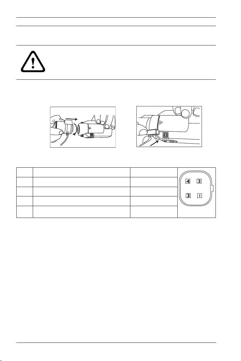
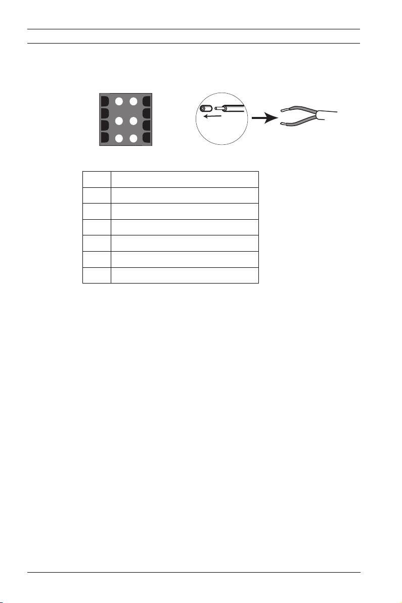
5.1 Lens mounting
Bosch
Figure 5.1 Mounting a lens
Figure 5.2 Lens connector
Pin Video iris lens DC iris lens
1 Supply (11.5V ±0.5, 50mA max.) Damp -
2 Not used Damp +
3 Video signal 1Vpp 1kOhm Drive +
4 Ground Drive -
Note
If a short circuit is detected on the lens connector, the message
LENS SHORT CIRCUIT is shown. The lens circuit is
automatically disabled to avoid internal damage. Remove the
lens connector and check the pin connections.
Bosch
AR18-10-B013 | v1.52 | 2011.06 Installation and Operation Manual Bosch Security Systems
Page 25
DinionHD 720p IP Camera Installation | en 25
5.2 Mounting the camera
The camera can be mounted either from the top or from the
bottom (1/4" 20 UNC thread).
Figure 5.3 Mounting a camera
CAUTION!
Do not expose the image sensors to direct sunlight.
Do not obstruct the free flow of air around the camera.
Bosch Security Systems Installation and Operation Manual AR18-10-B013 | v1.52 | 2011.06
Page 26
26 en | Installation DinionHD 720p IP Camera
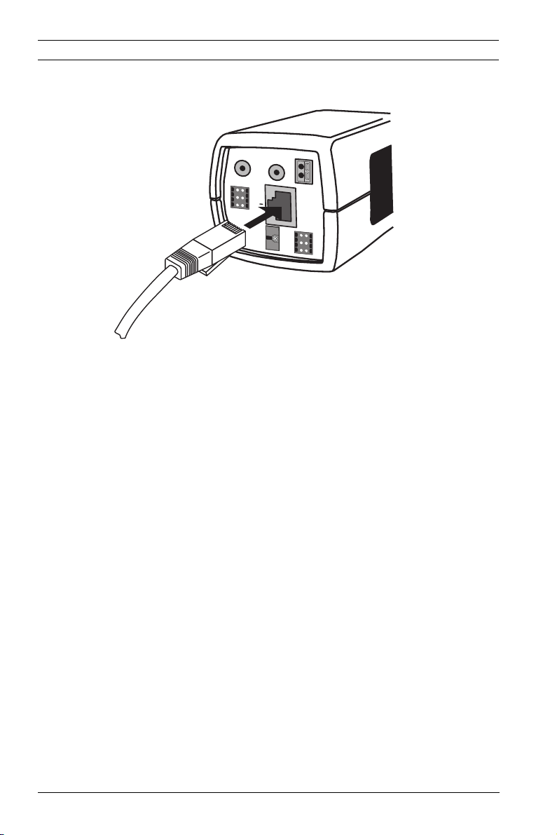
5.3 Network (and power) connector
AUDIO IN
AUDIO OUT
ALARM
E
1
4
T
2
5
H
3
6
P
o
E
SD
STP Cat 5e RJ45
Figure 5.4 Network connection
– Connect the camera to a 10/100 Base-T network.
– Use STP (Shielded Twisted Pair) Category 5e cable with
RJ45 connectors. The camera network socket is Auto MDIX
compliant.
– Power can be supplied to the camera via the Ethernet
cable compliant with the Power-over-Ethernet
(IEEE 802.3af) standard.
The multicolored LED beside the Ethernet connection indicates
Power (red), IP connection (green) and IP traffic (green
flashing). It can be disabled in the Installer menu.
By default, power is supplied to the camera via the Ethernet
cable, compliant with the Power-over-Ethernet standard.
–
+
12 VDC
24 VAC
DATA
1
4
2
5
3
6
AR18-10-B013 | v1.52 | 2011.06 Installation and Operation Manual Bosch Security Systems
Page 27
DinionHD 720p IP Camera Installation | en 27
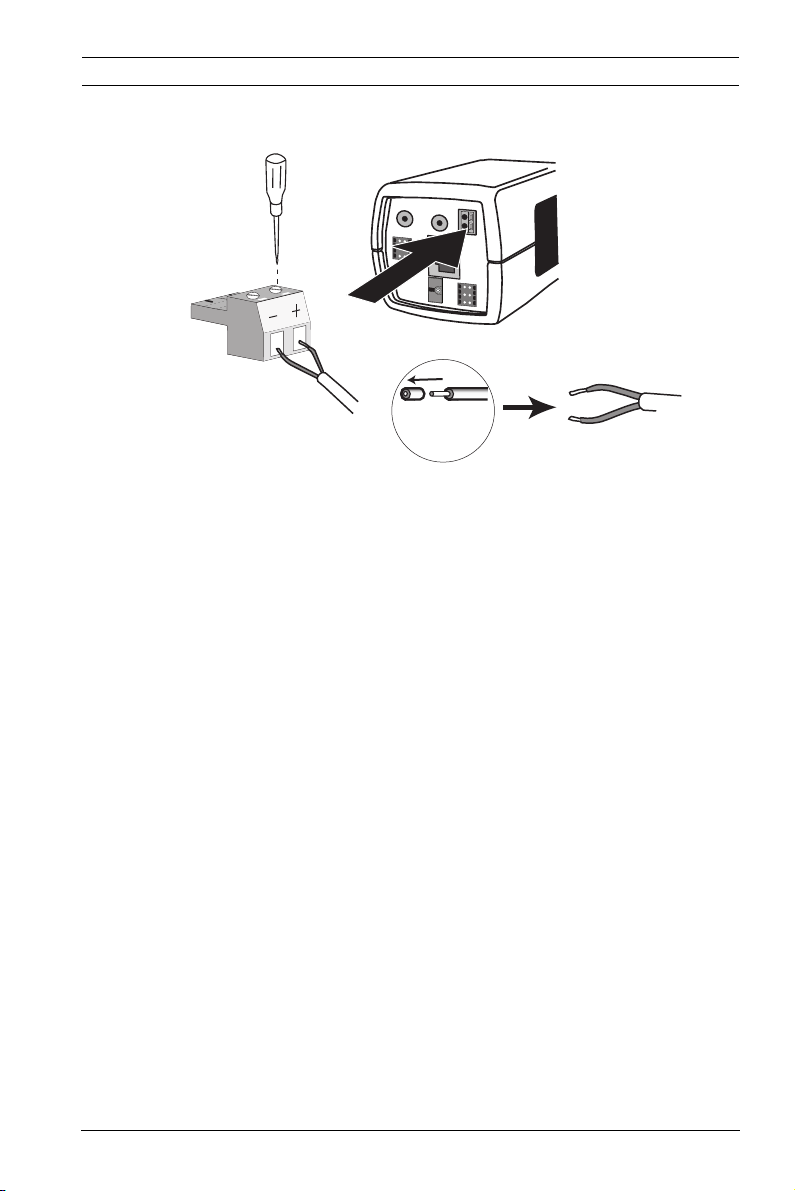
5.4 Power connector
AUDIO IN
AUDIO OUT
–
E
T
H
P
o
E
S
D
5 mm
0.2 in
+
12 VDC
24 VAC
DATA
1
4
2
5
3
6
A
L
A
R
M
1
4
2
5
3
6
Figure 5.5 Power connection
Connect power from a 24 VAC or 12 VDC class 2 power supply
as follows:
– Use AWG16 to 22 stranded wire or AWG16 to 26 solid
wire; cut back 5 mm (0.2 in) of insulation.
– Loosen the screws of the supplied 2-pole connector and
insert the wires.
– Tighten the screws and insert the 2-pole connector into
the power socket of the camera.
Bosch Security Systems Installation and Operation Manual AR18-10-B013 | v1.52 | 2011.06
Page 28
28 en | Installation DinionHD 720p IP Camera
5.5 Alarm and relay connector
Alarm
1
4
2
3
Figure 5.6 Alarm and relay connector pins
Pin Alarm socket
1 Alarm in 1
2 Alarm in 2
3 Relay out contact 1
4Ground
5Ground
6 Relay out contact 2
Alarm Input
– AWG 26-16 max.(0.13-1.5 mm2); cut back 5 mm (0.2 in) of
insulation.
– Impedence: Internal pull-up 10 kOhm to +5 VDC.
– Input voltage range: -5 VDC minimum to 40 VDC maximum.
– Input voltage treshold: low voltage 0.8 V maximum, high
voltage 2.4 V minimum.
– Configurable as active low or active high.
Use the alarm input to connect external alarm devices such as
door contacts or sensors. A zero potential make or break
contact can be used as the actuator (use a bounce-free contact
system).
5
6
5 mm
(0.2 in)
Relay output
– Max. wire diameter AWG 22-28 for both stranded and
solid; cut back 5 mm (0.2 in) of insulation.
– Output relay switching capability: Max voltage 30VAC or
+40 VDC. Max 0.5 A continuous, 10 VA.
– Max. 42 V allowed between camera ground and each of the
relay pins.
AR18-10-B013 | v1.52 | 2011.06 Installation and Operation Manual Bosch Security Systems
Page 29
DinionHD 720p IP Camera Installation | en 29
5.6 Audio connectors
Line
GND
AUDIO
IN
AU
D
IO OUT
–
ALARM
E
1
4
T
2
5
H
3
6
P
o
E
SD
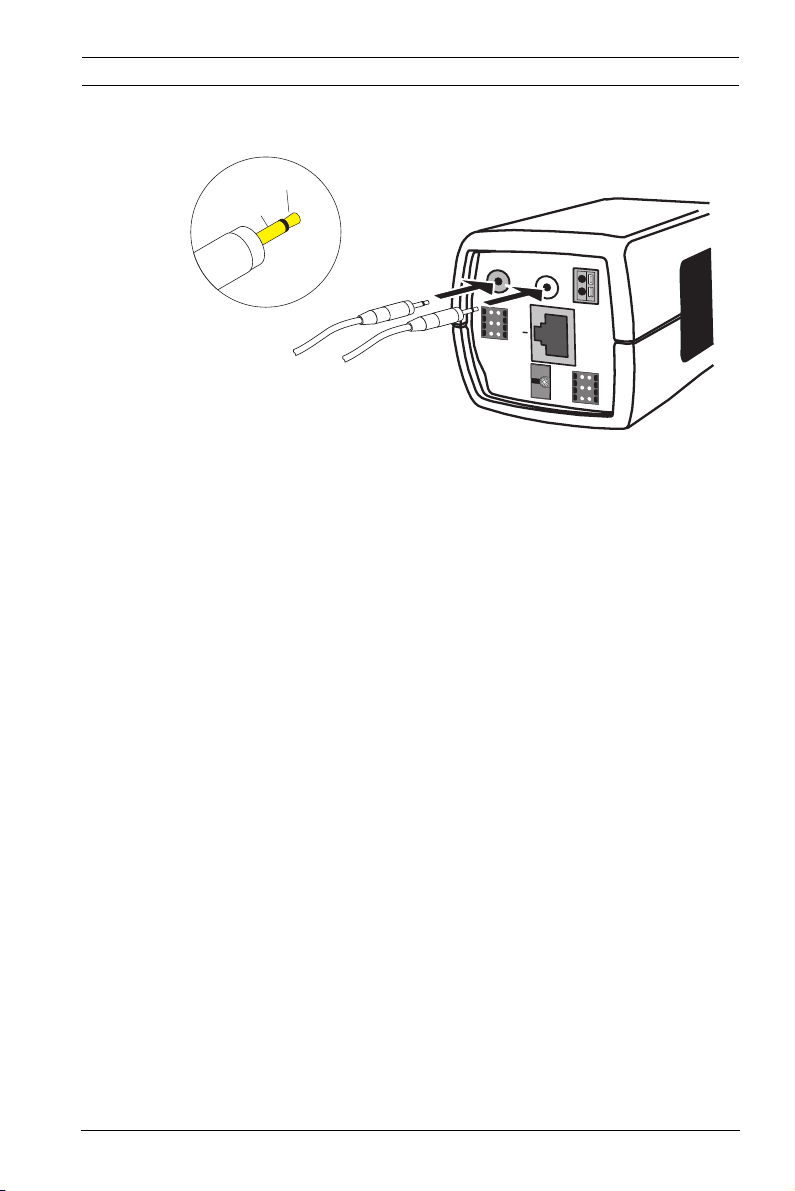
Figure 5.7 Audio connectors
Connect audio devices to the Audio In and Audio Out
connectors.
The unit has full-duplex mono audio. The two-way
communication can be used to connect a speaker or door
intercom system. The audio input signal is transmitted in sync.
with the video signal.
+
12 VDC
24 VAC
DATA
1
4
2
5
3
6
Audio input: Line input level (not suitable for direct
microphone signal); impedance 9 kOhm typical; 5.5 Vpp
maximum input voltage.
Audio output: Line output level (not suitable for direct speaker
connection); impedance 16 Ohm minimum; 3 Vpp maximum
output voltage.
Wiring: Shielded audio connection cable is advised. Observe
maximum cable lengths for audio line input and output levels.
Bosch Security Systems Installation and Operation Manual AR18-10-B013 | v1.52 | 2011.06
Page 30
30 en | Installation DinionHD 720p IP Camera
1
2
3
4
5
6
E
T
H
P
o
E
ALARM
AUDIO IN
AUDIO OUT
DATA
1
2
3
4
5
6
–
+
12 VDC
24 VAC
SD Card
SD
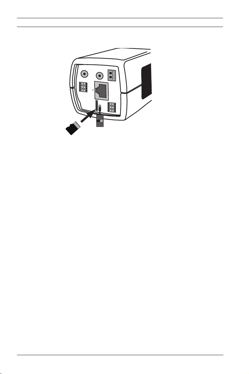
5.7 MicroSD card
Figure 5.8 Inserting an microSD card
1. Unscrew the microSD card slot cover.
2. With the connection pads to the left, slide the microSD
card into the slot until it locks in place.
3. Screw the cover into place to seal the slot.
AR18-10-B013 | v1.52 | 2011.06 Installation and Operation Manual Bosch Security Systems
Page 31

DinionHD 720p IP Camera Installation | en 31
5.8 Data connector
DATA
1
2
3
Figure 5.9 Data connector pins
Pin Data socket
1Ground
2RxD / Rx+
3CTS / Rx-
4Ground
5 TxD / Tx-
6 RTS / Tx+
The data connector is used to connect the control data coming
out of the camera to external devices. RS485, RS422, and
RS232 is supported by this data connection.
Note:
To ensure surge and electrostatic protection, keep the cable
length between the camera and external device to less than 3
meters.
4
5
6
5 mm
(0.2 in)
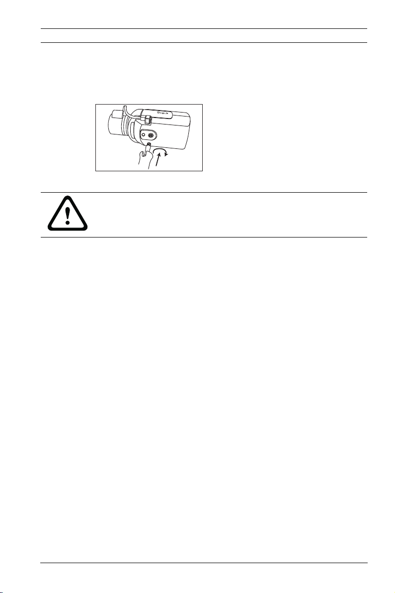
5.9 Back focus adjustment
To optimize picture sharpness in both bright and low-level
lighting, adjust the back focus. Use the camera's unique Lens
Wizard. This ensures that the object of interest always remains
in focus, even when focusing at the maximum lens iris opening
(for example, at night).
When back focusing zoom lenses, ensure the object of interest
remains in focus throughout the entire zoom range of the lens.
To adjust back focus:
1. Slide open the door panel at the side of the camera.
Bosch Security Systems Installation and Operation Manual AR18-10-B013 | v1.52 | 2011.06
Page 32

32 en | Installation DinionHD 720p IP Camera
Bosch
Bosch
2. Unlock the back focus locking button.
3. In a web browser, open the Len Wizard in the Camera/
Installer menu and select the wizard mode.
(Default path: http//192.168.0.1/lenswizard.htm)
4. Adjust the focal length on the lens as required.
5. Adjust the focus on the lens for your area of interest.
6. Turn the back focus adjustment to obtain the sharpest
picture.
Bosch
7. Lock the back focus locking button.
Bosch
8. Close the side door panel.
AR18-10-B013 | v1.52 | 2011.06 Installation and Operation Manual Bosch Security Systems
Page 33

DinionHD 720p IP Camera Installation | en 33
5.10 Reset button
AUDIO IN
AUDIO OUT
ALARM
E
1
4
T
2
5
H
3
6
P
VIDEO
o
E
SD
Figure 5.10 Reset button
With the power on, use a small pointed object to press and hold
the reset button for more than 10 seconds to restore the
factory defaults. This is useful to restore the default IP address
or to restore a previous version of the firmware if uploading a
new version fails.
–
+
12 VDC
24 VAC
DATA
1
4
2
5
3
6
Bosch Security Systems Installation and Operation Manual AR18-10-B013 | v1.52 | 2011.06
Page 34

34 en | Camera set-up DinionHD 720p IP Camera
6 Camera set-up
The camera normally provides an optimal picture without the
need for further adjustments. Configuration of the camera is
carried out via the network using a web browser. The camera
has a set-up menu in which basic installation settings (lens
wizard, IP address) can be accessed. To view this menu,
connect a laptop to the network connection of the camera.
6.1 Pre-defined modes
There are six pre-defined modes with settings to make
configuration easier. The modes are defined as follows;
1. 24-hour
Default installation mode to provide stable pictures over a
24-hour period. These settings are optimized for out-of-
the-box installation.
2. Traffic
Capture high-speed objects using default shutter in
variable lighting conditions.
3. Low light
Provide extra enhancement, such as AGC and SensUp to
make usable pictures in low-light conditions.
4. Smart BLC
Settings optimized to capture details in high contrast and
extremely bright-dark conditions.
5. Low noise
Enhancements are set to reduce picture noise. Useful
when conditionally refreshing IP storage systems because
reducing noise reduces the amount of storage required.
6. Infrared
Use this mode if the camera is viewing a scene lit by
infrared light.
Note:
Although the same user settings may have been made, the
camera may still behave differently in different modes.
AR18-10-B013 | v1.52 | 2011.06 Installation and Operation Manual Bosch Security Systems
Page 35

DinionHD 720p IP Camera Camera set-up | en 35
6.2 Day/Night switching
The camera is equipped with a motorized IR filter. The
mechanical IR filter can be removed in low-light or IR
illuminated applications by software configuration settings.
If Auto switching mode is selected, the camera automatically
switches the filter depending on the observed light level. The
switching level is programmable. In Auto switching mode the
camera prioritizes motion (the camera gives sharp images
without motion blur as long as the light level permits) or color
(the camera gives color pictures as long as the light level
permits). The camera recognizes IR illuminated scenes to
prevent unwanted switching to color mode.
There are four different methods of controlling the IR filter:
– via an alarm input,
– automatically, based on the observed light levels, or
– as part of the programmable mode profile.
Bosch Security Systems Installation and Operation Manual AR18-10-B013 | v1.52 | 2011.06
Page 36

36 en | Browser connection DinionHD 720p IP Camera
7 Browser connection
A computer with Microsoft Internet Explorer can be used to
receive live images from the camera, control cameras, and
replay stored sequences. The camera is configured over the
network using the browser (or via the supplied Configuration
Manager). The configuration options using the menu system of
the camera itself are limited to setting up the lens and network.
Note:
The camera can also be configured using the Bosch Video
Management System.
7.1 System requirements
– Microsoft Internet Explorer version 7.0 or higher
– Monitor: resolution at least 1024 × 768 pixels, 16 or 32 bit
color depth
– Sun JVM installed
– Intranet or Internet network access
The Web browser must be configured to enable Cookies to be
set from the IP address of the unit.
In Windows Vista, deactivate protected mode on the Security
tab under Internet Options.
Read the information in the System Requirements document
on the product DVD supplied and, if necessary, install the
required programs and controls.
To play back live video images, an appropriate ActiveX must be
installed on the computer. If necessary, install the Bosch Video
Client.
AR18-10-B013 | v1.52 | 2011.06 Installation and Operation Manual Bosch Security Systems
Page 37

DinionHD 720p IP Camera Browser connection | en 37
7.2 Establishing the connection
The camera must be assigned a valid IP address to operate on
your network. The default address pre-set at the factory is
192.168.0.1
1. Start the Web browser.
2. Enter the IP address of the camera as the URL.
Note:
If the connection is not established, the maximum number of
possible connections may already have been reached.
Depending on the device and network configuration, up to 25
web browsers, or 50 Bosch Video Client or Bosch Video
Management System connections are supported.
7.2.1 Password protection in camera
A camera offers the option of limiting access across various
authorization levels. If the camera is password-protected, a
message to enter the password appears.
1. Enter the user name and the associated password in the
appropriate fields.
2. Click OK. If the password is correct, the desired page is
displayed.
7.3 Protected network
If a RADIUS server is used for network access control (802.1x
authentication), the camera must be configured first. To
configure the camera for a Radius network, connect it directly
to a PC via a crossed network cable and configure the two
parameters, Identity and Password. Only after these have been
configured can communication with the camera via the network
occur.
Bosch Security Systems Installation and Operation Manual AR18-10-B013 | v1.52 | 2011.06
Page 38

38 en | Browser connection DinionHD 720p IP Camera
7.4 Connection established
When a connection is established, the LIVEPAGE is initially
displayed. The application title bar displays three items:
LIVEPAGE, RECORDINGS, SETTINGS.
Note:
The RECORDINGS link is only visible if a direct iSCSI or
microSD card has been configured for recording. (With VRM
recording this option is not active.)
Figure 7.1 Livepage
7.4.1 LIVEPAGE
The LIVEPAGE is used to display and control the video stream.
Refer to Section 10 Operation via the browser, page 110 for more
information.
7.4.2 RECORDINGS
Click RECORDINGS in the application title bar to open the
playback page. Refer to Section 10 Operation via the browser,
page 110 for more information.
AR18-10-B013 | v1.52 | 2011.06 Installation and Operation Manual Bosch Security Systems
Page 39

DinionHD 720p IP Camera Browser connection | en 39
7.4.3 SETTINGS
Click SETTINGS in the application title bar to configure the
camera and the application interface. A new page containing
the configuration menu is opened. All settings are stored in the
camera memory so that they are retained, even if the power is
interrupted.
Changes that influence the fundamental functioning of the unit
(for example, firmware updates) can only be made using the
configuration menu.
The configuration menu tree allows all parameters of the unit to
be configured. The configuration menu is divided into Basic
Mode and Advanced Mode.
Refer to Section 8 Basic Mode, page 40 for more information on
basic settings; refer to Section 9 Advanced Mode, page 45 for
more information on advanced settings.
Note:
It is recommended that only expert users or system
administrators use the Advanced Mode.
Bosch Security Systems Installation and Operation Manual AR18-10-B013 | v1.52 | 2011.06
Page 40

40 en | Basic Mode DinionHD 720p IP Camera
8Basic Mode
8.1 Basic Mode menu tree
The basic mode configuration menu allows a set of basic
camera parameters to be configured.
Basic Mode
> Device Access
> Date/Time
> Network
> Encoder
> Audio
> Recording
> System Overview
To view the current settings:
1. If necessary, click the Basic Mode menu to expand it. The
sub-menus are displayed.
2. Click a sub-menu. The corresponding page is opened.
The settings are changed by entering new values or by selecting
a pre-defined value in a list field.
Saving changes
After making changes in a window, click Set to send the new
settings to the device and save them there.
Clicking Set saves only the settings in the current window.
Changes in any other windows are ignored.
Click SETTINGS in the applications title bar to close the
window without saving the changes.
Note:
Device time settings are lost after 1 hour without power.
Note:
When entering names do not use any special characters, for
example &. Special characters are not supported by the internal
recording management system.
AR18-10-B013 | v1.52 | 2011.06 Installation and Operation Manual Bosch Security Systems
Page 41

DinionHD 720p IP Camera Basic Mode | en 41
8.2 Device Access
8.2.1 Camera name
Assign a name to assist in identification. This name simplifies
the management of multiple devices in more extensive systems.
The name is used for remote identification, for example, in the
event of an alarm. Enter a name that makes it as easy as
possible to identify the location unambiguously.
8.2.2 Password
A password prevents unauthorized access to the device. The
device recognizes three authorization levels: service, user, and
live.
– service is the highest authorization level. Entering the
correct password gives access to all the functions of the
camera and allows all configuration settings to be
changed.
– user is the middle authorization level. This user can
operate the device, play back recordings, and also control
a camera but cannot change the configuration.
– live is the lowest authorization level. It can only be used to
view the live video image and switch between the different
live image displays.
Use the various authorization levels to limit access. Proper
password protection is only guaranteed if all higher
authorization levels are also protected with a password. For
example, if a live password is assigned, a service and a user
password should also be set. When assigning passwords,
always start from the highest authorization level, service, and
use different passwords.
Password
Define and change a separate password for each level while
logged in as service or if the device is not protected by a
password. Enter the password (19 characters maximum) for
the selected level.
Bosch Security Systems Installation and Operation Manual AR18-10-B013 | v1.52 | 2011.06
Page 42

42 en | Basic Mode DinionHD 720p IP Camera
Confirm password
Re-enter the new password to ensure that there are no typing
mistakes.
The new password is only saved after clicking Set. Therefore,
click Set immediately after entering and confirming the
password, even if assigning a password at another level.
8.3 Date/Time
Device date, time and zone
If there are multiple devices operating in the system or
network, it is important to synchronize their internal clocks. For
example, it is only possible to identify and correctly evaluate
simultaneous recordings when all devices are operating on the
same time. Device time, date and time zone are shown.
– Click Sync to PC to apply the system time from your
computer to the device.
Time server IP address
The camera can receive the time signal from a time server using
various time server protocols and then use it to set the internal
clock. The device polls the time signal automatically once every
minute. Enter the IP address of a time server.
Time server type
Select the protocol that is supported by the selected time
server. It is recommended to select the SNTP server protocol.
This protocol provides high accuracy and is required for special
applications and future function extensions. Select Time server
if the server uses the RFC 868 protocol.
Note:
It is important to ensure that the date/time is correct for
recording. An incorrect date/time setting could prevent correct
recording.
AR18-10-B013 | v1.52 | 2011.06 Installation and Operation Manual Bosch Security Systems
Page 43

DinionHD 720p IP Camera Basic Mode | en 43
8.4 Network
Use the settings on this page to integrate the device into a
network. Some changes only take effect after a reboot. In this
case, the Set button changes to Set and Reboot.
1. Make the desired changes.
2. Click Set and Reboot.
– The device is rebooted and the changed settings are
activated. If the IP address, subnet mask, or gateway
address is changed, then the device is only available
under the new addresses after the reboot.
DHCP
If the network has a DHCP server for dynamic IP address
allocation, set this parameter to On to activate the automatic
acceptance of DHCP-assigned IP addresses.
Note:
Certain applications (for example, Bosch Video Management
System) use the IP address for the unique assignment of the
device. If using these applications, the DHCP server must
support the fixed assignment between IP address and MAC
address, and must be appropriately set up so that, once an IP
address is assigned, it is retained each time the system is
rebooted.
IP address
Enter the desired IP address for the camera. The IP address
must be valid for the network.
Subnet mask
Enter the appropriate subnet mask for the set IP address.
Gateway address
Enter the IP address of the gateway to establish a connection to
a remote location in a different subnet. Otherwise, this field can
remain empty (0.0.0.0).
Bosch Security Systems Installation and Operation Manual AR18-10-B013 | v1.52 | 2011.06
Page 44

44 en | Basic Mode DinionHD 720p IP Camera
8.5 Encoder
Select a profile for encoding the video signal. Pre-programmed
profiles are available that give priority to different parameters.
When a profile is selected, its details are displayed.
8.6 Audio
Switch the camera audio On or Off. Adjust the input and output
levels with the sliders.
8.7 Recording
Record the images from the camera to a storage medium. For
long-term authoritative images, it is essential to use VRM or an
appropriately sized iSCSI system.
8.7.1 Storage medium
1. Select the required storage medium from the list.
2. Click Start to start recording or Stop to end recording.
8.8 System Overview
This page provides general information on the hardware and
firmware system, including version numbers. No items can be
changed on this page but they can be copied for information
purposes when troubleshooting.
AR18-10-B013 | v1.52 | 2011.06 Installation and Operation Manual Bosch Security Systems
Page 45

DinionHD 720p IP Camera Advanced Mode | en 45
9 Advanced Mode
9.1 Advanced Mode menu tree
The advanced mode configuration menu contains all camera
parameters that can be configured.
Advanced Mode
> General
> Web Interface
> Camera
> Recording
> Alarm
> Interfaces
> Network Access
> Service
To view the current settings:
1. Click the Advanced Mode menu to expand it. The
associated menu sub-headings are displayed.
2. Click a menu sub-heading to expand it.
3. Click a sub-menu. The corresponding page is opened.
The settings are changed by entering new values or by selecting
a pre-defined value in a list field.
Saving changes
Picture settings change immediately and do not have to be
saved. After making changes in other windows, click Set to
send the new settings to the device and save them there.
Clicking Set saves only the settings in the current window.
Changes in any other windows are ignored.
Click SETTINGS in the applications title bar to close the
window without saving the changes made.
Bosch Security Systems Installation and Operation Manual AR18-10-B013 | v1.52 | 2011.06
Page 46

46 en | Advanced Mode DinionHD 720p IP Camera
9.2 General
General
> Identification
> Password
> Date/Time
> Display Stamping
9.2.1 Identification
Camera ID
Each device should be assigned a unique identifier that can be
entered here as an additional means of identification.
Camera name
Assign a name to assist in identification. This name simplifies
the management of multiple devices in more extensive systems.
The name is used for remote identification, for example, in the
event of an alarm. Enter a name that makes it as easy as
possible to identify the location unambiguously.
Initiator extension
Add text to an initiator name to make identification easier in
large iSCSI systems. This text is added to the initiator name,
separated from it by a full stop (period).
9.2.2 Password
A password prevents unauthorized access to the device. The
device recognizes three authorization levels: service, user, and
live.
– service is the highest authorization level. Entering the
correct password gives access to all the functions of the
camera and allows all configuration settings to be
changed.
– user is the middle authorization level. This user can
operate the device, play back recordings, and also control
a camera but cannot change the configuration.
AR18-10-B013 | v1.52 | 2011.06 Installation and Operation Manual Bosch Security Systems
Page 47

DinionHD 720p IP Camera Advanced Mode | en 47
– live is the lowest authorization level. It can only be used to
view the live video image and switch between the different
live image displays.
Use the various authorization levels to limit access. Proper
password protection is only guaranteed if all higher
authorization levels are also protected with a password. For
example, if a live password is assigned, a service and a user
password should also be set. When assigning passwords,
always start from the highest authorization level, service, and
use different passwords.
Password
Define and change a separate password for each level while
logged in as service or if the device is not protected by a
password. Enter the password (19 characters maximum) for
the selected level.
Confirm password
Re-enter the new password to ensure that there are no typing
mistakes.
The new password is only saved after clicking Set. Therefore,
click Set immediately after entering and confirming the
password, even if assigning a password at another level.
Bosch Security Systems Installation and Operation Manual AR18-10-B013 | v1.52 | 2011.06
Page 48

48 en | Advanced Mode DinionHD 720p IP Camera
9.2.3 Date/Time
Date format
Select the required date format.
Device date / Device time
If there are multiple devices operating in your system or
network, it is important to synchronize their internal clocks. For
example, it is only possible to identify and correctly evaluate
simultaneous recordings when all devices are operating on the
same time.
1. Enter the current date. Since the device time is controlled
by the internal clock, it is not necessary to enter the day of
the week – it is added automatically.
2. Enter the current time or click Sync to PC to apply the
system time from your computer to the device.
Note:
It is important to ensure that the date/time is correct for
recording. An incorrect date/time setting could prevent correct
recording.
Device time zone
Select the time zone in which the system is located.
Daylight saving time
The internal clock can switch automatically between normal
and daylight saving time (DST). The device already contains the
data for DST switch-overs up to the year 2015. Use this data or
create alternative time saving data, if required.
First, check the time zone setting. If it is not correct, select the
appropriate time zone for the system:
1. Click Set.
2. Click Details. A new window opens showing an empty
table.
3. Click Generate to fill the table with the preset values from
the camera.
4. Select the region or the city which is closest to the
system's location from the list box below the table.
AR18-10-B013 | v1.52 | 2011.06 Installation and Operation Manual Bosch Security Systems
Page 49

DinionHD 720p IP Camera Advanced Mode | en 49
5. Click one of the entries in the table to make changes. The
entry is highlighted.
6. Click Delete to remove the entry from the table.
7. Choose other values from the list boxes under the table, to
change the selected entry. Changes are immediate.
8. If there are empty lines at the bottom of the table, for
example after deletions, add new data by marking the row
and selecting values from the list boxes.
9. When finished, click OK to save and activate the table.
Note:
If a table is not created, there is no automatic switching. When
editing the table, note that values occur in linked pairs (DST
start and end dates).
Time server IP address
The camera can receive the time signal from a time server using
various time server protocols and then use it to set the internal
clock. The device polls the time signal automatically once every
minute. Enter the IP address of a time server.
Time server type
Select the protocol that is supported by the selected time
server. It is recommended to select the SNTP server protocol.
This protocol provides high accuracy and is required for special
applications and future function extensions. Select Time server
if the server uses the RFC 868 protocol.
9.2.4 Display Stamping
Various overlays or stamps in the video image provide
important supplementary information. These overlays can be
enabled individually and arranged on the image in a clear
manner.
Camera name stamping
This field sets the position of the camera name overlay. It can
be displayed at the Top, at the Bottom, or at a position of
choice using the Custom option, or it can be set to Off for no
overlay information.
Bosch Security Systems Installation and Operation Manual AR18-10-B013 | v1.52 | 2011.06
Page 50

50 en | Advanced Mode DinionHD 720p IP Camera
If the Custom option is selected, enter values in the X and Y
position fields.
Time stamping
This field sets the position of the time and date overlay. It can
be displayed at the Top, at the Bottom, or at a position of
choice using the Custom option, or it can be set to Off for no
overlay information.
If the Custom option is selected, enter values in the X and Y
position fields.
Display milliseconds
If necessary, display milliseconds for Time stamping. This
information can be useful for recorded video images; however,
it does increase the processor's computing time. Select Off if
displaying milliseconds is not needed.
Alarm mode stamping
Select On for a text message to be overlaid in the event of an
alarm. It can be displayed at a position of choice using the
Custom option, or it can be set to Off for no overlay
information.
If the Custom option is selected, enter values in the X and Y
position fields.
Alarm message
Enter the message to be displayed on the image in the event of
an alarm. The maximum text length is 31 characters.
Video watermarking
Select On for the transmitted video images to be watermarked.
After activation, all images are marked with an icon. The icon
indicates if the sequence (live or saved) has been manipulated.
AR18-10-B013 | v1.52 | 2011.06 Installation and Operation Manual Bosch Security Systems
Page 51

DinionHD 720p IP Camera Advanced Mode | en 51
9.3 Web Interface
Web Interface
> Appearance
> LIVEPAGE
Functions
> Logging
9.3.1 Appearance
Adapt the appearance of the web interface and change the
website language to meet your requirements. If necessary,
replace the company's logo (top right) and the device name
(top left) in the top part of the window with individual graphics.
Either GIF or JPEG images can be used. The file paths must
correspond to the access mode (for example,
C:\Images\Logo.gif for access to local files or http://
www.myhostname.com/images/logo.gif for access via the
Internet/Intranet). For access via the Internet/Intranet, there
must be a connection in order to display the image. The image
files are not stored on the camera.
To restore the original graphics, delete the entries in the
Company logo and Device logo fields.
Website language
Select the language for the user interface here.
Company logo
Enter the path to a suitable image in this field. The image can
be stored on a local computer, a local network, or at an Internet
address.
Device logo
Enter the path for a suitable image for the device logo in this
field. The image can be stored on a local computer, a local
network, or at an Internet address.
Bosch Security Systems Installation and Operation Manual AR18-10-B013 | v1.52 | 2011.06
Page 52

52 en | Advanced Mode DinionHD 720p IP Camera
9.3.2 LIVEPAGE Functions
In this window, adapt the Livepage functions to meet your
requirements. Choose from a variety of different options for
displaying information and controls.
1. Mark the check boxes for the functions to be displayed on
the Livepage. The selected elements are checked.
2. Check the Livepage to see how the desired items are
available.
Transmit audio
When selected, the audio from the camera (if on) is sent to the
computer. This setting applies only to the PC from which this
has been activated or deactivated.
Show alarm inputs
The alarm inputs are displayed next to the video image as icons
along with their assigned names. If an alarm is active, the
corresponding icon changes color. Uncheck the box to remove
the alarm icons from the Livepage.
Show relay outputs
The relay output is shown next to the video image as an icon
along with its assigned name. If a relay is switched, the icon
changes color. Uncheck the box to remove the relay icons from
the Livepage.
Show VCA trajectories
The trajectories (motion lines of objects) from the video
content analysis are displayed in the live video image if a
corresponding analysis type is activated. Uncheck the box to
hide the trajectories on the Livepage video.
Show VCA metadata
When video content analysis (VCA) is activated, additional
information is displayed in the live video stream. For example,
in Motion+ mode, the sensor areas for motion detection are
marked. Uncheck the box to hide the metadata on the Livepage
video.
AR18-10-B013 | v1.52 | 2011.06 Installation and Operation Manual Bosch Security Systems
Page 53

DinionHD 720p IP Camera Advanced Mode | en 53
Show event log
The event messages are displayed with the date and time in a
field next to the video image. Uncheck the box to hide the event
log on the Livepage.
Show system log
The system messages are displayed with the date and time in a
field next to the video image and provide information about the
establishment and termination of connections, etc. Uncheck
the box to hide the system log on the Livepage.
Allow snapshots
Specify whether the icon for saving individual images should be
displayed below the live image. Individual images can only be
saved if this icon is visible.
Allow local recording
Specify whether the icon for saving video sequences on the
local memory should be displayed below the live image. Video
sequences can only be saved if this icon is visible.
Path for JPEG and video files
Enter the path for the storage location of individual images and
video sequences saved from the Livepage. If necessary, click
Browse to find a suitable folder.
9.3.3 Logging
Save event log
Select this option to save event messages in a text file on the
local computer. This file can be viewed, edited, and printed
with any text editor or standard office software.
File for event log
Enter the path for saving the event log here. If necessary, click
Browse to find a suitable folder.
Save system log
Select this option to save system messages in a text file on the
local computer. This file can be viewed, edited, and printed
with any text editor or standard office software.
Bosch Security Systems Installation and Operation Manual AR18-10-B013 | v1.52 | 2011.06
Page 54

54 en | Advanced Mode DinionHD 720p IP Camera
File for system log
Enter the path for saving the system log here. If necessary, click
Browse to find a suitable folder.
AR18-10-B013 | v1.52 | 2011.06 Installation and Operation Manual Bosch Security Systems
Page 55

DinionHD 720p IP Camera Advanced Mode | en 55
9.4 Camera
Camera
> Picture Settings
> Mode
> ALC
> Shutter/AGC
> Day/night
> Enhance
> Color
> Encoder Profile
> Encoder Streams
> Privacy Masks
> Audio
> Installer Menu
If the camera is in monochrome mode, all color-related menu
items are disabled and cannot be accessed.
9.4.1 Mode
Pre-defined modes
The camera has six pre-programmed operating modes that can
be selected in the Mode menu.
The modes are defined as follows:
1. 24-hour
Default installation mode to provide stable pictures over a
24-hour period. These settings are optimized for out-ofthe-box installation.
2. Traffic
Capture high-speed objects using default shutter in
variable lighting conditions.
3. Low light
Provide extra enhancement, such as AGC and SensUp to
make usable pictures in low-light conditions.
Bosch Security Systems Installation and Operation Manual AR18-10-B013 | v1.52 | 2011.06
Page 56

56 en | Advanced Mode DinionHD 720p IP Camera
4. Smart BLC
Settings optimized to capture details in high contrast and
extremely bright-dark conditions.
5. Low noise
Enhancements are set to reduce picture noise. Useful
when conditionally refreshing IP storage systems because
reducing noise reduces the amount of storage required.
6. Infrared
Use this mode if the camera is viewing a scene lit by
infrared light.
These modes are pre-programmed by default but can be
adjusted according to personal preferences. The Mode menu
allows selection and set-up of picture enhancement functions
for each mode. If the changes are not satisfactory, restore the
default values for the mode.
Mode ID
Enter a name for the selected mode.
Copy mode to
Select a mode to copy the current mode to.
Restore Mode Defaults
Click to restore the factory defaults. A confirmation screen
appears. Allow 5 seconds for the camera to optimize the
picture after a mode reset.
AR18-10-B013 | v1.52 | 2011.06 Installation and Operation Manual Bosch Security Systems
Page 57

DinionHD 720p IP Camera Advanced Mode | en 57
9.4.2 ALC
ALC level
Adjust the video output level (-15 to 0 to +15).
Select the range within which the ALC will operate. A positive
value is more useful for low-light conditions; a negative value is
more useful for very bright conditions.
Some ALC adjustment may improve scene content when Smart/
BLC is enabled.
Peak average
Adjust the balance between peak and average video control
(-15 to 0 to +15). At -15 the camera controls the average video
level, at +15 the camera controls the peak video level.
A negative value gives more priority to average light levels; a
positive value gives more priority to peak light levels. Video iris
lens: choose an average level for best results (peak settings
may cause oscillations).
Speed
Adjust the speed of the video level control loop (Slow, Medium,
or Fast). For most scenes it should remain at the default value.
9.4.3 Shutter/AGC
Shutter
– Fixed — allows a user-defined shutter speed.
– AES (auto-shutter) — the camera automatically sets the
optimum shutter speed. The camera tries to maintain the
selected default shutter speed as long as the light level of
the scene permits.
Default shutter / Fixed shutter
Select the shutter speed (1/25, 1/50, 1/100, [1/30, 1/60, 1/
120] 1/250, 1/500, 1/1000, 1/2000, 1/5000, 1/10K) for the
default (AES) or fixed value.
In AES mode, the camera tries to maintain the selected shutter
speed as long as the light level of the scene is high enough.
In Fixed mode, select the shutter speed.
Bosch Security Systems Installation and Operation Manual AR18-10-B013 | v1.52 | 2011.06
Page 58

58 en | Advanced Mode DinionHD 720p IP Camera
Actual shutter
Displays the actual shutter value from the camera to help
compare lighting levels and optimum shutter speed during setup.
Sensitivity up
In AES mode, selects the factor by which the sensitivity of the
camera is increased (OFF, 2x, 3x, etc. to a maximum of 10x).
Note:
If Sensitivity up is active, some noise or spots may appear in
the picture. This is normal camera behavior. Sensitivity up may
cause some motion blur on moving objects.
Gain
AGC - the camera automatically sets the gain to the lowest
possible value needed to maintain a good picture.
Fixed - sets Fixed gain value.
Maximum gain / Fixed gain
Selects the maximum value the gain can have during AGC
operation (0 to 30 dB).
Selects the gain setting for Fixed gain operation (0 is no gain).
Actual gain
Displays the actual AGC value from the camera to help compare
gain level with lighting levels and picture performance.
AR18-10-B013 | v1.52 | 2011.06 Installation and Operation Manual Bosch Security Systems
Page 59

DinionHD 720p IP Camera Advanced Mode | en 59
9.4.4 Day/night
The Day/Night camera is equipped with a motorized IR
(infrared) filter. The IR filter can be removed in low-light or IRilluminated applications. There are four different methods of
switching:
– via the alarm input,
– as part of the programmable mode profile,
– automatically, based on the observed light levels, or
– via the settings page.
Note:
For reliable Day/Night switching with an external IR illuminator,
synchronize the switching of the IR filter in the camera with the
IR illuminator using an alarm input port.
Day/night
Auto - the camera switches the IR cut-off filter on and off
depending on the scene illumination level.
Monochrome - the IR cut-off filter is removed, giving full IR
sensitivity.
Color - the camera always produces a color signal regardless of
light levels.
Switch level
Set the video Switch level at which the camera in Auto mode
switches to monochrome operation (-15 to 0 to +15).
A low (negative) value means that the camera switches to
monochrome at a lower light level. A high (positive) value
means that the camera switches to monochrome at a higher
light level.
Priority
In Auto switching mode, set the camera priority to either:
– Color: the camera gives color pictures as long as the light
level permits.
– Motion: the camera gives sharp images without motion
blur as long as the light level permits (it switches to
monochrome earlier than it would with Color priority).
Bosch Security Systems Installation and Operation Manual AR18-10-B013 | v1.52 | 2011.06
Page 60

60 en | Advanced Mode DinionHD 720p IP Camera
IR contrast
There are two modes for IR contrast:
– Enhanced: the camera optimizes contrast in applications
with high IR illumination levels. Select this mode for IR
(730 to 940 nm) light sources and for scenes with grass
and green foliage.
– Normal: the camera optimizes contrast in mono
applications with visible light illumination.
AR18-10-B013 | v1.52 | 2011.06 Installation and Operation Manual Bosch Security Systems
Page 61

DinionHD 720p IP Camera Advanced Mode | en 61
9.4.5 Enhance
Dynamic engine
– Off: turns off all automatic scene detail and enhancements
(only recommended for testing).
– XF Dynamic: extra internal processing is enabled for low-
light applications (traffic, etc.).
– Smart BLC: BLC window and weighting factor are
automatically defined. Camera dynamically adjusts these
for changing light conditions.
Auto black
Auto black ON automatically increases the visibility of details
even when scene contrast is less than full-range due to mist,
fog, etc.
Sharpness level
Adjusts the black level between -15 and +15. Zero position of
slider corresponds to the factory default black level.
A low (negative) value makes the picture less sharp. Increasing
sharpness brings out more detail. Extra sharpness can enhance
the details of license plates, facial features and the edges of
certain surfaces.
Dynamic noise reduction
In AUTO mode the camera automatically reduces the noise in
the picture. This may cause some motion blur on exceptionally
fast moving objects immediately in front of the camera. This can
be corrected by widening the field of view or selecting Off.
Bosch Security Systems Installation and Operation Manual AR18-10-B013 | v1.52 | 2011.06
Page 62

62 en | Advanced Mode DinionHD 720p IP Camera
9.4.6 Color
White balance
– ATW: Auto tracking white balance allows the camera to
continually adjust for optimal color reproduction.
– AWB hold: Puts ATW on hold and saves the color settings.
–In Manual mode the Red, Green, and Blue gain can be
manually set to a desired position.
Speed
Adjust the speed (Fast, Medium or Slow) of the white balance
control loop.
R-gain
Offsets factory white point alignment (reducing red introduces
more cyan).
ATW and AWBhold (-5 to +5): adjusts the Red gain to optimize
the white point.
Manual (-50 to +50): adjusts the Red gain.
B-gain
Offsets factory white point alignment (reducing blue introduces
more yellow).
AWBhold (-5 to +5): adjusts the B gain to optimize the white
point.
Manual (-50 to +50): adjusts the Blue gain.
G-gain
Manual (-50 to +50): adjusts the Green gain.
It is only necessary to change the white point offset for special
scene conditions.
Saturation
Adjusts the color saturation; -15 gives a monochrome image.
AR18-10-B013 | v1.52 | 2011.06 Installation and Operation Manual Bosch Security Systems
Page 63

DinionHD 720p IP Camera Advanced Mode | en 63
9.4.7 Encoder Profile
Adapt the video data transmission to the operating environment
(network structure, bandwidth, data structures). The camera
simultaneously generates two H.264 video streams, an I-frame
only stream and an M-JPEG stream. Select the compression
settings of these streams individually, for example, one setting
for transmissions to the Internet and one for LAN connections.
The settings are made individually for each stream.
Pre-programmed profiles
Eight definable profiles are available. The pre-programmed
profiles give priority to different parameters.
– HD high quality / low latency
High resolution for high bandwidth connections
– HD high quality
High resolution with lower data rate
– HD low bandwidth
High resolution for low bandwidth connections
– SD high quality / low latency
4CIF/D1 resolution for connections at 4000 kbps maximum
– SD high quality
CIF resolution for connections at 3000 kbps maximum
– SD low bandwidth
CIF resolution for connections at 1500 kbps maximum
– DSL
CIF resolution for connections at 500 kbps maximum
– ISDN (2B)
CIF resolution for connections at 100 kbps maximum
Bosch Security Systems Installation and Operation Manual AR18-10-B013 | v1.52 | 2011.06
Page 64

64 en | Advanced Mode DinionHD 720p IP Camera
Profile Configuration
Profiles can be configured for use with the H.264 settings of
encoder streams. Select a profile by clicking the appropriate
tab. Change the name of a profile and individual parameter
values within a profile.
Profiles are rather complex. They include a number of
parameters that interact with one another, so it is generally
best to use the default profiles. Only change a profile if
completely familiar with all the configuration options.
The parameters as a group constitute a profile and are
dependent on one another. If a setting outside the permitted
range for a parameter is entered, the nearest valid value is
substituted when the settings are saved.
Profile name
Enter a new name for the profile here. (Do not use any special
characters, for example &.)
Target bit rate
To optimize utilization of the bandwidth in the network, limit
the bit rate for the camera. The target bit rate should be set
according to the desired picture quality for typical scenes with
no excessive motion.
For complex images or frequent changes of image content due
to frequent movements, this limit can temporarily be exceeded
up to the value entered in the Maximum bit rate field.
Maximum bit rate
This maximum bit rate is not exceeded under any
circumstances. Depending on the video quality settings for the
I-frames and P-frames, this can result in individual images being
skipped.
The value entered here must be at least 10% higher than the
value entered in the Target bit rate field. If the value entered
here is too low, it is automatically adjusted.
Encoding interval
The Encoding interval slider determines the interval at which
images are encoded and transmitted. This can be particularly
AR18-10-B013 | v1.52 | 2011.06 Installation and Operation Manual Bosch Security Systems
Page 65

DinionHD 720p IP Camera Advanced Mode | en 65
advantageous with low bandwidths. The image rate in ips
(images per second) is displayed next to the slider.
Video resolution
Select the desired resolution for the video image. The following
resolutions are available:
– CIF
352 × 240 pixels
– 4CIF/D1
704 × 480 pixels
– 720p
1280 × 720 pixels
Note:
The video resolution set here is ignored by HD streams.
Expert Settings
if necessary, use the expert settings to adapt the I-frame quality
and the P-frame quality to specific requirements. The setting is
based on the H.264 quantization parameter (QP).
GOP structure
Select the structure you require for the Group of Pictures.
Depending on whether you place greater priority on having the
lowest possible delay (IP frames only) or using as little
bandwidth possible, you choose IP, IBP or IBBP.
I-frame distance
Use the slider to set the distance between I-frames to Auto or
to between 3 and 60. An entry of 3 means that every third
image is an I-frame.The lower the number, the more I-frames
are generated.
I-frame quality
This setting sets the image quality of the I-frames. Select Auto
to ensure that the maximum bit rate is not exceeded. Auto
automatically changes the I-frame quality to the settings for the
P-frame image quality.
Bosch Security Systems Installation and Operation Manual AR18-10-B013 | v1.52 | 2011.06
Page 66

66 en | Advanced Mode DinionHD 720p IP Camera
P-frame quality
This setting adjusts the maximum image quality of the P-frames.
Auto automatically adjusts to the optimum combination of
movement and image definition (focus). The value 9 represents
maximum image quality, a value of 51 represents minimum
quality. With the slide control, define a control range from a
chosen value to 51. The encoder delivers the best possible
quality within this control range while maintaining the
maximum bit rate.
Default
Click Default to return the profile to the factory default values.
AR18-10-B013 | v1.52 | 2011.06 Installation and Operation Manual Bosch Security Systems
Page 67

DinionHD 720p IP Camera Advanced Mode | en 67
9.4.8 Encoder Streams
Select H.264 Settings
1. The codec algorithm for stream 1 is always:
– H.264 MP 720p25/30 fixed
2. Select the codec algorithm for stream 2. The following are
available:
– Copy Stream 1
– H.264 BP+ bit-rate-limited
– H.264 MP SD
3. Select the Non-recording profile for each stream from the
eight profiles that have been defined. This profile is used
when a stream is not used for recording. When a stream is
used for recording, the profile selected on the Recording
Profiles page is used.
Preview >>
Previews of streams 1 and 2 can be shown.
1. Click Preview >> to display a preview of the video for
streams 1 and 2. the current profile is shown above the
preview.
2. Click 1:1 Live View below a preview to open a viewing
window for that stream. Various additional items of
information are shown across the top of the window.
3. Click Preview << to close the preview displays.
Note:
Deactivate the display of the video images if the performance of
the computer is adversely affected by the decoding of the data
stream.
JPEG stream
Set the parmeters for the M-JPEG stream.
– Select the Max. frame rate in images per second (IPS).
–The Picture quality slider allows adjustment of the
M-JPEG image quality from Low to High.
Bosch Security Systems Installation and Operation Manual AR18-10-B013 | v1.52 | 2011.06
Page 68

68 en | Advanced Mode DinionHD 720p IP Camera
Note:
The JPEG resolution follows the highest resolution setting of
either stream 1 or stream 2. The M-JPEG frame rate can vary
depending on system loading.
9.4.9 Privacy Masks
Four privacy mask areas can be defined. The activated masked
areas are filled with the selected pattern in live view.
1. Select the pattern to be used for all masks (Gray).
2. Check the box of the mask you wish to activate.
3. Use the mouse to define the area for each of the masks.
9.4.10 Audio
Select the microphone or line-in connector as the Audio input
or switch it off. Adust the Input volume with the slider.
Switch the Audio output On or Off.
Select G.711 or L16 as the audio Recording format. The default
value is G.711. Select L16 if you want better audio quality with
higher sampling rates. This requires approximately eight times
the G.711 bandwith.
Note:
The audio signals are sent in a separate data stream parallel to
the video data, and so increase the network load. The audio
data requires an additional bandwidth of approximately
80 kbps to 640 Kbps, depending on type of audio compression
selected, for each connection. If you do not want any audio
data to be transmitted, select Off.
AR18-10-B013 | v1.52 | 2011.06 Installation and Operation Manual Bosch Security Systems
Page 69

DinionHD 720p IP Camera Advanced Mode | en 69
9.4.11 Installer Menu
Synchronization
Select the Synchronization method for the camera:
– Line lock to lock to the power supply frequency;
– Internal for free running camera operation.
Ticker bar
Switches a ticker bar on the live image on or off.
Camera LED Disable the Camera LED on the camera to switch it off.
Show test pattern Select On to show a video test signal.
Pattern
Select the desired test pattern to help with installation and
fault-finding.
Main frequency Select 50 Hz or 60 Hz as the main frequency for the camera.
Note:
Shutter times and frame rates are affected by the value
selected here.
Lens Wizard...
Click Lens Wizard... to open a separate window which can be
used to focus the camera lens.
To focus the lens on a particular area in the Lens Wizard
window:
1. Check the Enable zoom box.
2. Use the mouse to adjust the size and position of the
shaded area in the preview window.
– The main window zooms in on this area.
3. Adjust the lens.
4. Click Reset to return the shaded area to its default size
and position.
Bosch Security Systems Installation and Operation Manual AR18-10-B013 | v1.52 | 2011.06
Page 70

70 en | Advanced Mode DinionHD 720p IP Camera
Restore all defaults
Click Restore all defaults to restore the factory defaults for the
camera. A confirmation screen appears. Allow 5 seconds for the
camera to optimize the picture after a mode reset.
AR18-10-B013 | v1.52 | 2011.06 Installation and Operation Manual Bosch Security Systems
Page 71

DinionHD 720p IP Camera Advanced Mode | en 71
9.5 Recording
Recording
> Storage Management
> Recording Profiles
> Retention Time
> Recording Scheduler
> Recording Status
Record the images from the camera to local storage media or to
an appropriately configured iSCSI system. For long-term
authoritative images use an appropriately sized iSCSI system.
MicroSDHC cards are the ideal solution for shorter storage
times and temporary recordings, for example, local buffering in
the event of network interruptions.
A Video Recording Manager (VRM) can control all recording
when accessing an iSCSI system. The VRM is an external
program for configuring recording tasks for video servers. For
further information, contact your local customer service at
Bosch Security Systems.
9.5.1 Storage Management
Device manager
If the VRM option is activated, the VRM Video Recording
Manager manages all recording and no further settings can be
configured here.
Note:
Activating or deactivating VRM causes the current settings to be
lost; they can only be restored through reconfiguration.
Recording media
Select the required recording media to activate them and then
configure the recording parameters.
Bosch Security Systems Installation and Operation Manual AR18-10-B013 | v1.52 | 2011.06
Page 72

72 en | Advanced Mode DinionHD 720p IP Camera
iSCSI Media
If an iSCSI system is selected as the storage medium, a
connection to the desired iSCSI system is needed to set the
configuration parameters.
The storage system selected must be available on the network
and completely set up. Amongst other things, it must have an IP
address and be divided into logical drives (LUN).
1. Enter the IP address of the required iSCSI destination in
the iSCSI IP address field.
2. If the iSCSI destination is password protected, enter this
into the Password field.
3. Click the Read button. The connection to the IP address is
established. The Storage overview field displays the
logical drives.
Local Media
The supported local recording media is displayed in the storage
overview field.
Activating and Configuring Storage Media
The storage overview displays the available storage media.
Select individual media or iSCSI drives and transfer these to the
Managed storage media list. Activate the storage media in this
list and configure them for storage.
Note:
Each storage medium can only be associated with one user. If a
storage medium is already being used by another user,
decouple the user and connect the drive to the camera. Before
decoupling, make absolutely sure that the previous user no
longer needs the storage medium.
1. In the Recording media section, click the iSCSI Media or
Local Media tab to display the applicable storage media in
the overview.
2. In the Storage overview section, double-click the required
storage medium, an iSCSI LUN or one of the other
AR18-10-B013 | v1.52 | 2011.06 Installation and Operation Manual Bosch Security Systems
Page 73

DinionHD 720p IP Camera Advanced Mode | en 73
available drives. The medium is then added to the
Managed storage media list. Newly added media is
indicated in the Status column by the status Not active.
3. Click Set to activate all media in the Managed storage
media list. These are indicated in the Status column by the
status Online.
4. Check the box in the Rec. 1 or Rec. 2 column to specify
which data stream should be recorded on the storage
media selected. Rec. 1 stores stream 1, Rec. 2 stores
stream 2.
5. Check the boxes for the Overwrite older recordings
option to specify which older recordings can be
overwritten once the available memory capacity has been
used. Recording 1 corresponds to stream 1, Recording 2
corresponds to stream 2.
Note:
If older recordings are not allowed to be overwritten when the
available memory capacity has been used, the recording in
question is stopped. Specify limitations for overwriting old
recordings by configuring the retention time.
Formatting Storage Media
Delete all recordings on a storage medium at any time. Check
the recordings before deleting and back up important
sequences on the computer's hard drive.
1. Click a storage medium in the Managed storage media list
to select it.
2. Click Edit below the list. A new window opens.
3. Click Formatting to delete all recordings in the storage
medium.
4. Click OK to close the window.
Bosch Security Systems Installation and Operation Manual AR18-10-B013 | v1.52 | 2011.06
Page 74

74 en | Advanced Mode DinionHD 720p IP Camera
Deactivating Storage Media Deactivate any storage medium from the Managed storage media list. It is then no longer used for recordings.
1. Click a storage medium in the Managed storage media list
to select it.
2. Click Remove below the list. The storage medium is
deactivated and removed from the list.
AR18-10-B013 | v1.52 | 2011.06 Installation and Operation Manual Bosch Security Systems
Page 75

DinionHD 720p IP Camera Advanced Mode | en 75
9.5.2 Recording Profiles
Define up to ten different recording profiles here, then assign
these to individual days or times of day on the Recording
Scheduler page. Modify the names of the recording profiles on
the tabs in the Recording Scheduler page.
1. Click a tab to edit the corresponding profile.
2. If necessary, click Default to return all settings to their
defaults.
3. Click Copy Settings to copy the currently visible settings
to other profiles. A window opens to select the target
profiles for the copied settings.
4. For each profile, click Set to save.
Stream profile settings
Select the profile setting that is to be used for each data stream
when recording. (The properties of the profiles are defined on
the Encoder Profile page.)
The profile selected is used for the stream instead of the Non-
recording profile selected on the Encoder Streams page.
Recording includes
Specify whether, in addition to video data, audio or metadata
(for example alarms or VCA data) should also be recorded.
Including metadata could make subsequent searches of
recordings easier but it requires additional memory capacity.
Without metadata, it is not possible to include video content
analysis in recordings.
Standard recording
Select the mode for standard recordings:
– Continuous: the recording proceeds continuously. If the
maximum memory capacity is reached, older recordings
will automatically be overwritten.
– Pre-alarm: recording takes place in the pre-alarm time,
during the alarm and during the post-alarm time only.
– Off: no automatic recording takes place.
In the Stream list box, select Stream 1, Stream 2 or I-frames
only for standard recordings.
Bosch Security Systems Installation and Operation Manual AR18-10-B013 | v1.52 | 2011.06
Page 76

76 en | Advanced Mode DinionHD 720p IP Camera
Alarm recording
Select the Pre-alarm time from the list box.
Select the Post-alarm time from the list box.
Select the Alarm stream to use for alarm recording.
Check the with encoding interval from profile: box and select a
predefined profile to set a specific encoding interval for alarm
recording.
Check the Export to FTP box to send standard H.264 files to
the FTP server whose address is displayed.
Alarm triggers Select the alarm type (Alarm input/ Motion/Audio alarm / Video loss alarm) that is to trigger a recording. Select the Virtual alarm sensors that are to trigger a recording, via RCP+
commands or alarm scripts, for example.
9.5.3 Retention Time
Specify the retention times for recordings. If the available
memory capacity of a medium has been used, older recordings
are only overwritten if the retention time entered here has
expired.
Make sure that the retention time corresponds with the
available memory capacity. A rule of thumb for the memory
requirement is as follows: 1 GB per hour retention time with
4CIF for complete frame rate and high image quality.
Enter the required retention time in hours or days for each
recording. Recording 1 corresponds to Stream 1; Recording 2
corresponds to Stream 2.
AR18-10-B013 | v1.52 | 2011.06 Installation and Operation Manual Bosch Security Systems
Page 77

DinionHD 720p IP Camera Advanced Mode | en 77
9.5.4 Recording Scheduler
The recording scheduler allows you to link the created
recording profiles to the days and times at which the camera's
images are to be recorded in the event of an alarm. Schedules
can be defined for weekdays and for holidays.
Weekdays
Assign as many time periods (in 15-minute intervals) as needed
for any day of the week. Move the mouse cursor over the table —
the time is displayed.
1. Click the profile to be assigned in the Time periods box.
2. Click a field in the table and, while holding down the left
mouse button, drag the cursor across all of the fields to be
assigned to the selected profile.
3. Use the right mouse button to deselect any of the intervals.
4. Click Select All to select all of the intervals to be assigned
to the selected profile.
5. Click Clear All to deselect all of the intervals.
6. When finished, click Set to save the settings to the device.
Holidays
Define holidays whose settings will override the settings for the
normal weekly schedule.
1. Click the Holidays tab. Days that have already been
defined are shown in the table.
2. Click Add. A new window opens.
3. Select the desired date from the calendar. Drag the mouse
to select a range of dates. These are handled as a single
entry in the table.
4. Click OK to accept the selection(s). The window closes.
5. Assign the defined holidays to the recording profile as
described above.
Delete user-defined holidays at any time.
1. Click Delete in the Holidays tab. A new window opens.
2. Click the date to be deleted.
3. Click OK. The selection is removed from the table and the
window is closed.
4. Repeat for any other dates to be deleted.
Bosch Security Systems Installation and Operation Manual AR18-10-B013 | v1.52 | 2011.06
Page 78

78 en | Advanced Mode DinionHD 720p IP Camera
Profile names To change the names of the recording profiles listed in the Time periods box:
1. Click a profile.
2. Click Rename.
3. Enter the new name and click Rename again.
Activate recording
After completing configuration, activate the recording schedule
and start recording. Modify the configuration at any time.
1. Click Start to activate the recording schedule.
2. Click Stop to deactivate the recording schedule.
Recordings that are currently running are interrupted.
Recording status
The graphic indicates the recording activity. An animated
graphic is seen when recording is taking place.
9.5.5 Recording Status
Details of the recording status are displayed here for
information. These settings cannot be changed.
AR18-10-B013 | v1.52 | 2011.06 Installation and Operation Manual Bosch Security Systems
Page 79

DinionHD 720p IP Camera Advanced Mode | en 79
9.6 Alarm
Alarm
> Alarm Connections
>VCA
>Audio Alarm
> Alarm E-Mail
> Alarm Task Editor
9.6.1 Alarm Connections
Select the response of the camera when an alarm occurs. In the
event of an alarm, the device can automatically connect to a
pre-defined IP address. The device can contact up to ten IP
addresses in the order listed until a connection is established.
Connect on alarm
Select On so that the camera automatically connects to a pre-
defined IP address in the event of an alarm. Select Follows
input 1 so that the device maintains the connection for as long
as an alarm exists.
Number of destination IP address
Specify the numbers of the IP addresses to be contacted in the
event of an alarm. The device contacts the remote locations one
after the other in the numbered sequence until a connection is
made.
Destination IP address
For each number, enter the corresponding IP address for the
desired remote station.
Destination password
If the remote station is password protected, enter the
password here.
Only ten passwords can be defined here. Define a general
password if more than ten connections are required, for
example, when connections are initiated by a controlling
Bosch Security Systems Installation and Operation Manual AR18-10-B013 | v1.52 | 2011.06
Page 80

80 en | Advanced Mode DinionHD 720p IP Camera
system such as the Bosch Video Client or the Bosch Video
Management System. The camera connects to all remote
stations protected by the same general password. To define a
general password:
1. Select 10 in the Number of destination IP address list
box.
2. Enter 0.0.0.0 in the Destination IP address field.
3. Enter the password in the Destination password field.
4. Set the user password of all the remote stations to be
accessed using this password.
Setting destination 10 to the IP-address 0.0.0.0 overrides its
function as the tenth address to try.
Video transmission
If the device is operated behind a firewall, select TCP (HTTP
port) as the transfer protocol. For use in a local network, select
UDP.
Please note that in some circumstances, in the event of an
alarm, a larger bandwidth must be available on the network for
additional video images (if Multicast operation is not possible).
To enable Multicast operation, select the UDP option for the
Video transmission parameter here and on the Network page.
Stream
Select a stream to be transmitted.
Remote port
Select a browser port, depending on the network configuration.
The ports for HTTPS connections are only available if the On
option in SSL encryption is selected.
Video output
If it is known which device is being used as the receiver, select
the analog video output to which the signal should be switched.
If the destination device is unknown, it is advisable to select the
First available option. In this case, the image is placed on the
first free video output. This is an output on which there is no
signal. The connected monitor only displays images when an
alarm is triggered. If a particular video output is selected and a
AR18-10-B013 | v1.52 | 2011.06 Installation and Operation Manual Bosch Security Systems
Page 81

DinionHD 720p IP Camera Advanced Mode | en 81
split image is set for this output on the receiver, select the
decoder from Decoder in the receiver that is to be used to
display the alarm image. Refer to the destination device
documentation concerning image display options and available
video outputs.
Decoder
Select a decoder of the receiver to display the alarm image. The
decoder selected has an impact on the position of the image in
a split screen.
SSL encryption
SSL encryption protects data used for establishing a
connection, such as the password. By selecting On, only
encrypted ports are available for the Remote port parameter.
SSL encryption must be activated and configured on both sides
of a connection. The appropriate certificates must also have
been uploaded. Configure and activate encryption for media
data (video, metadata) on the Encryption page.
Auto-connect
Select On to automatically re-established a connection to one
of the previously specified IP addresses after each reboot,
connection breakdown, or network failure.
Audio
Select On to transmit the audio stream with an alarm
connection.
Bosch Security Systems Installation and Operation Manual AR18-10-B013 | v1.52 | 2011.06
Page 82

82 en | Advanced Mode DinionHD 720p IP Camera
9.6.2 Video Content Analyses (VCA)
The camera has integrated VCA which can detect and analyze
changes in the signal using image processing algorithms. Such
changes can be due to movements in the camera's field of view.
Select various VCA configurations and adapt these to your
application, as required. The Silent MOTION+ configuration is
active by default. In this configuration, metadata is created to
facilitate searches of recordings, however, no alarm is
triggered.
1. Select a VCA configuration and make the required settings.
2. If necessary, click the Default button to return all settings
to their default values.
AR18-10-B013 | v1.52 | 2011.06 Installation and Operation Manual Bosch Security Systems
Page 83

DinionHD 720p IP Camera Advanced Mode | en 83
9.6.3 VCA configuration- Profiles
Configure two profiles with different VCA configurations. Save
profiles on your computer's hard drive and load saved profiles
from there. This can be useful if testing a number of different
configurations. Save a functioning configuration and test new
settings. Use the saved configuration to restore the original
settings at any time.
1. Select a VCA profile and enter the required settings.
2. If necessary, click Default to return all settings to default
values.
3. Click the Save... to save the profile settings to another file.
A new window opens in which to specify the file name and
where to save it.
4. Click Load... to load a saved profile. A new window opens
in which to select the profile file and specify where to save
the file.
To rename a profile:
1. To rename the file, click the icon to the right of the list field
and enter the new profile name in the field. (Do not use
any special characters, for example &.)
2. Click the icon again. The new profile name is saved.
The current alarm status is displayed for information purposes.
Aggregation time [s]
Set an aggregation time of between 0 and 20 seconds. The
aggregation time always starts when an alarm event occurs. It
extends the alarm event by the value set. This prevents alarm
events that occur in quick succession from triggering several
alarms and successive events in a rapid sequence. No further
alarm is triggered during the aggregation time.
The post-alarm time set for alarm recordings only starts once
the aggregation time has expired.
Bosch Security Systems Installation and Operation Manual AR18-10-B013 | v1.52 | 2011.06
Page 84

84 en | Advanced Mode DinionHD 720p IP Camera
Analysis type
Select the required analysis algorithm. By default, only Motion+
is available — this offers a motion detector and essential
recognition of tampering.
Metadata is always created for a video content analysis, unless
this was explicitly excluded. Depending on the analysis type
selected and the relevant configuration, additional information
overlays the video image in the preview window next to the
parameter settings. With the Motion+ analysis type, for
example, the sensor fields in which motion is recorded are
marked with rectangles.
Note:
Additional analysis algorithms with comprehensive functions,
such as IVMD and IVA, are available from Bosch Security
Systems.
Motion detector
Motion detection is available for the Motion+ analysis type. For
the detector to function, the following conditions must be met:
– Analysis must be activated.
– At least one sensor field must be activated.
– The individual parameters must be configured to suit the
operating environment and the desired responses.
– The sensitivity must be set to a value greater than zero.
Note:
Reflections of light (from glass surfaces, etc.), lights switching
on and off, or changes in the light level caused by cloud
movement on a sunny day can trigger unintended responses
from the motion detector and generate false alarms. Run a
series of tests at different times of the day and night to ensure
that the video sensor is operating as intended. For indoor
surveillance, ensure constant lighting of the areas during the
day and at night.
Sensitivity
Sensitivity is available for the Motion+ analysis type. The basic
sensitivity of the motion detector can be adjusted for the
AR18-10-B013 | v1.52 | 2011.06 Installation and Operation Manual Bosch Security Systems
Page 85

DinionHD 720p IP Camera Advanced Mode | en 85
environmental conditions to which the camera is subject. The
sensor reacts to variations in the brightness of the video image.
The darker the observation area, the higher the value that must
be selected.
Minimum object size
Specify the number of sensor fields that a moving object must
cover to generate an alarm. This setting prevents objects that
are too small from triggering an alarm. A minimum value of 4 is
recommended. This value corresponds to four sensor fields.
Debounce time 1 s
The debounce time prevents very brief alarm events from
triggering individual alarms. If the Debounce time 1 s option is
activated, an alarm event must last at least 1 second to trigger
an alarm.
Selecting the area
Select the areas of the image to be monitored by the motion
detector. The video image is subdivided into square sensor
fields. Activate or deactivate each of these fields individually. To
exclude particular regions of the camera's field of view from
monitoring due to continuous movement (by a tree in the wind,
for example), the relevant fields can be deactivated.
1. Click Select Area to configure the sensor fields. A new
window opens.
2. If necessary, click Clear All first to clear the current
selection (fields marked red).
3. Left-click the fields to be activated. Activated fields are
marked red.
4. If necessary, click Select All to select the entire videoframe for monitoring.
5. Right-click any fields to deactivate.
6. Click OK to save the configuration.
7. Click the close button (X) in the window title bar to close
the window without saving the changes.
Bosch Security Systems Installation and Operation Manual AR18-10-B013 | v1.52 | 2011.06
Page 86

86 en | Advanced Mode DinionHD 720p IP Camera
Tamper detection
Detect tampering of cameras and video cables by means of
various options. Run a series of tests at different times of the
day and night to ensure that the video sensor is operating as
intended.
Sensitivity and Trigger delay [s] can only be changed if
Reference check is selected.
Sensitivity
The basic sensitivity of the tamper detection can be adjusted
for the environmental conditions to which the camera is
subject. The algorithm reacts to the differences between the
reference image and the current video image. The darker the
observation area, the higher the value that must be selected.
Trigger delay [s]
Set delayed alarm triggering here. The alarm is only triggered
after a set time interval in seconds has elapsed and then only if
the triggering condition still exists. If the original condition has
been restored before this time interval elapses, the alarm is not
triggered. This avoids false alarms triggered by short-term
changes, for example, cleaning activities in the direct field of
vision of the camera.
Global change (slider)
Set how large the global change in the video image must be for
an alarm to be triggered. This setting is independent of the
sensor fields selected under Select Area. Set a high value if
fewer sensor fields need to change to trigger an alarm. With a
low value, it is necessary for changes to occur simultaneously in
a large number of sensor fields to trigger an alarm. This option
allows detection, independently of motion alarms, manipulation
of the orientation or location of a camera resulting from turning
the camera mount bracket, for example.
Global change
Activate this function if the global change, as set with the
Global change slide control, should trigger an alarm.
AR18-10-B013 | v1.52 | 2011.06 Installation and Operation Manual Bosch Security Systems
Page 87

DinionHD 720p IP Camera Advanced Mode | en 87
Scene too bright
Activate this function if tampering associated with exposure to
extreme light (for instance, shining a flashlight directly on the
objective) should trigger an alarm. The average brightness of
the scene provides a basis for recognition.
Scene too dark
Activate this function if tampering associated with covering the
objective (for instance, by spraying paint on it) should trigger
an alarm. The average brightness of the scene provides a basis
for recognition.
Scene too noisy
Activate this function if tampering associated with EMC
interference (noisy scene as the result of a strong interference
signal in the vicinity of the video lines) should trigger an alarm.
Reference check
Save a reference image that can be continuously compared with
the current video image. If the current video image in the
marked areas differs from the reference image, an alarm is
triggered. This detects tampering that would otherwise not be
detected, for example, if the camera is turned.
1. Click Reference to save the currently visible video- image
as a reference.
2. Click Select Area and select the areas in the reference
image that are to be monitored.
3. Check the box Reference check to activate the on-going
check. The stored reference image is displayed in black
and white below the current video image, and the selected
areas are marked in yellow.
4. Select the Disappearing edges or Appearing edges option
to specify the reference check once again.
Disappearing edges
The area selected in the reference image should contain a
prominent structure. If this structure is concealed or moved,
the reference check triggers an alarm. If the selected area is too
homogenous, so that concealing and moving the structure
Bosch Security Systems Installation and Operation Manual AR18-10-B013 | v1.52 | 2011.06
Page 88

88 en | Advanced Mode DinionHD 720p IP Camera
would not trigger an alarm, then an alarm is triggered
immediately to indicate the inadequate reference image.
Appearing edges
Select this option if the selected area of the reference image
includes a largely homogenous surface. If structures appear in
this area, then an alarm is triggered.
Selecting the area
Select the image areas in the reference image that are to be
monitored. The video image is subdivided into square fields.
Activate or deactivate each of these fields individually.
Select only those areas for reference monitoring in which no
movement takes place and that are always evenly lit, as false
alarms could otherwise be triggered.
1. Click Select Area to configure the sensor fields. A new
window opens.
2. If necessary, click Clear All first to clear the current
selection (fields marked yellow).
3. Left-click the fields to be activated. Activated fields are
marked yellow.
4. If necessary, click Select All to select the entire videoframe for monitoring.
5. Right-click any fields to deactivate.
6. Click OK to save the configuration.
7. Click the close button (X) in the window title bar to close
the window without saving the changes.
AR18-10-B013 | v1.52 | 2011.06 Installation and Operation Manual Bosch Security Systems
Page 89

DinionHD 720p IP Camera Advanced Mode | en 89
9.6.4 VCA configuration - Scheduled
A scheduled configuration allows you to link a VCA profile with
the days and times at which the video content analysis is to be
active. Schedules can be defined for weekdays and for holidays.
Weekdays
Link any number of 15-minute intervals with the VCA profiles for
each day of the week. Moving the mouse cursor over the table
displays the time below it. This aids orientation.
1. Click the profile to link in the Time periods field.
2. Click in a field in the table, hold down the mouse button
and drag the cursor over all the periods to be assigned to
the selected profile.
3. Use the right mouse button to deselect any of the intervals.
4. Click Select All to link all time intervals to the selected
profile.
5. Click Clear All to deselect all of the intervals.
6. When finished, click Set to save the settings in the device.
Holidays
Define holidays on which a profile should be active that are
different to the standard weekly schedule.
1. Click the Holidays tab. Any days that have already been
selected are shown in the table.
2. Click Add. A new window opens.
3. Select the desired date from the calendar. Select several
consecutive calendar days by holding down the mouse
button. These will later be displayed as a single entry in the
table.
4. Click OK to accept the selection. The window closes.
5. Assign the individual holidays to the VCA profiles, as
described above.
Deleting Holidays
Delete defined holidays at any time:
1. Click Delete. A new window opens.
2. Click the date to delete.
Bosch Security Systems Installation and Operation Manual AR18-10-B013 | v1.52 | 2011.06
Page 90

90 en | Advanced Mode DinionHD 720p IP Camera
3. Click OK. The item is deleted from the table and the
window closes.
4. The process must be repeated for deleting additional days.
AR18-10-B013 | v1.52 | 2011.06 Installation and Operation Manual Bosch Security Systems
Page 91

DinionHD 720p IP Camera Advanced Mode | en 91
9.6.5 VCA configuration - Event triggered
This configuration allows you to stipulate that the video content
analysis is only to be activated when triggered by an event. As
long as no trigger is activated, the Silent MOTION+
configuration in which metadata is created is active; this
metadata facilitates searches of recordings, but does not
trigger an alarm.
Trigger
Select a physical alarm or a virtual alarm as a trigger. A virtual
alarm is created using software, with RCP+ commands or alarm
scripts, for example.
Trigger active
Select the VCA configuration here that is to be enabled via an
active trigger. A green check mark to the right of the list field
indicates that the trigger is active.
Trigger inactive
Select the VCA configuration here that is to be activated if the
trigger is not active. A green check mark to the right of the list
field indicates that the trigger is inactive.
Delay [s]
Select the delay period for the reaction of the video content
analysis to trigger signals. The alarm is only triggered after a set
time interval in seconds has elapsed and then only if the
triggering condition still exists. If the original condition has
been restored before this time interval elapses, the alarm is not
triggered. A delay period may be useful in avoiding false alarms
or frequent triggering. During the delay period, the Silent
MOTION+ configuration is always enabled.
Bosch Security Systems Installation and Operation Manual AR18-10-B013 | v1.52 | 2011.06
Page 92

92 en | Advanced Mode DinionHD 720p IP Camera
9.6.6 Audio Alarm
Create alarms based on audio signals. Configure signal
strengths and frequency ranges so that false alarms, for
example, machine noise or background noise, are avoided.
Set up normal audio transmission before configuring the audio
alarm.
Audio alarm Select On for the device to generate audio alarms.
Name
The name makes it easier to identify the alarm in extensive
video monitoring systems, for example with the VIDOS and
Bosch Video Management System programs. Enter a unique and
clear name here. (Do not use any special characters, for
example &.)
Signal Ranges
Exclude particular signal ranges in order to avoid false alarms.
For this reason the total signal is divided into 13 tonal ranges
(mel scale). Check or uncheck the boxes below the graphic to
include or exclude individual ranges.
Threshold
Set up the threshold on the basis of the signal visible in the
graphic Set the threshold using the slide control or,
alternatively, move the white line directly in the graphic using
the mouse.
Sensitivity
Use this setting to adapt the sensitivity to the sound
environment and effectively suppress individual signal peaks. A
high value represents a high level of sensitivity.
AR18-10-B013 | v1.52 | 2011.06 Installation and Operation Manual Bosch Security Systems
Page 93

DinionHD 720p IP Camera Advanced Mode | en 93
9.6.7 Alarm E-Mail
As an alternative to automatic connecting, alarm states can also
be documented by e-mail. This makes it possible to notify a
recipient who does not have a video receiver. In this case, the
camera automatically sends an e-mail to a user-defined e-mail
address.
Send alarm e-mail
Select On for the device to automatically send an alarm e-mail
in the event of an alarm.
Mail server IP address
Enter the IP address of a mail server that operates on the SMTP
standard (Simple Mail Transfer Protocol). Outgoing e-mails are
sent to the mail server via the address entered. Otherwise,
leave the box blank (0.0.0.0).
SMTP user name
Enter a registered user name for the chosen mail server.
SMTP password
Enter the required password for the registered user name.
Format
Select the data format of the alarm message.
– Standard (with JPEG): e-mail with JPEG image file
attachment.
– SMS: e-mail in SMS format to an e-mail-to-SMS gateway
(for example, to send an alarm by cellphone) without an
image attachment.
When a cellphone is used as the receiver, make sure to activate
the e-mail or SMS function, depending on the format, so that
these messages can be received. Obtain information on
operating your cellphone from your cellphone provider.
Attach JPEG from camera
Check the box to specify that JPEG images are sent from the
camera.
Bosch Security Systems Installation and Operation Manual AR18-10-B013 | v1.52 | 2011.06
Page 94

94 en | Advanced Mode DinionHD 720p IP Camera
Destination address
Enter the e-mail address for alarm e-mails here. The maximum
address length is 49 characters.
Sender name
Enter a unique name for the e-mail sender, for example, the
location of the device. This makes it easier to identify the origin
of the e-mail.
Test e-mail
Click Send Now to test the e-mail function. An alarm e-mail is
immediately created and sent.
AR18-10-B013 | v1.52 | 2011.06 Installation and Operation Manual Bosch Security Systems
Page 95

DinionHD 720p IP Camera Advanced Mode | en 95
9.6.8 Alarm Task Editor
Editing scripts on this page overwrites all settings and entries
on the other alarm pages. This procedure cannot be reversed.
To edit this page, you should have programming knowledge and
be familiar with the information in the Alarm Task Script
Language document and the English language. The document
can be found on the product DVD supplied.
As an alternative to the alarm settings on the various alarm
pages, enter the desired alarm functions in script form here.
This will overwrite all settings and entries on the other alarm
pages.
1. Click Examples under the Alarm Task Editor field to see
some script examples. A new window opens.
2. Enter new scripts in the Alarm Task Editor field or change
existing scripts in line with your requirements.
3. When finished, click Set to transmit the scripts to the
device. If the transfer was successful, the message Script
successfully parsed. is displayed over the text field. If it
was not successful, an error message is displayed with
further information.
Bosch Security Systems Installation and Operation Manual AR18-10-B013 | v1.52 | 2011.06
Page 96

96 en | Advanced Mode DinionHD 720p IP Camera
9.7 Interfaces
Interfaces
> Alarm input
> Relay
> COM1
9.7.1 Alarm input
Configure the alarm triggers for the camera.
Select N.C. (Normally Closed) if the alarm is to be triggered by
closing the contact.
Select N.O. (Normally Open) if the alarm is to be triggered by
opening the contact.
Select None to disable the input.
Name
Enter a name for the alarm input. This name can be displayed
below the icon for the alarm input on the LIVEPAGE. (Do not
use any special characters, for example &.)
Action
Select the camera mode to switch to when alarm input 1 is
triggered.
Note:
See Section 9.6.8 Alarm Task Editor, page 95, for information on
alarm actions based on alarm inputs.
9.7.2 Relay
Configure the switching behavior of the relay output.
Select different events that automatically activate an output.
For example, turn on a floodlight by triggering a motion alarm
and then turn the light off again when the alarm has stopped.
Idle state
Select Open for the relay to operate as an N.O. contact, or
select Closed if the relay is to operate as an N.C. contact.
AR18-10-B013 | v1.52 | 2011.06 Installation and Operation Manual Bosch Security Systems
Page 97

DinionHD 720p IP Camera Advanced Mode | en 97
Select
Select External device or Motion+/IVA to trigger the relay.
Relay name
The relay can be assigned a name here. The name is shown on
the button next to Trigger relay. The LIVEPAGE can also be
configured to display the name next to the relay icon. (Do not
use any special characters, for example &.)
Trigger relay
Click the button to switch the relay manually (for example, for
testing purposes or to operate a door opener).
9.7.3 COM1
Configure the data connector for the camera.
Serial port function
Select a controllable unit from the list. If you wish to use the serial port to transmit transparent data, select Transparent. Select Terminal if you wish to operate the unit from a terminal. After selecting a unit, the remaining parameters in the window are set automatically and should not be changed.
Camera ID
If necessary, enter the ID of the peripheral you wish to control
(for example a dome camera or pan/tilt head).
Baud rate
Select the value for the transmission rate in bps.
Data bits
The number of data bits per character cannot be changed.
Stop bits
Select the number of stop bits per character.
Parity check
Select the type of parity check.
Interface mode
Select the desired protocol for the serial interface.
Bosch Security Systems Installation and Operation Manual AR18-10-B013 | v1.52 | 2011.06
Page 98

98 en | Advanced Mode DinionHD 720p IP Camera
9.8 Network
Network
> Network Access
> Advanced
> Multicast
> FTP Posting
> Encryption
9.8.1 Network Access
The settings on this page are used to integrate the device into a
network. Some changes only take effect after a reboot. In this
case Set changes to Set and Reboot.
1. Make the desired changes.
2. Click Set and Reboot.
The device is rebooted and the changed settings are activated.
If the IP address, subnet mask, or gateway address is changed,
then the device is only available under the new addresses after
the reboot.
Automatic IP assignment
If a DHCP server is employed in the network for the dynamic
assignment of IP addresses, activate acceptance of IP
addresses automatically assigned to the device.
Certain applications (VIDOS, Bosch Video Management System,
Archive Player, Configuration Manager) use the IP address for
the unique assignment of the device. If using these
applications, the DHCP server must support the fixed
assignment between IP address and MAC address, and must be
appropriately set up so that, once an IP address is assigned, it
is retained each time the system is rebooted.
IP address
Enter the desired IP address for the camera. The IP address
must be valid for the network.
AR18-10-B013 | v1.52 | 2011.06 Installation and Operation Manual Bosch Security Systems
Page 99

DinionHD 720p IP Camera Advanced Mode | en 99
Subnet mask
Enter the appropriate subnet mask for the set IP address.
Gateway address
For the device to establish a connection to a remote location in
a different subnet, enter the IP address of the gateway here.
Otherwise, this field can remain empty (0.0.0.0).
DNS server address
A device is easier to access if it is listed on a DNS server. For
example, to establish a connection, it is sufficient to enter the
name given to the device on the DNS server as a URL in the
browser. Enter the DNS server's IP address.
Details >>
Video transmission
If the device is used behind a firewall, TCP (Port 80) should be
selected as the transmission protocol. For use in a local
network, choose UDP.
Multicast operation is only possible with the UDP protocol. The
TCP protocol does not support multicast connections. The MTU
value in UDP mode is 1514 bytes.
HTTP browser port
Select a different HTTP browser port from the list if required.
The default HTTP port is 80. To limit connection to HTTPS,
deactivate the HTTP port. To do this, activate the Off option.
HTTPS browser port
To limit browser access to encrypted connections, choose an
HTTPS port from the list. The standard HTTPS port is 443.
Select the Off option to deactivate HTTPS ports and limit
connections to unencrypted ports.
The camera uses the TLS 1.0 protocol. Ensure that the browser
has been configured to support this protocol. Also ensure that
Java application support is activated (in the Java Plug-in
Control Panel of the Windows Control Panel).
To limit connections to SSL encryption, set the Off option in
the HTTP browser port, the RCP+ port, and Telnet support. This
Bosch Security Systems Installation and Operation Manual AR18-10-B013 | v1.52 | 2011.06
Page 100

100 en | Advanced Mode DinionHD 720p IP Camera
deactivates all unencrypted connections allowing connections
on the HTTPS port only.
Configure and activate encryption for media data (video, audio,
metadata) on the Encryption page.
RCP+ port 1756
Activating RCP+ port 1756 allows unencrypted connections on
this port. To allow only encrypted connections, set the Off
option to deactivate the port.
Telnet support
Activating Telenet support allows unencrypted connections on
this port. To allow only encrypted connections, set the Off
option to deactivate telnet support, making telnet connections
impossible.
Interface mode ETH
If necessary, select the Ethernet link type for interface ETH.
Depending on the device connected, it may be necessary to
select a special operation type.
Network MSS [Byte]
Set the maximum segment size for the IP packet's user data
here. This gives the option to adjust the size of the data packets
to the network environment and to optimize data transmission.
Please comply with the MTU value of 1,514 bytes in UDP mode.
iSCSI MSS [Byte]
Specify a higher MSS value for a connection to the iSCSI
system than for the other data traffic via the network. The
potential value depends on the network structure. A higher
value is only useful if the iSCSI system is located in the same
subnet as the camera.
Enable DynDNS
DynDNS.org is a DNS hosting service that stores IP addresses in
a database ready for use. It allows selecting the device via the
Internet using a host name, without having to know the current
IP address of the device. Enable this service here. To do this,
obtain an account with DynDNS.org and register the required
AR18-10-B013 | v1.52 | 2011.06 Installation and Operation Manual Bosch Security Systems
 Loading...