

Page 1
DINION IP 7000 HD
NBN-71022 | NBN-71027 | NBN-71013
en Installation manual
Page 2

Page 3

DINION IP 7000 HD Table of Contents | en 3
Table of contents
1
1.1 Safety message explanation 5
1.2 Safety precautions 5
1.3 Important safety instructions 6
1.4 FCC and ICES compliance 7
1.5 Notices 8
2
3
3.1 DINION IP 7000 family 10
3.2 Using the camera 11
3.3 Operation with external systems 12
4
4.1 Unpacking 13
4.2 Contents 13
4.3 System requirements 13
5
5.1 Lens mounting 14
5.2 Mounting the camera 16
5.3 Local storage 17
6
6.1 Network (and PoE power) 18
6.2 Auxiliary power 20
6.3 Alarm 22
6.4 Audio 24
6.5 Video monitor 25
6.6 Data 26
7
7.1 Setting the field of view 27
7.1.1 Camera install wizard 27
7.1.2 Using the install wizard 28
7.2 True Day/Night switching 30
7.3 Camera configuration 31
7.3.1 Bosch Video Client 31
Bosch Security Systems 2014.09 | v1.0 | AM18-Q0674
Safety 5
Short information 9
System overview 10
Planning 13
Installation 14
Connection 18
Configuration 27
Page 4

4 en | Table of Contents DINION IP 7000 HD
7.4 Browser connection 32
7.4.1 Establishing the connection 32
7.4.2 Protected network 32
8
Troubleshooting 33
8.1 Function test 33
8.2 Resolving problems 33
8.3 Testing the network connection 37
8.4 Customer service 37
8.5 Terminal program 38
9
Maintenance 40
9.1 Cleaning 40
9.2 Repair 40
9.3 Reset 40
10
Decommissioning 41
10.1 Transfer 41
10.2 Disposal 41
11
Technical data 42
11.1 Specifications (NBN-71022) 42
11.2 Specifications (NBN-71027) 45
11.3 Specifications (NBN-71013) 48
11.4 Common specifications 51
2014.09 | v1.0 | AM18-Q0674 Bosch Security Systems
Page 5
!
!
!
!
DINION IP 7000 HD Safety | en 5
1
1.1
1.2
Safety
Safety message explanation
Caution!
Indicates a hazardous situation which, if not avoided, could
result in minor or moderate injury.
Notice!
Indicates a situation which, if not avoided, could result in
damage to the equipment or environment, or data loss.
Safety precautions
Caution!
The Low Voltage power supply unit must comply with EN/UL
60950. The power supply must be a SELV-LPS unit or a SELV -
Class 2 unit (Safety Extra Low Voltage - Limited Power Source).
Caution!
Installation should only be performed by qualified service
personnel in accordance with the National Electrical Code
(NEC 800 CEC Section 60) or applicable local codes.
Caution!
This device must be connected to earth (ground).
Safety (power) ground is indicated by the symbol.
Bosch Security Systems 2014.09 | v1.0 | AM18-Q0674
Page 6

6 en | Safety DINION IP 7000 HD
1.3
Important safety instructions
Read, follow, and retain for future reference all of the following
safety instructions. Follow all warnings before operating the
unit.
1. Clean only with a dry cloth. Do not use liquid cleaners or
aerosol cleaners.
2. Do not install unit near any heat sources such as radiators,
heaters, stoves, or other equipment (including amplifiers)
that produce heat.
3. Never spill liquid of any kind on the unit.
4. Take precautions to protect the unit from power and
lightning surges.
5. Adjust only those controls specified in the operating
instructions.
6. Operate the unit only from the type of power source
indicated on the label.
7. Unless qualified, do not attempt to service a damaged unit
yourself. Refer all servicing to qualified service personnel.
8. Install in accordance with the manufacturer's instructions in
accordance with applicable local codes.
9. Use only attachments/accessories specified by the
manufacturer.
10. Connect the earth terminal of the camera
to the system
earth of the installation to ensure correct safety and
EMC/RFI protection.
2014.09 | v1.0 | AM18-Q0674 Bosch Security Systems
Page 7

DINION IP 7000 HD Safety | en 7
1.4
FCC and ICES compliance
FCC & ICES Information
This equipment has been tested and found to comply with the
limits for a Class B digital device, pursuant to part 15 of the FCC
Rules. These limits are designed to provide reasonable
protection against harmful interference in a residential
installation. This equipment generates, uses, and can radiate
radio frequency energy and, if not installed and used in
accordance with the instructions, may cause harmful
interference to radio communications. However, there is no
guarantee that interference will not occur in a particular
installation. If this equipment does cause harmful interference
to radio or television reception, which can be determined by
turning the equipment off and on, the user is encouraged to try
to correct the interference by one or more of the following
measures:
– reorient or relocate the receiving antenna;
– increase the separation between the equipment and
receiver;
– connect the equipment into an outlet on a circuit different
from that to which the receiver is connected;
– consult the dealer or an experienced radio/TV technician
for help.
Intentional or unintentional modifications, not expressly
approved by the party responsible for compliance, shall not be
made. Any such modifications could void the user's authority to
operate the equipment. If necessary, the user should consult the
dealer or an experienced radio/television technician for
corrective action.
The user may find the following booklet, prepared by the
Federal Communications Commission, helpful: How to Identify
and Resolve Radio-TV Interference Problems. This booklet is
available from the U.S. Government Printing Office, Washington,
DC 20402, Stock No. 004-000-00345-4.
Bosch Security Systems 2014.09 | v1.0 | AM18-Q0674
Page 8
8 en | Safety DINION IP 7000 HD
1.5
Notices
Notice!
Optical elements are sensitive and should be protected at all
times. Do not allow objects to come into contact with glass
surfaces and do not touch optical elements with your fingers.
Notice!
Video loss is inherent to digital video recording; therefore,
Bosch Security Systems cannot be held liable for any damage
that results from missing video information.
To minimize the risk of losing information, we recommend
multiple, redundant recording systems, and a procedure to
back up all analog and digital information.
Notice!
We recommend that memory cards only be used for local
storage of alarm recordings.
2014.09 | v1.0 | AM18-Q0674 Bosch Security Systems
Page 9

DINION IP 7000 HD Short information | en 9
2
Short information
This manual has been compiled with great care and the
information it contains has been thoroughly verified. The text
was correct at the time of printing, however, the content can
change without notice. Bosch Security Systems accepts no
liability for damage resulting directly or indirectly from faults,
incompleteness or discrepancies between this manual and the
product described.
Trademarks
All hardware and software product names used in this document
are likely to be registered trademarks and must be treated
accordingly.
More information
For more information please contact the nearest Bosch Security
Systems location or visit www.boschsecurity.com
Bosch Security Systems 2014.09 | v1.0 | AM18-Q0674
Page 10

10 en | System overview DINION IP 7000 HD
3
3.1
System overview
DINION IP 7000 family
The DINION IP 7000 family consists of high-performance HD
surveillance cameras with superior imaging qualities:
– DINION IP 7000 HD for intelligent HD surveillance
– DINION IP dynamic 7000 HD for high dynamic range scenes
– DINION IP starlight 7000 HD for high-performance in
challenging low light conditions
These IP cameras operate as network video servers and transmit
video and control signals over Ethernet LANs and the Internet.
The integrated encoder uses H.264 compression technology to
give clear images while reducing bandwidth and storage
requirements.
The cameras are easy to install and ready to use, and are
eminently suitable for integration into large video surveillance
systems.
Content-Based Imaging Technology
Content-Based Imaging Technology (C-BIT) is used to radically
improve image quality in all lighting conditions and to identify
areas for enhanced processing. The camera examines the scene
using intelligent video analytics and provides feedback to retune the image processing. This provides better detail in the
areas that matter and better all-round performance.
Hybrid operation
A surge-protected analog video output allows full hybrid
operation. This means that high resolution IP video streaming
and an analog video output via an SMB connector are available
simultaneously. The hybrid functionality offers an easy migration
path from legacy CCTV to a modern IP-based system.
2014.09 | v1.0 | AM18-Q0674 Bosch Security Systems
Page 11

DINION IP 7000 HD System overview | en 11
System integration
The camera conforms to the ONVIF (Open Network Video
Interface Forum) Profile S specification. This guarantees
interoperability between network video products regardless of
manufacturer.
Third-party integrators can easily access the internal feature set
of the camera for integration into large projects. Visit the Bosch
Integration Partner Program (IPP) website
(ipp.boschsecurity.com) for more information.
3.2
Using the camera
To access the features of the camera, use a web browser. The
browser provides live viewing of the camera streams in the
interface window, and also allows you to access and change the
extensive list of settings and parameters for camera
configuration. Refer to the software manual for more
information on the browser interface.
The camera recording and storage functions include local alarm
recording and recording to iSCSI-based systems. The camera
can also use the Bosch Video Recording Manager (VRM) to
control recording and storage. Integration with the many Bosch
recording solutions is seamless.
Bosch Security Systems 2014.09 | v1.0 | AM18-Q0674
Page 12

12 en | System overview DINION IP 7000 HD
3.3
Operation with external systems
Using a web browser to access the camera’s video streams and
functions is the most direct way of using the camera. The
Bosch Video Client can be downloaded and used for multiplecamera viewing, playback and configuration. A Bosch
Video Security App is also available for remote viewing.
If the camera is used in larger surveillance systems, the Bosch
Video Management System offers a perfect integrated solution.
Third-party integrators can easily access the internal feature set
of the camera for integration into large projects. Access to IVA
metadata is available to integrators via RTSP.
When connected to external systems, many of the camera
configuration parameters are controlled by the system and not
by the settings made via a web browser.
Bosch Video Client
The Bosch Video Client is a free Windows application for
viewing, operating, controlling, and administering surveillance
cameras and installations at remote locations. It offers a userfriendly interface for easy live viewing of multiple cameras,
playback, forensic search and export.
Download the latest version of the application from:
http://downloadstore.boschsecurity.com/
Bosch Video Management System
The Bosch Video Management System is a unique enterprise IP
video surveillance solution that provides seamless management
of digital video, audio and data across any IP network. It is
designed to work with Bosch security products as part of a total
video surveillance management system.
2014.09 | v1.0 | AM18-Q0674 Bosch Security Systems
Page 13

DINION IP 7000 HD Planning | en 13
4
4.1
4.2
Planning
Unpacking
This equipment should be unpacked and handled with care. If an
item appears to have been damaged in shipment, notify the
shipper immediately.
Verify that all parts are included. If any items are missing, notify
your Bosch Security Systems Sales or Customer Service
Representative.
The original packaging is the safest container in which to
transport the unit and can be used if returning the unit for
service.
Contents
The packaging contains:
– DINION IP 7000 camera
– Sensor protection cap (mounted on camera)
– Power connector
– Data/Alarm connector
– C/CS lens mount adapter
– Identification labels
– Quick install instructions
4.3
Bosch Security Systems 2014.09 | v1.0 | AM18-Q0674
System requirements
– Computer with Windows XP/Vista/7 operating system,
network access, and Microsoft Internet Explorer web
browser version 9.0 or later (32-bit)
-or-
– Computer with network access and reception software, for
example Bosch Video Client and Bosch Video Management
System
Page 14
14 en | Installation DINION IP 7000 HD
5
5.1
Installation
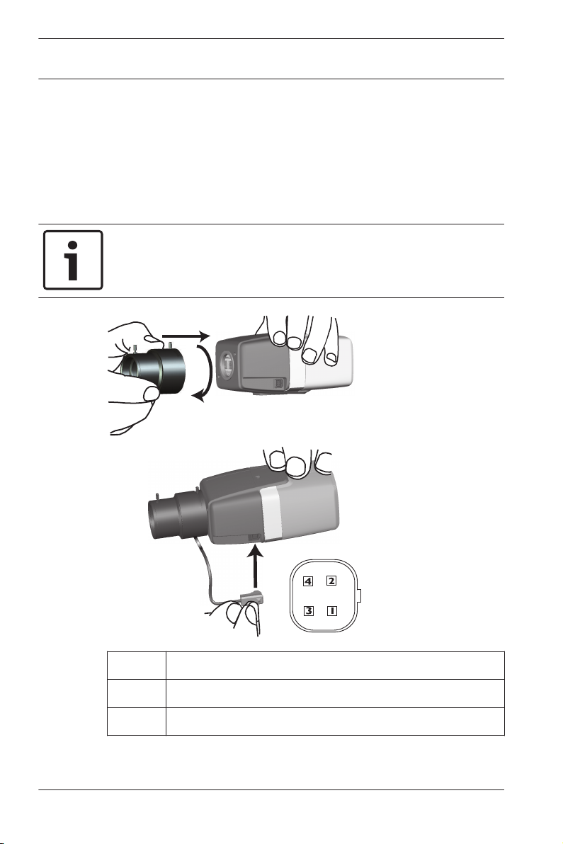
Lens mounting
This procedure is only required for cameras not having a factory
fitted lens.
Notice!
Lenses weighing more than 0.5 kg (1.1lbs) must be separately
supported.
Pin DC iris lens
1 Damp -
2 Damp +
2014.09 | v1.0 | AM18-Q0674 Bosch Security Systems
Page 15

DINION IP 7000 HD Installation | en 15
Pin DC iris lens
3 Drive +
4 Drive -
1. Remove the sensor protection cap from the camera (if
present).
2. Screw the lens onto the camera using the CS or C‑mount
(use the adapter ring to attach a C-mount lens).
3. Plug the lens connector into the camera (it automatically
detects the type of lens).
If a short circuit is detected on the lens connector, the lens
circuit is automatically disabled to avoid internal damage. In
this case, remove the lens connector and check the pin
connections.
Bosch Security Systems 2014.09 | v1.0 | AM18-Q0674
Page 16
1/4”-20 UNC
16 en | Installation DINION IP 7000 HD
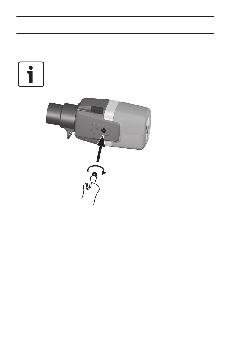
5.2
Mounting the camera
Notice!
Do not expose the image sensors to direct sunlight.
Do not obstruct the free flow of air around the camera.
The camera can be mounted either from the top or from the
bottom (1/4" 20 UNC thread).
2014.09 | v1.0 | AM18-Q0674 Bosch Security Systems
Page 17
4 5 6 4 5 6
1 2 3 1 2 3||
- +
MENU
CVBS
E
T
H
P
o
E
D
A
T
A
A
L
A
R
M
DINION IP 7000 HD Installation | en 17
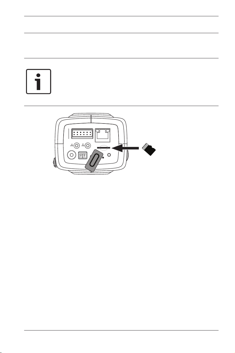
5.3
Local storage
Notice!
Local storage on SD cards should only be used for alarm
recording. To minimize the risk of losing information, use
multiple, redundant recording systems and a procedure to back
up all digital information.
1. Unscrew the card slot cover.
2. Slide the memory card into the slot until it locks in place.
3. Screw the cover into place to seal the slot.
Bosch Security Systems 2014.09 | v1.0 | AM18-Q0674
Page 18

4 5 6 4 5 6
1 2 3 1 2 3||
12VDC
- +
CVBS
24VAC
MENU
µSD
E
T
H
P
o
E
D
A
T
A
A
L
A
R
M
Ethernet (PoE)
STP Cat 5e
RJ45
Earth
!
18 en | Connection DINION IP 7000 HD
6
6.1
Connection
Network (and PoE power)
1. Connect the earth terminal of the camera to the system
earth of the installation to ensure correct safety and
EMC/RFI protection
2. Connect the camera to a 10/100 Base-T network:
– Use STP Category 5e cable with RJ45 connectors (the
camera network socket is Auto MDIX compliant).
– Power can be supplied to the camera via the Ethernet
cable compliant with the Power-over-Ethernet
standard.
The LEDs beside the Ethernet connection indicate Power (red),
IP connection (green) and IP traffic (green flashing).
Caution!
This device must be connected to earth (ground).
Safety (power) ground is indicated by the symbol.
2014.09 | v1.0 | AM18-Q0674 Bosch Security Systems
Page 19

DINION IP 7000 HD Connection | en 19
Notice!
Use only PoE approved devices.
Power-over-Ethernet can be connected at the same time as a
12 VDC or 24 VAC power supply. If auxiliary power (12 VDC or
24 VAC) and PoE is applied simultaneously, the camera selects
the auxiliary input and shuts off PoE.
Bosch Security Systems 2014.09 | v1.0 | AM18-Q0674
Page 20

!
!
5 mm
4 5 6 4 5 6
1 2 3 1 2 3||
12VDC
- +
CVBS
24VAC
MENU
µSD
E
T
H
P
o
E
D
A
T
A
A
L
A
R
M
Earth
20 en | Connection DINION IP 7000 HD
6.2
Auxiliary power
Caution!
Installation should only be performed by qualified service
personnel in accordance with the National Electrical Code
(NEC 800 CEC Section 60) or applicable local codes.
Caution!
The Low Voltage power supply unit must comply with EN/UL
60950. The power supply must be a SELV-LPS unit or a SELV -
Class 2 unit (Safety Extra Low Voltage - Limited Power Source).
Connect an approved power supply unit with a rated supply
voltage of 24 VAC or 12 VDC as follows:
1. Strip back 5 mm (0.2 in) of insulation on the power supply
cable (must be 16-22 AWG stranded wire or 16-26 AWG
solid wire).
2. Connect the earth terminal of the camera to the system
earth of the installation to ensure correct safety and
EMC/RFI protection.
2014.09 | v1.0 | AM18-Q0674 Bosch Security Systems
Page 21

DINION IP 7000 HD Connection | en 21
3. Loosen the screws of the supplied 2-pole connector and
insert the stripped wires, then tighten the screws again.
4. Insert the 2-pole connector into the camera power socket.
Bosch Security Systems 2014.09 | v1.0 | AM18-Q0674
Page 22

5 mm
(0.2 in)
4 5 6 4 5 6
1 2 3 1 2 3||
- +
CVBS
MENU
µSD
E
T
H
P
o
E
D
A
T
A
A L A R M
Alarm
4 5 6
1 2 3
|
|
22 en | Connection DINION IP 7000 HD
6.3
Alarm
Pin
1 Alarm in 1
2 Alarm in 2
3 Alarm out contact 1
4 Ground
Alarm socket
5 Ground
6 Alarm out contact 2
The maximum wire diameter is AWG 22-28 for both stranded
and solid; cut back 5 mm (0.2 in) of insulation.
Alarm out
2014.09 | v1.0 | AM18-Q0674 Bosch Security Systems
Use the alarm output for switching external devices such as
lamps or sirens.
Alarm output switching capability:
– Max. voltage 30 VAC or +40 VDC. Max. 0.5 A continuous,
10 VA.
Page 23

DINION IP 7000 HD Connection | en 23
Alarm in:
Use the alarm input to connect external alarm devices such as
door contacts or sensors:
– TTL logic, +5 V nominal, +40 VDC max, DC coupled with
50 kOhm pull-up to +3.3 V.
– Configurable as active low or active high.
A zero potential make-contact or switch can be used as the
actuator (use a bounce-free contact system).
Note:
If IR illumination is used, the alarm interface provides a stable
switching control of the day/night function of the camera.
Bosch Security Systems 2014.09 | v1.0 | AM18-Q0674
Page 24

4 5 6 4 5 6
1 2 3 1 2 3||
- +
MENU
CVBS
µSD
E
T
H
P
o
E
D
A
T
A
A
L
A
R
M
Line
GND
OutputInput
24 en | Connection DINION IP 7000 HD
6.4
Audio
Connect audio devices to the Audio In and Audio Out
connectors.
The unit has full-duplex mono audio for two-way communication
between a speaker or door intercom system. The audio input
signal is transmitted in sync. with the video signal.
Audio input: Line input level (not suitable for direct microphone
signal); impedance 18 kOhm typical; 1 Vrms maximum input
voltage.
Audio output: Line output level (not suitable for direct speaker
connection); impedance 1.5 kOhm minimum; 0.85 Vrms
maximum output voltage.
Wiring: Use shielded audio connection cable with advised
maximum cable lengths for audio line input and output levels.
2014.09 | v1.0 | AM18-Q0674 Bosch Security Systems
Page 25

4 5 6 4 5 6
1 2 3 1 2 3||
- +
MENU
CVBS
µSD
E
T
H
P
o
E
D
A
T
A
A
L
A
R
M
NBN-MCSMB
(optional)
DINION IP 7000 HD Connection | en 25
6.5
Video monitor
Use the composite video connector (CVBS) on the camera to
connect an analog monitor for setting up the camera or as a
permanent analog output for viewing or recording:
– To connect a monitor for set-up, use the optional 3 m cable
(NBN-MCSMB-30M) to connect directly to the CVBS
connector of a monitor.
– For a permanent analog output, use the optional 0.3 m
cable (NBN-MCSMB-03M) to connect to a high quality coax
cable.
Bosch Security Systems 2014.09 | v1.0 | AM18-Q0674
Page 26

5 mm
(0.2 in)
4 5 6 4 5 6
1 2 3 1 2 3||
- +
CVBS
MENU
µSD
E
T
H
P
o
E
D A T A
A
L
A
R
M
Data
4 5 6
1 2 3||
26 en | Connection DINION IP 7000 HD
6.6
Data
Pin
1 Ground
2 RxD / Rx+
3 Rx-
4 Ground
Data socket
5 TxD / Tx-
6 Tx+
Use the data connector to connect to an external device for
sending control data from the camera to the external device.
This data connection supports RS485, RS422, and RS232.
Note:
2014.09 | v1.0 | AM18-Q0674 Bosch Security Systems
To ensure surge and electrostatic protection, keep the cable
length between the camera and external device to less than 3
meters.
Page 27

4 5 6 4 5 6
1 2 3 1 2 3||
- +
MENU
CVBS
µSD
E
T
H
P
o
E
D
A
T
A
A
L
A
R
M
DINION IP 7000 HD Configuration | en 27
7
7.1
7.1.1
Configuration
Setting the field of view
When the camera is mounted and connected, its field of view
and focus point must be set. To do this:
1. Connect a monitor to the CVBS connector on the rear of
the camera.
2. Start the install wizard.
Camera install wizard
MENU button on the rear panel is used for accessing the
The
camera install wizard. The wizard fine-tunes the focus and
optimizes picture sharpness in both bright and low-level lighting
(for example, at night).
When there is a choice in the wizard, the options are selected by
either a short press or a longer press of the MENU button.
Select EXIT to close the wizard.
Notice!
Bosch Security Systems 2014.09 | v1.0 | AM18-Q0674
Changing the application variant overwrites your camera
settings with the factory defaults.
Page 28

Lens type: DC Iris State: Ready Focus indicator: 8
CONTINUE
< press short >
180° ROTATE
< press long >
Timeout: 300
Focus
(∞ <—> N)
Zoom
(T <—> W)
NBN-MCSMB
(optional)
28 en | Configuration DINION IP 7000 HD
7.1.2
Using the install wizard
1. Power-up the camera and wait briefly before opening the
camera install wizard.
2. Briefly press Menu to start the wizard and display the
following screen on the monitor:
The lens type is identified and shown on the screen.
The iris is opened to its maximum value.
3. To rotate the image 180°, press and hold Menu until the
image flips.
4. Briefly press Menu to continue.
5. Briefly press Menu to center the focus.
6. Manually adjust the focal length lever on the lens to obtain
the required field of view.
7. Manually adjust the focus lever on the lens to obtain the
sharpest image possible.
2014.09 | v1.0 | AM18-Q0674 Bosch Security Systems
Page 29

DINION IP 7000 HD Configuration | en 29
8. Briefly press Menu to start the automatic back focus
adjustment (AUTO BACK FOCUS).
– The motorized automatic back focus process runs.
– The progress is shown on the monitor.
9. If the camera is not in focus, press Menu for a longer time
to restart the wizard.
10. If the camera is correctly focused, briefly press the Menu
button to exit the wizard.
– The back focus position is stored.
– The iris is set to its original value.
Bosch Security Systems 2014.09 | v1.0 | AM18-Q0674
Page 30

30 en | Configuration DINION IP 7000 HD
7.2
True Day/Night switching
The camera is equipped with a motorized IR filter. This
mechanical IR filter is taken out of the optical path in low-light
conditions.
The IR filter is controlled either:
– via an alarm input, or
– automatically, based on the observed light levels.
If Auto switching mode is selected, the camera automatically
switches the filter depending on the observed light level. The
switching level is adjustable. (If the day to night switching level
is set to -15, certain borderline scene lighting conditions can
cause the camera to switch back and forth between day and
night modes. Set a different switching level to avoid this.)
Note:
If IR illumination is used, the alarm interface provides a stable
switching control for the day/night function of the camera.
2014.09 | v1.0 | AM18-Q0674 Bosch Security Systems
Page 31

DINION IP 7000 HD Configuration | en 31
7.3
7.3.1
Camera configuration
The camera normally provides an optimal picture without the
need for further adjustments. However, you can use a web
browser via the network to access a menu to change camera
settings such as user modes, passwords, picture settings and
network settings.
Configuration options using the menu system on the camera
itself are limited to basic setup via the Wizard.
Bosch Video Client
The Bosch Video Client is a free Windows application for
viewing, operating, controlling, and administering surveillance
cameras. It can be downloaded from:
http://downloadstore.boschsecurity.com/
The Configuration Manager, which is part of the Video Client, is
a useful tool for locating the IP addresses of cameras in your
network.
Refer to the Video Client Operator’s Manual for more
information.
Bosch Security Systems 2014.09 | v1.0 | AM18-Q0674
Page 32

32 en | Configuration DINION IP 7000 HD
7.4
7.4.1
7.4.2
Browser connection
A computer with Microsoft Internet Explorer is used to receive
live images, control the unit, and replay stored sequences. The
unit is configured over the network using the browser.
Establishing the connection
The unit must have a valid IP address to operate on your
network and a compatible subnet mask. By default, DHCP is preset at the factory to On and so your DHCP server assigns an IP
address. With no DHCP server the default address is
192.168.0.1
1. Start the Web browser.
2. Enter the IP address of the unit as the URL.
3. During initial installation, confirm any security questions
that appear.
Protected network
If a RADIUS server is used for network access control (802.1x
authentication), the unit must be configured first. To configure
the unit, connect it directly to a computer using a network cable
and configure the two parameters, Identity and Password. Only
after these have been configured can communication with the
unit via the network occur.
2014.09 | v1.0 | AM18-Q0674 Bosch Security Systems
Page 33

DINION IP 7000 HD Troubleshooting | en 33
8
8.1
8.2
Troubleshooting
Function test
The camera offers a variety of configuration options. Therefore,
check that it works properly after installation and configuration.
This is the only way to ensure that the camera will function as
intended in the event of an alarm.
Your check should include the following functions:
– Can you connect to the camera remotely
– Does the camera transmit all the data required?
– Does the camera respond as desired to alarm events?
– Is it possible to control peripheral devices, if necessary?
Resolving problems
The following table is intended to help identify the causes of
malfunctions and correct them where possible.
Malfunction Possible causes Solution
No image
transmission to
remote location.
Defective camera. Connect a local
monitor to the
camera and check
the camera function.
Faulty cable
connections.
Incorrect encoder
stream property set
for connection to
hardware decoder.
Bosch Security Systems 2014.09 | v1.0 | AM18-Q0674
Check all cables,
plugs, contacts and
connections.
Select the H.264 MP
SD option on the
Encoder Streams
configuration page.
Page 34

34 en | Troubleshooting DINION IP 7000 HD
Malfunction Possible causes Solution
No connection
established, no
image
transmission.
No audio
transmission to
remote station.
Incorrect unit
configuration.
Check all
configuration
parameters (reset to
factory default if
necessary).
Faulty installation. Check all cables,
plugs, contacts and
connections.
Wrong IP address. Check the IP
addresses (terminal
program).
Faulty data
transmission within
the LAN.
The maximum
number of
connections has
been reached.
Check the data
transmission with
ping.
Wait until there is a
free connection and
call the transmitter
again.
Hardware fault. Check that all
connected audio
units are operating
correctly.
Faulty cable
connections.
Check all cables,
plugs, contacts and
connections.
Incorrect
configuration.
Check audio
parameters on the
Audio configuration
and LIVE page
functions pages.
2014.09 | v1.0 | AM18-Q0674 Bosch Security Systems
Page 35

DINION IP 7000 HD Troubleshooting | en 35
Malfunction Possible causes Solution
The unit does
not report an
alarm.
Control of
cameras or other
units is not
possible.
The audio voice
connection is already
in use by another
receiver.
Alarm source is not
selected.
No alarm response
specified.
The cable connection
between the serial
interface and the
connected unit is not
correct.
Wait until the
connection is free
and then call the
sender again.
Select possible alarm
sources on the Alarm
sources configuration
page.
Specify the desired
alarm response on
the Alarm
connections
configuration page; if
necessary change the
IP address.
Check all cable
connections and
ensure all plugs are
properly fitted.
The unit is not
operational after
a firmware
upload.
The interface
parameters do not
match those of the
other unit connected.
Power failure during
programming by
firmware file.
Make sure that the
settings of all units
involved are
compatible.
Have the unit
checked by Customer
Service and replace if
necessary.
Bosch Security Systems 2014.09 | v1.0 | AM18-Q0674
Page 36

en | Troubleshooting DINION IP 7000 HD
36
Malfunction Possible causes Solution
Placeholder with
a red cross
instead of the
ActiveX
components.
Web browser
contains empty
fields.
The camera LED
flashes red.
Incorrect firmware
file.
JVM not installed on
your computer or not
activated.
Active proxy server in
network.
Firmware upload
failed.
Enter the IP address
of the unit followed
by /main.htmin your
Web browser and
repeat the upload.
Install JVM.
Create a rule in the
local computer's
proxy settings to
exclude local IP
addresses.
Repeat firmware
upload.
2014.09 | v1.0 | AM18-Q0674 Bosch Security Systems
Page 37

DINION IP 7000 HD Troubleshooting | en 37
8.3
8.4
Testing the network connection
The ping command can be used to check the connection
between two IP addresses. This allows testing whether a device
is active in the network.
1. Open the DOS command prompt.
2. Type ping followed by the IP address of the device.
If the device is found, the response appears as "Reply from ... ",
followed by the number of bytes sent and the transmission time
in milliseconds. Otherwise, the device cannot be accessed via
the network. This might be because:
– The device is not properly connected to the network. Check
the cable connections in this case.
– The device is not correctly integrated into the network.
Check the IP address, subnet mask, and gateway address.
Customer service
If a fault cannot be resolved, please contact your supplier or
system integrator, or go directly to Bosch Security Systems
Customer Service.
The version numbers of the internal firmware can be viewed on
a service page. Please note this information before contacting
Customer Service.
1. In the address bar of your browser, after the unit IP
address, enter: /version
for example: 192.168.0.80/version
2. Write down the information or print out the page.
Bosch Security Systems 2014.09 | v1.0 | AM18-Q0674
Page 38

38 en | Troubleshooting DINION IP 7000 HD
8.5
Terminal program
Data Terminal
If a camera cannot be found in the network or the connection to
the network is interrupted, you can connect a data terminal to
the camera for initial setup and for setting important
parameters. The data terminal consists of a computer with a
terminal program.
You require a serial transmission cable with a 9-pin Sub-D plug
to connect to the computer.
The communications accessory included with Windows can be
used as the terminal program.
1. Disconnect the camera from the Ethernet network before
working with the terminal program.
2. Connect the serial interface of the camera using any
available serial interface on the computer.
Configuring the Terminal
Before the terminal program can communicate with the camera,
the transmission parameters must be matched. Make the
following settings for the terminal program:
– 19,200 bps
– 8 data bits
– No parity check
– 1 stop bit
– No protocol
Command Inputs
After the connection has been established, you must log on to
the camera to access the main menu. Other submenus and
functions can be accessed using the on-screen commands.
1. If necessary, turn off the local echo so that entered values
are not repeated on the display.
2. Enter one command at a time.
3. When you have entered a value, such as the IP address,
check the characters you have entered before pressing
Enter to transfer the values to the camera.
2014.09 | v1.0 | AM18-Q0674 Bosch Security Systems
Page 39

DINION IP 7000 HD
Assigning an IP Address
Before you can operate a camera in your network you must first
assign it an IP address that is valid for your network.
The following default address is preset at the factory:
192.168.0.1
1. Start a terminal program such as HyperTerminal.
2. Enter the user name service. The terminal program displays
3. Enter command 1 to open the IP menu.
4. Enter 1 again. The terminal program displays the current IP
5. Enter the desired IP address and press Enter. The terminal
6. Use the displayed commands for any additional settings you
Note:
You must reboot to activate the new IP address, a new subnet
mask, or a gateway IP address.
Troubleshooting | en 39
the main menu.
address and prompts you to enter a new IP address.
program displays the new IP address.
require.
Reboot
Briefly interrupt the power supply to the camera for a reboot
(disconnect the power supply and switch on again after a few
seconds).
Additional Parameters
Use the terminal program to check other basic parameters and
modify them where necessary. Use the on-screen commands in
the various submenus to do this.
Bosch Security Systems 2014.09 | v1.0 | AM18-Q0674
Page 40

4 5 6 4 5 6
1 2 3 1 2 3||
- +
MENU
CVBS
µSD
E
T
H
P
o
E
D
A
T
A
A
L
A
R
M
40 en | Maintenance DINION IP 7000 HD
9
9.1
9.2
9.3
Maintenance
Cleaning
It is generally sufficient to use a dry cloth for cleaning, but a
moist lint-free cloth or leather shammy may also be used.
Do not use liquid cleaners or aerosol cleaners.
Repair
Notice!
Never open the casing of the unit
The unit does not contain any user-serviceable parts. Refer all
repairs to suitable qualified specialists.
Reset
Use the factory reset button to restore the unit to its original
settings. Any changes to the settings are overwritten by the
factory defaults. A reset may be necessary, for example, if the
unit has invalid settings that prevent it from functioning as
desired.
2014.09 | v1.0 | AM18-Q0674 Bosch Security Systems
Page 41

DINION IP 7000 HD Decommissioning | en 41
10
10.1
10.2
Decommissioning
Transfer
The camera should only be passed on together with this
installation guide.
Disposal
Disposal - Your Bosch product was developed and
manufactured with high-quality material and components that
can be recycled and reused. This symbol means that
electronic and electrical appliances, which have reached the
end of their working life, must be collected and disposed of
separately from household waste material. Separate collecting
systems are usually in place for disused electronic and
electrical products. Please dispose of these units at an
environmentally compatible recycling facility, per European
Directive 2012/19/EU.
Bosch Security Systems 2014.09 | v1.0 | AM18-Q0674
Page 42

42 en | Technical data DINION IP 7000 HD
11
11.1
Technical data
Specifications (NBN-71022)
Power
Power Supply 24 VAC 50/60 Hz
12 VDC
Power-over-Ethernet 48 VDC nominal
Current
Consumption
Power
Consumption
PoE IEEE 802.3af (802.3at Type 1)
Sensor
Type 1/2.7‑inch CMOS
Pixels 1952 x 1092 (2.03MP)
400 mA | 500 mA IVA (12 VDC)
350 mA | 450 mA IVA (24 VAC)
150 mA | 175 mA IVA (PoE 48 VDC)
4.8 W | 6 W IVA (12 VDC)
8.4 W | 10.8 W IVA (24 VAC)
7.2 W | 8.4 W IVA (PoE 48 VDC)
Video performance
Sensitivity – (3200K, reflectivity 89%, F1.2, 30IRE)
– Color 0.22 lx (0.022 fc)
– Mono 0.05 lx (0.005 fc)
Dynamic range 76 dB Wide Dynamic Range (92 dB with
iAE)
2014.09 | v1.0 | AM18-Q0674 Bosch Security Systems
Page 43

DINION IP 7000 HD Technical data | en 43
Video streaming
Video compression H.264 (MP); M-JPEG
Streaming Multiple configurable streams in H.264
and M-JPEG, configurable frame rate and
bandwidth.
Regions of Interest (ROI)
Overall IP Delay Min. 120 ms, Max. 240 ms
GOP structure IP, IBP, IBBP
Encoding interval 1 to 30 (25) ips
Resolutions (H x V)
– 1080p HD 1920 x 1080
– 960p HD 4:3
1280 x 960
(cropped)
– 720p HD 1280 x 720
– Upright 9:16
400 x 720
(cropped)
– D1 4:3
704 x 480
(cropped)
– 480p SD Encoding: 704 x 480;
Displayed: 854 x 480
– 432p SD 768 x 432
– 288p SD 512 x 288
– 240p SD Encoding: 352 x 240;
Displayed: 432 x 240
– 144p SD 256 x 144
Bosch Security Systems 2014.09 | v1.0 | AM18-Q0674
Page 44

en | Technical data DINION IP 7000 HD
44
Video functions
Day/Night Color, Mono, Auto
White Balance ATW (2500 to 10000K), ATWhold and
manual
Shutter Automatic Electronic Shutter (AES)
Fixed (1/30 [1/25] to 1/15000)
selectable
Default shutter
Backlight
Off, Auto
compensation
Contrast
On/off
enhancement
Sharpness Sharpness enhancement level selectable
Privacy Masking Four independent areas, fully
programmable
Video Motion
Motion+ or IVA option
Analysis
2014.09 | v1.0 | AM18-Q0674 Bosch Security Systems
Page 45

DINION IP 7000 HD Technical data | en 45
11.2
Specifications (NBN-71027)
Power
Power Supply 24 VAC 50/60 Hz
12 VDC
Power-over-Ethernet 48 VDC nominal
Current
Consumption
Power
Consumption
PoE IEEE 802.3af (802.3at Type 1)
Sensor
Type 1/3‑inch CMOS
Pixels 2048 x 1536 (3MP)
Video performance
500 mA (12 VDC)
450 mA (24 VAC)
175 mA (PoE 48 VDC)
6 W (12 VDC)
10.8 W (24 VAC)
8.4 W (PoE 48 VDC)
Sensitivity – (3200K, reflectivity 89%, F1.2, 30IRE)
– Color 0.25 lx (0.025 fc)
– Mono 0.08 lx (0.008 fc)
Dynamic range 90 dB High Dynamic Range (HDR)
106 dB HDR (with iAE)
Bosch Security Systems 2014.09 | v1.0 | AM18-Q0674
Page 46

46 en | Technical data DINION IP 7000 HD
Video streaming
Video compression H.264 (MP); M-JPEG
Streaming Multiple configurable streams in H.264
and M-JPEG, configurable frame rate and
bandwidth.
Regions of Interest (ROI)
Overall IP Delay Min. 120 ms, Max. 240 ms
GOP structure IP, IBP, IBBP
Encoding interval 1 to 30 (25) ips
Resolutions (H x V)
– 1080p HD 1920 x 1080
– 960p HD 4:3
1280 x 960
(cropped)
– 720p HD 1280 x 720
– Upright 9:16
400 x 720
(cropped)
– D1 4:3
704 x 480
(cropped)
– 480p SD Encoding: 704 x 480;
Displayed: 854 x 480
– 432p SD 768 x 432
– 288p SD 512 x 288
– 240p SD Encoding: 352 x 240;
Displayed: 432 x 240
– 144p SD 256 x 144
2014.09 | v1.0 | AM18-Q0674 Bosch Security Systems
Page 47

DINION IP 7000 HD
Video functions
Day/Night Color, Mono, Auto
White Balance ATW (2500 to 10000K), ATWhold and
Shutter Automatic Electronic Shutter (AES)
High dynamic range On/off
Technical data | en 47
manual
Fixed (1/30 [1/25] to 1/15000)
selectable
Default shutter
Backlight
Off / On / iAE
compensation
Contrast
On/off
enhancement
Noise reduction Intelligent Dynamic Noise Reduction
(iDNR) with separate temporal and
spatial adjustments
Sharpness Sharpness enhancement level selectable
Privacy Masking Four independent areas, fully
programmable
Video Motion
Intelligent Video Analysis (IVA)
Analysis
Bosch Security Systems 2014.09 | v1.0 | AM18-Q0674
Page 48

48 en | Technical data DINION IP 7000 HD
11.3
Specifications (NBN-71013)
Power
Power Supply 24 VAC 50/60 Hz
12 VDC
Power-over-Ethernet 48 VDC nominal
Current
Consumption
Power
Consumption
PoE IEEE 802.3af (802.3at Type 1)
Sensor
Type 1/3‑inch CMOS
Pixels 1312 x 1069 (1.4MP)
Video performance
400 mA | 500 mA IVA (12 VDC)
350 mA | 450 mA IVA (24 VAC)
150 mA | 175 mA IVA (PoE 48 VDC)
4.8 W | 6 W IVA (12 VDC)
8.4 W | 10.8 W IVA (24 VAC)
7.2 W | 8.4 W IVA (PoE 48 VDC)
Sensitivity – (3200K, reflectivity 89%, 1/60 sec shutter time,
F1.2, 30IRE)
– Color 0.017 lx (0.0017 fc)
– Mono 0.0057 lx (0.00057 fc)
Dynamic range 84 dB WDR
100 dB WDR (with iAE)
2014.09 | v1.0 | AM18-Q0674 Bosch Security Systems
Page 49

DINION IP 7000 HD Technical data | en 49
Video streaming
Video compression H.264 (MP); M-JPEG
Streaming Multiple configurable streams in H.264
and M-JPEG, configurable frame rate and
bandwidth.
Regions of Interest (ROI)
Overall IP Delay Min. 120 ms, Max. 240 ms
GOP structure IP, IBP, IBBP
Encoding interval 1 to 60 (50) ips
Resolutions (H x V)
– 720p HD 1280 x 720
– 1024p 5:4
1280 x 1024 (30p max., no IVA)
(cropped)
– Upright 9:16
400 x 720
(cropped)
– D1 4:3
704 x 480
(cropped)
– 480p SD Encoding: 704 x 480;
Displayed: 854 x 480
– 432p SD 768 x 432
– 288p SD 512 x 288
– 240p SD Encoding: 352 x 240;
Displayed: 432 x 240
– 144p SD 256 x 144
Bosch Security Systems 2014.09 | v1.0 | AM18-Q0674
Page 50

en | Technical data DINION IP 7000 HD
50
Video functions
Day/Night Color, Mono, Auto
White Balance ATW (2500 to 10000K), ATWhold and
manual
Shutter Automatic Electronic Shutter (AES)
Fixed (1/30 [1/25] to 1/15000)
selectable
Default shutter
Backlight
Off / On / iAE (BLC)
compensation
Contrast
On/off
enhancement
Noise reduction Intelligent Dynamic Noise Reduction
(iDNR) with separate temporal and
spatial adjustments
Sharpness Sharpness enhancement level selectable
Privacy Masking Four independent areas, fully
programmable
Video Motion
Intelligent Video Analysis (IVA)
Analysis
2014.09 | v1.0 | AM18-Q0674 Bosch Security Systems
Page 51

DINION IP 7000 HD Technical data | en 51
11.4
Common specifications
Audio streaming
Audio Streaming Full duplex / half duplex
Signal-to-noise ratio > 50 dB
Audio compression AAC-LC, G.711, L16 (live and recording)
Input/output
Analog video out CVBS (PAL/NTSC), 1 Vpp, SMB, 75 Ohm
(surge protected)
Analog video aspect
ratio
Audio 1 x mono line in, 1 x mono line out
– connector 3.5 mm stereo jack
– signal line in 12 kOhm typical, 1 Vrms max
– signal line out 1 Vrms at 1.5 kOhm typical,
Alarm 2 inputs
4:3 letterbox, 4:3 cropped, or 16:9 mode
– connector Clamp (non-isolated closing contact)
– activation
voltage
Relay 1 output
– connector Clamp
– voltage 30 VAC or +40 VDC
Data port RS‑232/422/485
Bosch Security Systems 2014.09 | v1.0 | AM18-Q0674
+5 VDC to +40 VDC
(+3.3 VDC with DC-coupled 22 kOhm
pull-up resistor)
Maximum 0.5 A continuous, 10VA
Page 52

52 en | Technical data DINION IP 7000 HD
Local storage
Internal RAM 10 s pre-alarm recording
Memory card slot Supports up to 32 GB SDHC / 2 TB SDXC
card. (An SD card of Class 6 or higher is
recommended for HD recording)
Recording Continuous recording, ring recording.
alarm/events/schedule recording
Network
Protocols IPv4, IPv6, UDP, TCP, HTTP, HTTPS, RTP/
RTCP, IGMP V2/V3, ICMP, ICMPv6, RTSP,
FTP, Telnet, ARP, DHCP, NTP (SNTP),
SNMP (V1, MIB-II), 802.1x, DNS, DNSv6,
DDNS (DynDNS.org, selfHOST.de, noip.com), SMTP, iSCSI, UPnP (SSDP),
DiffServ (QoS), LLDP, SOAP, Dropbox,
CHAP, digest authentication
Encryption TLS 1.0, SSL, DES, 3DES, AES (optional)
Ethernet 10/100 Base-T, auto-sensing, half/full
duplex
Connectivity ONVIF Profile S, Auto-MDIX
Software
Unit Configuration Via web browser or Configuration
Manager
Firmware update Remotely programmable
Software viewer Web browser, Bosch Video Client, or
third party software
2014.09 | v1.0 | AM18-Q0674 Bosch Security Systems
Page 53

DINION IP 7000 HD Technical data | en 53
Optical
Lens mount CS mount (C-mount with adapter ring)
Lens connector Standard 4-pin DC-iris connector
Lens Types Manual and DC-Iris auto-detect with
override
DC-iris drive: max. 50 mA continuous
Lens Controls Wizard from web page or camera button
Mechanical
Dimensions
(W x H x L)
78 x 66 x140 mm (3.07 x 2.6 x 5.52 inch)
without lens
Weight 690 g (1.52 lb) without lens
Color RAL 9007 Metallic Titanium
Tripod Mount Bottom (isolated) and top 1/4-inch
20 UNC
Environmental
Operating
-20°C to +55°C (-4°F to 131°F)
Temperature
Operating
-20°C to +50°C (-4°F to 122°F)
Temperature (IVA)
Storage
-30°C to +70°C (-22°F to +158°F)
Temperature
Operating Humidity 20% to 93% RH
Storage Humidity up to 98% RH
Bosch Security Systems 2014.09 | v1.0 | AM18-Q0674
Page 54

Page 55

Page 56

Bosch Security Systems B.V.
Torenallee 49
5617 BA Eindhoven
The Netherlands
www.boschsecurity.com
© Bosch Security Systems B.V., 2014
 Loading...