

Bosch Video Management System
MBV-BPRO-45
en Configuration Manual


Table of contents
1
Using the Help 12
1.1 Finding information 12
1.2 Printing the Help 13
2
Introduction 14
3
System overview 17
3.1 Hardware requirements 17
3.2 Software requirements 18
3.3 License requirements 18
3.4 Supported system structures 18
4
Concepts 20
4.1 Configuration Wizard 20
4.2 Enterprise System 20
4.2.1 Scenarios 20
4.2.2 Permissions 23
4.2.3 Types of user groups 24
4.2.4 Licensing 24
4.3 Server Lookup 24
4.4 Remote access 25
4.5 iSCSI storage pool 28
4.6 Alarm handling 28
4.7 DVR devices 30
4.8 Mobile Video Service 30
5
Supported hardware 32
5.1 Installing hardware 33
5.2 Connecting a Bosch IntuiKey keyboard to Bosch VMS 33
5.2.1 Scenarios for Bosch IntuiKey keyboard connections 33
5.2.2 Connecting a Bosch IntuiKey keyboard to a decoder 35
5.2.3 Updating Bosch IntuiKey keyboard firmware 36
5.3 Connecting Bosch Allegiant Matrix to Bosch Video Management System 37
5.3.1 Bosch Allegiant Connection Overview 37
5.3.2 Configuring the control channel 39
5.3.3 Bosch Allegiant Satellite System Concept 40
5.3.4 Allegiant CCL commands supported in Bosch VMS 41
6
Getting started 44
6.1 Installing the software modules 44
6.2 Using Configuration Wizard 44
6.3 Accessing the system 54
6.4 Using Server Lookup 54
6.5 Configuring remote access 54
6.5.1 Configuring without Enterprise System 54
6.5.2 Configuring with Enterprise System 55
6.6 Activating the software licenses 55
6.7 Starting Configuration Client 56
6.8 Configuring the language of Configuration Client 56
6.9 Configuring the language of Operator Client 56
6.10 Adding a new license 57
6.11 Working offline 57
Bosch Video Management System Table of Contents | en 3
Bosch Sicherheitssysteme GmbH Configuration Manual 2013.03 | V1 | Configuration Client

7
Configuring devices 58
7.1 Configuring the Server List for Enterprise System 58
7.2 Configuring Server Lookup 59
7.3 Detecting NVRs, their recorded encoders, and decoders 60
7.4 Detecting VRM devices 61
7.5 Configuring NVRs 61
7.5.1 Configuring a Primary NVR 62
7.5.2 Switching an NVR to a Failover NVR 62
7.5.3 Switching an NVR to a Redundant NVR 63
7.5.4 Configuring a Failover NVR 63
7.5.5 Configuring a Redundant NVR 63
7.5.6 Assigning NVRs to Failover NVRs 64
7.5.7 Assigning NVRs to a Redundant NVR 64
7.5.8 Displaying information on an NVR 64
7.5.9 Changing the network address of an NVR / Failover NVR / Redundant NVR 65
7.6 Adding a device 65
7.7 Configuring an encoder / decoder 68
7.8 Configuring a decoder for use with a Bosch IntuiKey keyboard 69
7.9 Configuring multiple encoders / decoders 69
7.10 Configuring the integration of a DiBos system 70
7.11 Configuring the integration of a DVR 70
7.12 Configuring a Bosch Allegiant device 71
7.13 Configuring a startup Command Script 71
7.14 Changing the network address of a workstation 72
7.15 Enabling Forensic Search on a workstation 72
7.16 Assigning an analog monitor group to a workstation 72
7.17 Configuring an analog monitor group 72
7.18 Adding a monitor wall 73
7.19 Configuring a communication device 73
7.20 Configuring a peripheral device 74
7.21 Configuring network monitoring 74
7.22 Configuring a Bosch IntuiKey keyboard (workstation) 74
7.23 Configuring a Bosch IntuiKey keyboard (decoder) 74
7.24 Configuring an I/O module 75
7.25 Configuring an Allegiant CCL emulation 75
7.26 Adding a Mobile Video Service 75
7.27 Adding a VRM device with iSCSI storage 76
7.28 Configuring an iSCSI device 76
7.29 Adding a DSA E-Series iSCSI device 77
7.30 Adding a LUN 78
7.31 Formatting a LUN 78
7.32 Adding a Video Streaming Gateway device 79
7.33 Adding a Bosch camera to a VSG 79
7.34 Adding an ONVIF camera to a VSG 79
7.35 Configuring multicast for VSG 80
7.36 Switching on VSG recording 80
7.37 Adding a local storage or live only device 81
8
Configuring the structure 82
8.1 Configuring the Logical Tree 82
4 en | Table of Contents Bosch Video Management System
2013.03 | V1 | Configuration Client Configuration Manual Bosch Sicherheitssysteme GmbH

8.2 Adding a device to the Logical Tree 82
8.3 Removing a tree item 82
8.4 Managing resource files 83
8.5 Adding a Command Script 84
8.6 Managing pre-configured camera sequences 84
8.7 Adding a camera sequence 85
8.8 Adding a folder 86
8.9 Adding a map 86
8.10 Adding a link to another map 86
8.11 Assigning a map to a folder 87
8.12 Managing devices on a map 87
8.13 Adding a document 88
9
Configuring schedules 89
9.1 Configuring a Recording Schedule 89
9.2 Adding a Task Schedule 90
9.3 Configuring a standard Task Schedule 90
9.4 Configuring a recurring Task Schedule 90
9.5 Removing a Task Schedule 91
9.6 Adding holidays and exception days 91
9.7 Removing holidays and exception days 92
9.8 Renaming a schedule 92
10
Configuring cameras and recording settings 93
10.1 Copying and pasting in tables 93
10.2 Configuring stream quality settings 94
10.3 Configuring camera properties 94
10.4 Configuring recording settings (only VRM and Local Storage) 95
10.5 Configuring recording settings (only NVR) 95
10.6 Configuring PTZ port settings 97
10.7 Configuring PTZ camera settings 97
11
Configuring events and alarms 98
11.1 Copying and pasting in tables 99
11.2 Removing a table row 99
11.3 Managing resource files 99
11.4 Configuring an event 99
11.5 Duplicating an event 100
11.6 Logging user events 100
11.7 Configuring user event buttons 100
11.8 Creating a Compound Event 101
11.9 Editing a Compound Event 102
11.10 Configuring an alarm 102
11.11 Configuring settings for all alarms 103
12
Configuring Command Scripts 104
12.1 Managing Command Scripts 104
12.2 Configuring a Command Script to be started automatically 105
12.3 Importing a Command Script 105
12.4 Exporting a Command Script 105
12.5 Configuring a startup Command Script 105
13
Configuring users, permissions and Enterprise Access 107
13.1 Creating a user 107
Bosch Video Management System Table of Contents | en 5
Bosch Sicherheitssysteme GmbH Configuration Manual 2013.03 | V1 | Configuration Client

13.2 Creating a group or account 108
13.3 Creating a dual authorization group 109
13.4 Configuring LDAP settings 109
13.5 Associating an LDAP group 110
13.6 Scheduling user logon permission 110
13.7 Configuring operating permissions 111
13.8 Configuring user interface settings 111
13.9 Configuring permissions for Logical Tree 112
13.10 Configuring permissions for events and alarms 112
13.11 Configuring camera permissions 113
13.12 Configuring decoder permissions 113
13.13 Configuring various priorities 113
13.14 Copying user group permissions 114
14
Managing configuration data 116
14.1 Activating the working configuration 116
14.2 Activating a configuration 117
14.3 Exporting configuration data 117
14.4 Importing configuration data 117
14.5 Exporting configuration data to OPC 118
15
Configuration examples 119
15.1 Creating an Enterprise System 119
15.1.1 Configuring the Server List for Enterprise System 119
15.1.2 Creating an Enterprise User Group 120
15.1.3 Creating an Enterprise Account 121
15.2 Adding a Bosch ATM/POS bridge 122
15.3 Adding a Bosch Allegiant input alarm 123
15.4 Adding and configuring 2 Dinion IP cameras with VRM recording 124
16
Global Configuration Client windows 126
16.1 Configuration window 126
16.2 Menu commands 127
16.3 Activation Manager dialog box 128
16.4 Activate Configuration dialog box 129
16.5 License Manager dialog box 129
16.6 License Activation dialog box 129
16.7 Alarm Settings dialog box 130
16.8 Stream Quality Settings dialog box 130
16.9 Options dialog box 131
16.10 Remote Access Settings dialog box 132
16.10.1 Show Port Mapping dialog box 132
17
Devices page 134
17.1 Server List page 135
17.1.1 Add Server dialog box 135
17.2 Initial Device Scan dialog box 135
17.3 NVR & Decoder Scan dialog box 136
17.4 Bosch VMS Scan Wizard 136
17.5 Failover NVR Manager dialog box 137
17.6 IP Device Configuration dialog box 137
17.7 Set IP Addresses dialog box 138
17.8 Set Display Names dialog box 138
6 en | Table of Contents Bosch Video Management System
2013.03 | V1 | Configuration Client Configuration Manual Bosch Sicherheitssysteme GmbH

17.9 NVRs / Failover NVRs / Redundant NVRs page 138
17.9.1 Global Settings page 139
17.9.2 Disk Storage page 139
17.9.3 Camera Storage page 140
17.9.4 Assigned NVRs page 141
17.9.5 Assigned NVR page 141
17.9.6 Add Network Path dialog box 142
17.9.7 Add Local NVR Drive dialog box 142
17.10 Vidos NVRs page 142
17.11 DiBos page 143
17.11.1 Add DiBos System dialog box 143
17.11.2 Settings page 143
17.11.3 Cameras page 143
17.11.4 Inputs page 143
17.11.5 Relays page 144
17.12 DVR (Digital Video Recorder) page 144
17.12.1 Add DVR dialog box 144
17.12.2 Settings tab 144
17.12.3 Cameras tab 145
17.12.4 Inputs tab 145
17.12.5 Relays tab 145
17.13 Matrix Switches page 145
17.13.1 Connection page 145
17.13.2 Cameras page 145
17.13.3 Outputs page 146
17.13.4 Inputs page 146
17.14 Workstation page 147
17.14.1 Settings page 147
17.14.2 Assigned Analog Monitor Groups page 148
17.15 Decoders page 148
17.16 Analog Monitor Groups page 148
17.16.1 Settings page 149
17.16.2 Advanced Configuration page 149
17.17 Monitor Wall page 150
17.17.1 Add Monitor Wall dialog box 151
17.18 Communication Devices page 151
17.18.1 E-mail/SMTP Server dialog box 151
17.18.2 Add SMS Device dialog box 151
17.18.3 SMTP Server page 152
17.18.4 Send Test E-mail dialog box 152
17.18.5 GSM Settings / SMSC Settings page 153
17.19 POS + ATM page 153
17.19.1 Add Bosch ATM/POS-Bridge dialog box 154
17.19.2 Bosch ATM/POS-Bridge page 154
17.19.3 Inputs page 154
17.19.4 ATM Settings page 154
17.20 Virtual Inputs page 155
17.20.1 Add Virtual Inputs dialog box 155
17.21 SNMP page 155
17.21.1 Add SNMP dialog box 155
Bosch Video Management System Table of Contents | en 7
Bosch Sicherheitssysteme GmbH Configuration Manual 2013.03 | V1 | Configuration Client

17.21.2 SNMP Trap Receiver page 156
17.21.3 SNMP Trap Logger dialog box 156
17.22 Assign Keyboard page 157
17.23 I/O Modules page 157
17.23.1 ADAM page 158
17.23.2 Inputs page 158
17.23.3 Relays page 158
17.24 Allegiant CCL Emulation page 158
17.25 Mobile Video Service page 159
17.25.1 Add Mobile Video Service dialog box 159
17.26 VRM Devices page 160
17.27 VRM Settings page 160
17.27.1 SNMP page 161
17.27.2 Advanced page 161
17.28 Pool page 161
17.28.1 Basic Configuration page 162
17.28.2 Load Balancing page 164
17.28.3 iqn-Mapper dialog box 164
17.28.4 LUNs page 164
17.28.5 Add LUN dialog box 165
17.29 Add DSA E-Series Device dialog box 165
17.30 Video Streaming Gateway device page 166
17.31 Assignment tab (Video Streaming Gateway) 166
17.32 Add/Edit dialog box (Video Streaming Gateway) 166
17.33 Recording profiles tab (Video Streaming Gateway) 168
17.34 Multicast tabs (Video Streaming Gateway) 168
17.35 Advanced tab (Video Streaming Gateway) 169
17.36 Live Only page 169
17.36.1 ONVIF Encoder page 169
17.36.2 Add ONVIF dialog box 170
17.37 Local Storage page 170
18
Encoders / Decoders page 171
18.1 Unit Access page 171
18.1.1 Identification / Camera identification 171
18.1.2 Camera name 172
18.1.3 Version information 172
18.2 Date/Time page 172
18.3 Video Input page 172
18.3.1 Picture settings 174
18.3.2 Input termination 174
18.3.3 Source type 175
18.4 Installer Menu 175
18.4.1 Base frame rate 175
18.4.2 Camera LED 175
18.4.3 Mirror image 175
18.4.4 Flip image 175
18.4.5 Menu button 175
18.4.6 Heater (dome cameras only) 175
18.4.7 Reboot device 175
8 en | Table of Contents Bosch Video Management System
2013.03 | V1 | Configuration Client Configuration Manual Bosch Sicherheitssysteme GmbH

18.4.8 Factory defaults 175
18.4.9 Lens Wizard 175
18.5 Picture Settings 175
18.5.1 White balance 176
18.6 Recording Management page 176
18.7 Recording preferences page 177
18.8 VCA page 177
18.8.1 Motion detector (MOTION+ only) 178
18.8.2 Select Area dialog box 179
18.8.3 Tamper detection 179
18.9 Audio Alarm page 180
18.10 Privacy Masks page 180
18.11 Camera page 181
18.11.1 Mode page 182
18.11.2 ALC 183
18.11.3 Enhance 184
18.12 Lens page 184
18.12.1 Focus 184
18.12.2 Iris 185
18.12.3 Zoom 185
18.13 PTZ page 186
18.14 Prepositions and Tours page 186
18.15 Sectors page 187
18.16 Misc page 187
18.17 Logs page 187
18.18 Audio page 187
18.19 Relay page 188
18.20 Periphery page 189
18.20.1 COM1 189
18.21 Network Access page 189
18.22 Advanced page 191
18.22.1 SNMP 191
18.22.2 802.1x 191
18.22.3 RTSP 191
18.22.4 UPnP 191
18.22.5 TCP metadata input 191
18.22.6 Quality of Service 192
18.23 Multicast page 192
18.24 FTP Posting page 193
18.24.1 JPEG posting 193
18.24.2 FTP server 193
18.25 IP v4 Filter 193
18.26 Licenses page 194
18.27 Decoder page 194
18.27.1 Decoder profile 194
18.27.2 Monitor display 194
19
Maps and Structure page 196
19.1 Resource Manager dialog box 197
19.2 Select Resource dialog box 197
Bosch Video Management System Table of Contents | en 9
Bosch Sicherheitssysteme GmbH Configuration Manual 2013.03 | V1 | Configuration Client

19.3 Sequence Builder dialog box 198
19.4 Add Sequence dialog box 198
19.5 Add Sequence Step dialog box 199
19.6 Add URL dialog box 199
19.7 Select Map for Link dialog box 199
20
Schedules page 200
20.1 Recording Schedules page 200
20.2 Task Schedules page 200
21
Cameras and Recording page 202
21.1 Cameras page 202
21.2 Scheduled Recording Settings dialog box (only VRM and Local Storage) 204
21.3 Recording settings pages (NVR only) 205
21.4 Stream Quality Settings dialog box 206
21.5 PTZ Settings dialog box 208
22
Events page 209
22.1 Command Script Editor dialog box 210
22.2 Create Compound Event / Edit Compound Event dialog box 211
22.3 Select Script Language dialog box 211
22.4 Edit Priorities of Event Type dialog box 212
22.5 Select Devices dialog box 212
23
Alarms page 213
23.1 Alarm Settings dialog box 214
23.2 Select Image Pane Content dialog box 214
23.3 Select Resource dialog box 215
23.4 Alarm Options dialog box 215
24
User Groups page 218
24.1 New User Group/Account dialog box 219
24.2 User Group Properties page 220
24.3 User Properties page 221
24.4 Add New Dual Authorization Group dialog box 221
24.5 Logon Pair Properties page 222
24.6 Select User Groups dialog box 222
24.7 Camera Permissions page 223
24.8 Control Priorities 224
24.9 Copy User Group Permissions dialog box 224
24.10 Decoder Permissions page 225
24.11 Events and Alarms page 225
24.12 LDAP Server Settings dialog box 226
24.13 Credentials page 228
24.14 Logical Tree page 228
24.15 Operator Features page 228
24.16 Priorities page 230
24.17 User Interface page 231
24.18 Server Access page 231
25
Troubleshooting 233
25.1 Configuring the desired language in Windows 235
25.2 Reestablishing the connection to a Bosch IntuiKey keyboard 235
25.3 Reducing the number of Allegiant cameras 235
10 en | Table of Contents Bosch Video Management System
2013.03 | V1 | Configuration Client Configuration Manual Bosch Sicherheitssysteme GmbH

Glossary 236
Index 243
Bosch Video Management System Table of Contents | en 11
Bosch Sicherheitssysteme GmbH Configuration Manual 2013.03 | V1 | Configuration Client

Using the Help
To find out more about how to do something in Bosch VMS, access the online Help using any
of the following methods.
To use the Contents, Index, or Search:
4
On the Help menu, click Help. Use the buttons and links to navigate.
To get Help on a window or dialog:
4
On the toolbar, click .
OR
4
Press F1 for help on any program window or dialog.
Finding information
You can find information in the Help in several ways.
To find information in the Online Help:
1. On the Help menu, click Help.
2. If the left-hand pane is not visible, click the Show button.
3. In the Help window, do the following:
Click: To:
Contents Display the table of contents for the Online Help. Click each book to
display pages that link to topics, and click each page to display the
corresponding topic in the right-hand pane.
Index Search for specific words or phrases or select from a list of index
keywords. Double-click the keyword to display the corresponding topic
in the right-hand pane.
Search Locate words or phrases within the content of your topics. Type the
word or phrase in the text field, press ENTER, and select the topic you
want from the list of topics.
Texts of the user interface are marked bold.
4
The arrow invites you to click on the underlined text or to click an item in the application.
4
Click to get step-by-step instructions
Related Topics
4
Click to display a topic with information on the application window you currently use.
This topic provides information on the application window controls.
Concepts provides background information on selected issues.
Caution!
Medium risk (without safety alert symbol): Indicates a potentially hazardous situation.
If not avoided, this may result in property damage or risk of damage to the unit.
Cautionary messages should be heeded to help you avoid data loss or damaging the system.
i
Notice!
This symbol indicates information or a company policy that relates directly or indirectly to the
safety of personnel or protection of property.
1
1.1
12 en | Using the Help Bosch Video Management System
2013.03 | V1 | Configuration Client Configuration Manual Bosch Sicherheitssysteme GmbH

Printing the Help
While using the Online Help, you can print topics and information right from the browser
window.
To print a Help topic:
1. Right-click in the right pane and select Print.
The Print dialog box opens.
2. Click Print. The topic is printed to the specified printer.
1.2
Bosch Video Management System Using the Help | en 13
Bosch Sicherheitssysteme GmbH Configuration Manual 2013.03 | V1 | Configuration Client
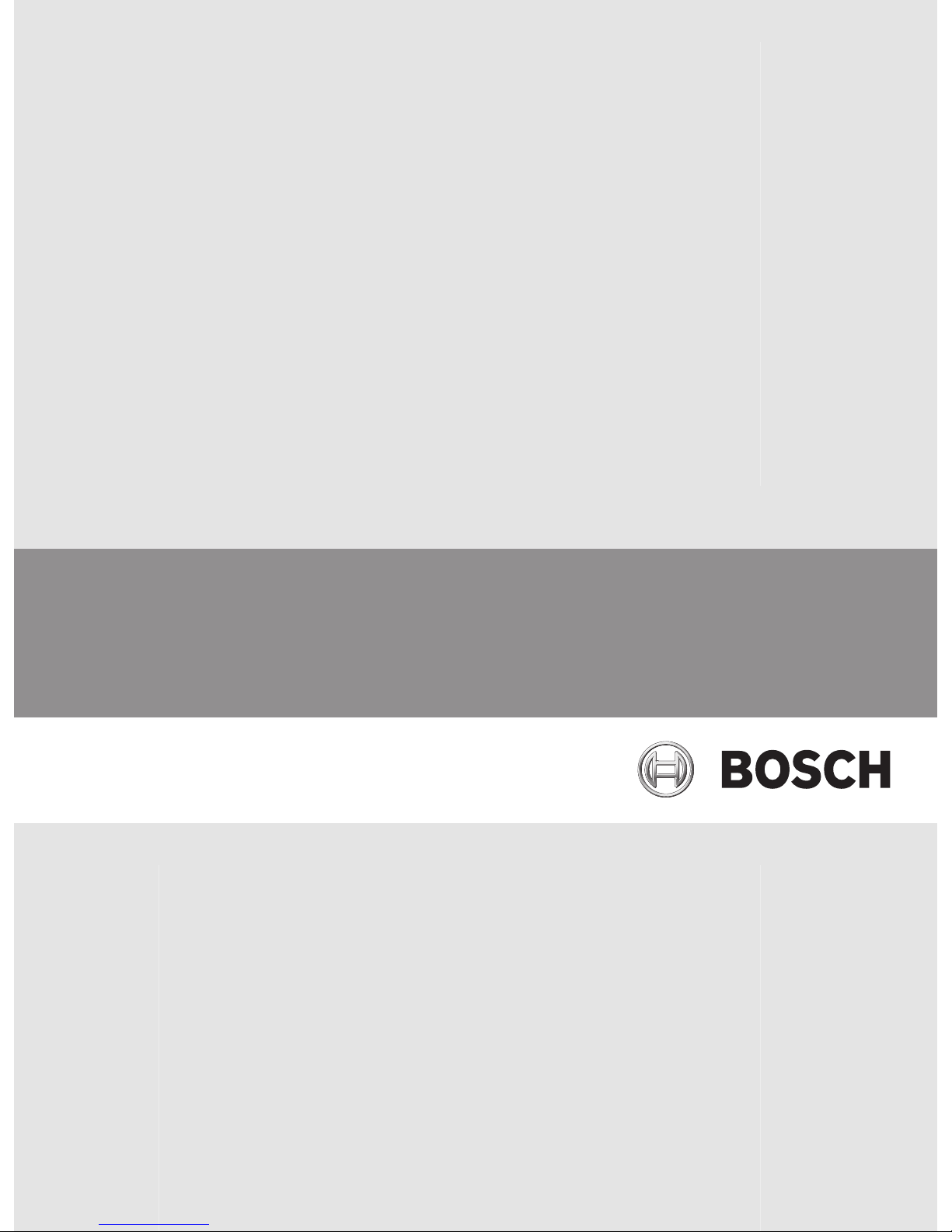
Introduction
1 Menu bar Allows you to select a menu command.
2 Toolbar Displays the available buttons. Point to an icon to
display a tooltip.
3 Playback controls Allows you to control instant playback or a camera
sequence or alarm sequence.
4 Performance meter Displays the CPU usage and the memory usage.
5 Time zone selector Select an entry for the time zone to be displayed in
most time related fields.
Only available if at least one Management Server in
the Logical Tree is located in another time zone as
your Operator Client.
6 Slider for Image pane pattern Allows you to select the required number of Image
panes.
7 Image window Displays the Image panes. Allows you to arrange the
Image panes.
2
14 en | Introduction Bosch Video Management System
2013.03 | V1 | Configuration Client Configuration Manual Bosch Sicherheitssysteme GmbH
8 Image pane Displays a camera, a map, an image, a document
(HTML file).
9
Alarm List window
Displays all alarms that the system generates.
Allows you to accept or clear an alarm or to start a
workflow, for example, by sending an E-mail to a
maintenance person.
The Alarm List is not being displayed, when the
connection to the Management Server is lost.
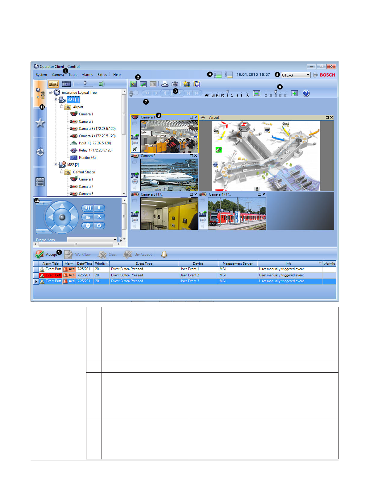
10
Monitors window
(only available if at least one
analog monitor group has been
configured)
Displays the configured analog monitor groups.
Allows you to switch to the next or previous analog
monitor group if available.
Note:
The Monitors tab is not visible if your Operator Client
is connected to more than one Management Server.
PTZ Control window
Allows you to control a PTZ camera.
11
Logical Tree window
Displays the devices your user group has access to.
Allows you to select a device for assigning it to an
Image pane.
Favorites Tree
window
Allows you to organize the devices of the Logical Tree
as required.
Bookmarks window
Allows to manage bookmarks.
Map window
Displays a site map. Allows you to drag the map to
display a particular section of the map.
If activated, a map is displayed automatically for each
camera displayed in an Image pane. In this case, the
camera must be configured on a map.
This manual guides you through the basic steps of the configuration and operation with Bosch
VMS.
For detailed help and step-by-step instructions read the Configuration Manual and the
Operator’s Manual or use the Online Help. You find the manuals as PDF files on your
Setup CD.
Bosch VMS integrates digital video, audio and data across any IP network.
The system consists of the following software modules:
– Management Server
– VRM recording (Video Recording Manager)
– Operator Client (VRM recording / DiBos DVRs / iSCSI recording / VIDOS NVRs / local
recording)
– Configuration Client
Bosch Video Management System
Introduction | en 15
Bosch Sicherheitssysteme GmbH Configuration Manual 2013.03 | V1 | Configuration Client

To achieve a running system, you must perform the following tasks:
– Install services (Management Server and VRM)
– Install Operator Client and Configuration Client
– Connect to network
– Connect devices to network
– Basic configuration:
– Add devices (e.g. by device scan)
– Build logical structure
– Configure schedules, cameras, events, and alarms
– Configure user groups
Bosch VMS Archive Player displays exported recordings.
16 en | Introduction Bosch Video Management System
2013.03 | V1 | Configuration Client Configuration Manual Bosch Sicherheitssysteme GmbH

System overview
If you plan to install and configure Bosch VMS, participate in a system training on Bosch VMS.
Refer to the Release Notes of the current Bosch VMS version for supported versions of
firmware and hardware and other important information.
See data sheets on Bosch workstations and servers for information on computers where
Bosch VMS can be installed.
The Bosch VMS software modules can optionally be installed on one PC.
Important components
– Management Server (selectable in Setup): Stream management, alarm management,
priority management, Management logbook, user management, device state management.
Additional Enterprise System license: Managing Enterprise User Groups and Enterprise
Accounts.
– Configuration Wizard: Easy and fast setup of a recording system.
– Configuration Client (selectable in Setup): System configuration and administration for
Operator Client.
– Operator Client (selectable in Setup): Live monitoring, storage retrieval and playback,
alarm and accessing multiple Management Server computers simultaneously.
– Video Recording Manager (selectable in Setup): Distributing storage capacities on iSCSI
devices to the encoders, while handling load balancing between multiple iSCSI devices.
Streaming playback video and audio data from iSCSI to Operator Clients.
– Mobile Video Service (selectable in Setup): Provides a transcoding service that
transcodes the live and recorded video stream from a camera configured in Bosch VMS to
the available network bandwidth. This service enables video clients like an iPhone or a
Web client to receive transcoded streams, for example for unreliable network
connections with limited bandwidth. Not supported on Windows XP.
– Web Client: You can access live and playback videos via Web browser.
– Mobile App: You can use the Mobile App on iPhone or iPad to access live and playback
video.
– Bosch Video Streaming Gateway (selectable in Setup): Provides the integration of 3rd
party cameras and NVR-like recording, e.g. in low-bandwidth networks.
– Cameo SDK (selectable in Setup): The Cameo SDK is used to embed Bosch VMS live and
playback Image panes to your external third-party application. The Image panes follow the
Bosch VMS based user permissions.
The Cameo SDK provides a subset of the Bosch VMS Operator Client functionalities that
enables you to create applications similar to the Operator Client.
– Client Enterprise SDK: The Client Enterprise SDK is meant to control and monitor the
behaviour of Operator Client of an Enterprise System by external applications. The SDK
allows to browse devices that are accessible by the running, connected Operator Client
and to control some UI functionalities.
– Client SDK / Server SDK: The Server SDK is used to control and monitor the Management
Server by scripts and external applications. You can use those interfaces with a valid
administrator account.
The Client SDK is used to control and monitor the Operator Client by external
applications and scripts (part of the related server configuration).
Hardware requirements
See the data sheet for Bosch VMS. Data sheets for platform PCs are also available.
3
3.1
Bosch Video Management System System overview | en 17
Bosch Sicherheitssysteme GmbH Configuration Manual 2013.03 | V1 | Configuration Client
Software requirements
See the data sheet for Bosch VMS.
Bosch VMS must not be installed on a computer where you want to install Bosch VMS Archive
Player.
License requirements
See the data sheet for Bosch VMS for the available licenses.
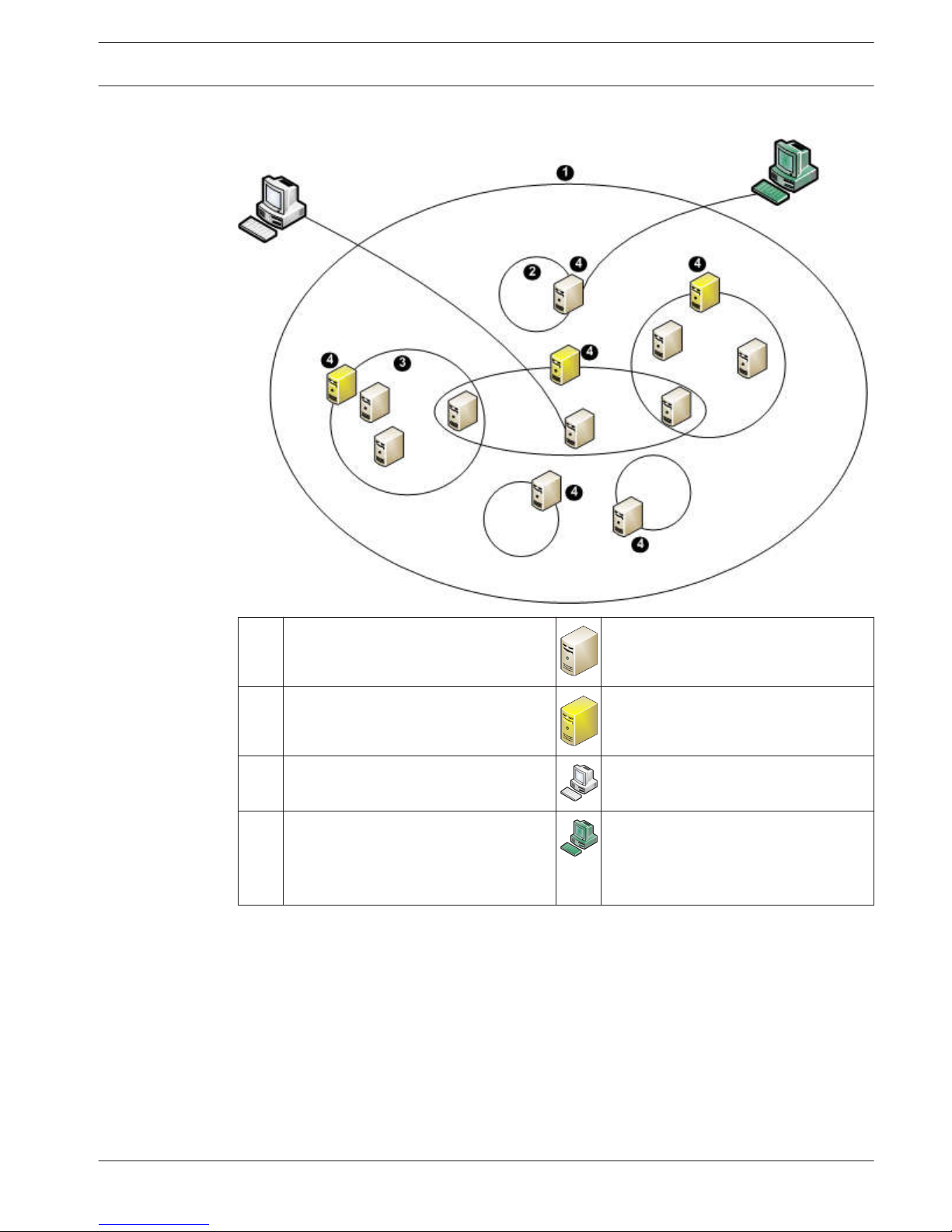
Supported system structures
An operator or installer can be responsible for the following system structures:
– Single server system
– Multi server system (Enterprise System)
– Multi system environment
System with access point for logon
Single server system,
System access point: Management Server
Enterprise System,
System access point: Enterprise Management Server
3.2
3.3
3.4
18 en | System overview Bosch Video Management System
2013.03 | V1 | Configuration Client Configuration Manual Bosch Sicherheitssysteme GmbH
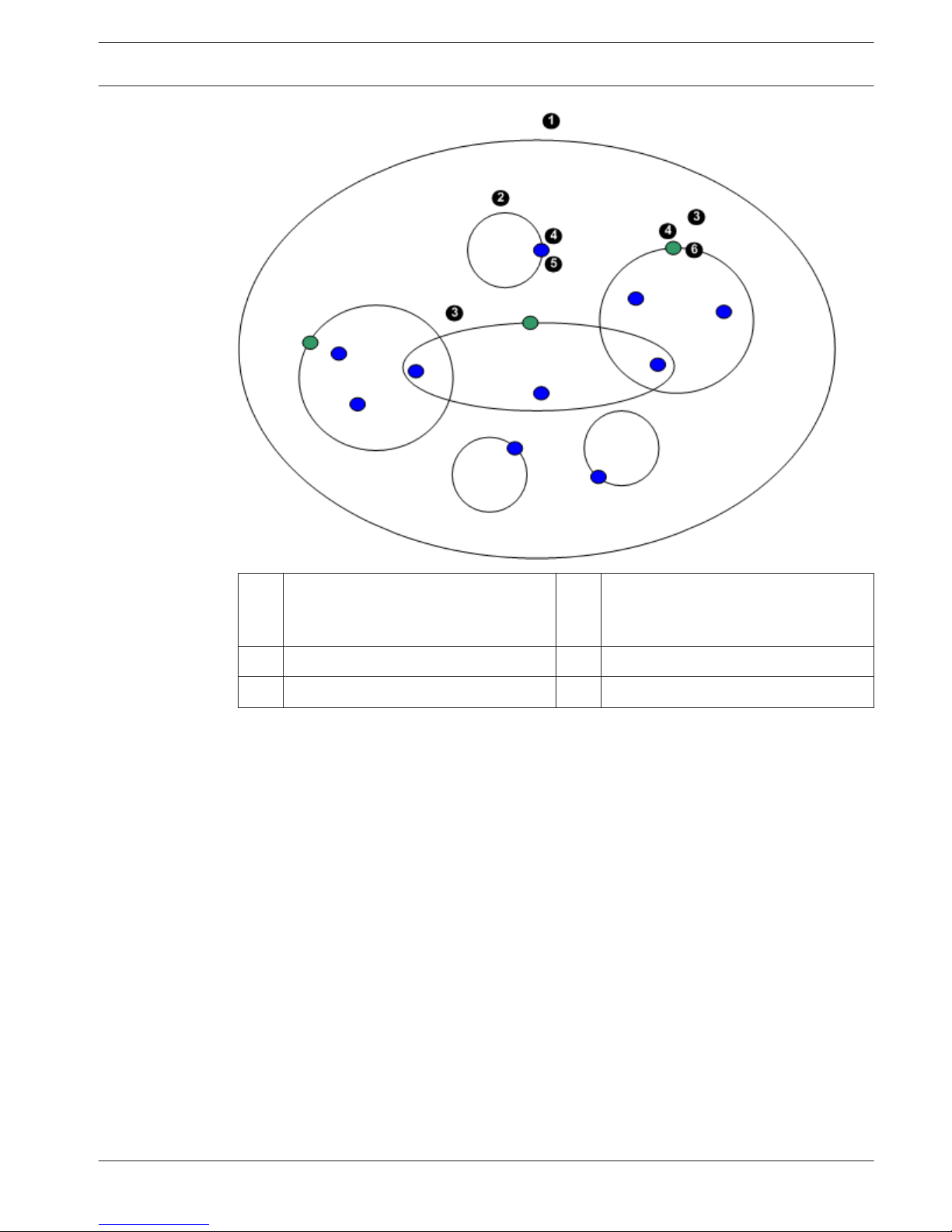
1 Multi system environment 4 System access point:
Server on which logon request of an
operator or installer is processed.
2 Single server system 5 Management Server
3 Multi server system 6 Enterprise Management Server
Use cases for multi system access
Two Bosch VMS features valid for multi system environments are available:
– Enterprise System
– Server Lookup
An operator might want to access a multi system environment for the following reasons:
– Configure multiple systems (Server Lookup)
– Maintenance and monitoring of multiple systems (Server Lookup)
– Alert (SMS, Email 3rd party) driven on-demand monitoring of multiple systems (Server
Lookup)
– Simultaneous connection to multiple servers for seamless operation of one distributed
system (Enterprise System)
Related Topics
– Enterprise System, page 20
– Server Lookup, page 24
Bosch Video Management System
System overview | en 19
Bosch Sicherheitssysteme GmbH Configuration Manual 2013.03 | V1 | Configuration Client

Concepts
This chapter provides background information on selected issues.
Configuration Wizard
Intended use for Configuration Wizard is the quick and easy configuration of a smaller system.
Configuration Wizard helps you to achieve a configured system including VRM, iSCSI system,
cameras, recording profiles and user groups.
User groups and their permissions are configured automatically. You can add or remove users
and set passwords.
Configuration Wizard can access Management Server only on the local computer.
You can save an activated configuration for backup purposes and import this configuration
later. You can change this imported configuration after import.
You must add iSCSI systems manually.
Configuration Wizard adds the local VRM automatically.
Related Topics
– Using Configuration Wizard, page 44
Enterprise System
The target of a Bosch VMS Enterprise System is to enable a user of Operator Client to
simultaneously access multiple Management Servers.
Related Topics
– Configuring the Server List for Enterprise System, page 58
– Configuring users, permissions and Enterprise Access, page 107
– Accessing the system, page 54
Scenarios
The following three scenarios are covered.
– Scenario 1: A dedicated server plays the role of Enterprise Management Server. This
server has the only task to manage the simultaneous access of an Operator Client
workstation to multiple Management Servers.
An Operator Client workstation logs on to Enterprise Management Server. After successful
logon the user of Operator Client has access to the devices of all configured Management
Servers according to the permissions in his Enterprise User Group.
4
4.1
4.2
4.2.1
20 en | Concepts Bosch Video Management System
2013.03 | V1 | Configuration Client Configuration Manual Bosch Sicherheitssysteme GmbH
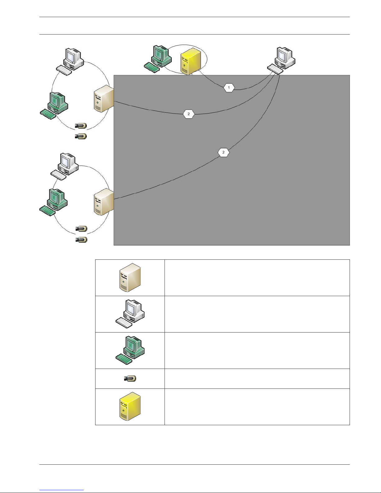
Figure 4.1: Enterprise Scenario 1
Management Server
Operator Client
Configuration Client
IP camera / encoder
Enterprise Management Server
Bosch Video Management System Concepts | en 21
Bosch Sicherheitssysteme GmbH Configuration Manual 2013.03 | V1 | Configuration Client
– Scenario 2: Combination of Enterprise Management Server and Management Server role.
In this case the own Management Server must also be part of the Enterprise Management
Server configuration.
Figure 4.2: Enterprise Scenario 2
/
Management Server / Enterprise Management Server
Operator Client
Configuration Client
IP camera / encoder
– Scenario 3: The classic client-server architecture remains supported.
22 en | Concepts Bosch Video Management System
2013.03 | V1 | Configuration Client Configuration Manual Bosch Sicherheitssysteme GmbH
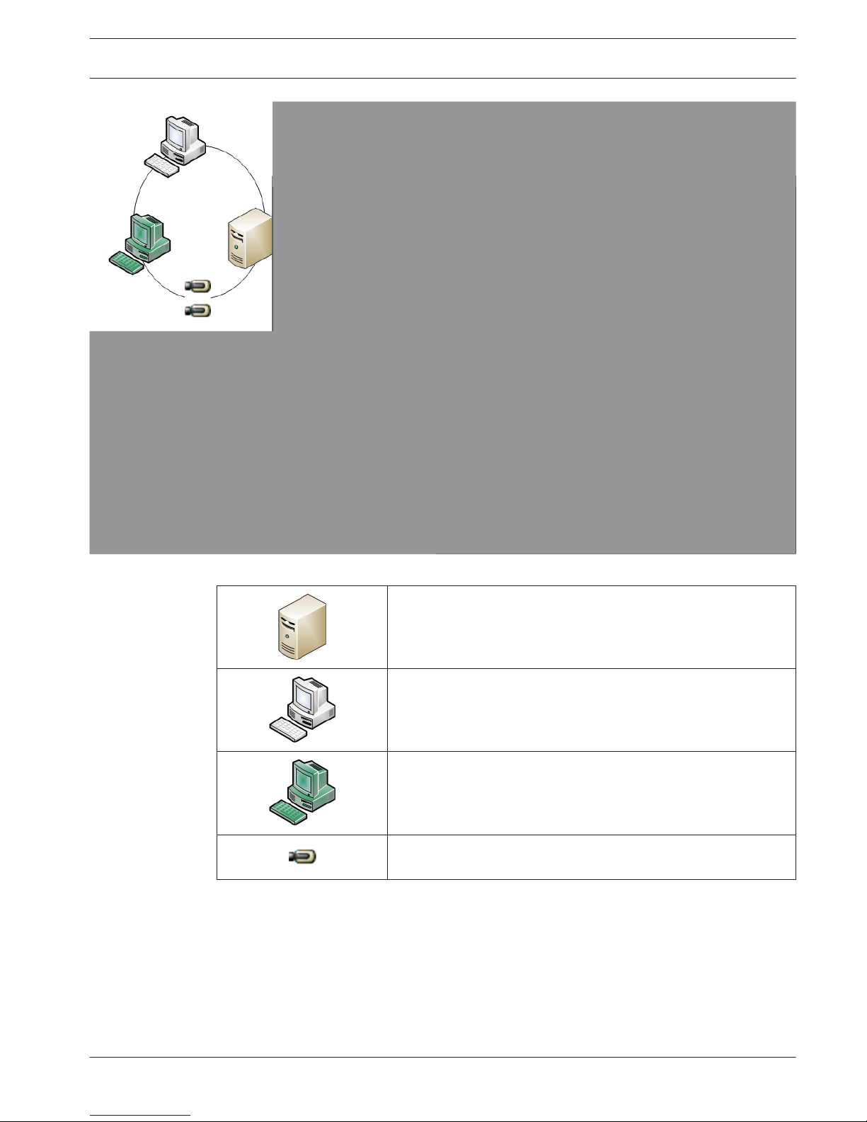
Figure 4.3: Classic Scenario 3
Management Server
Operator Client
Configuration Client
IP camera / encoder
Permissions
Permissions on an Enterprise System
For an Enterprise System you configure the following permissions:
– Operating permissions of Operator Client defining the user interface for operating in the
Enterprise System, for example the user interface of the alarm monitor.
Use an Enterprise User Group. Configure it on the Enterprise Management Server.
4.2.2
Bosch Video Management System Concepts | en 23
Bosch Sicherheitssysteme GmbH Configuration Manual 2013.03 | V1 | Configuration Client

– Device permissions that should be available for operating in an Enterprise Management
Server are defined on each Management Server.
Use Enterprise Accounts. Configure it on each Management Server.
Permissions on a single Management Server
For managing the access to one of the Management Servers, use the standard user group. You
configure all permissions on this Management Server in this user group.
You can configure dual authorization user groups for standard user groups and for Enterprise
User Groups.
Types of user groups
Type Contains Available configuration
settings
Where do you
configure?
User group Users – Operating and device
permissions
– Management
Server
Enterprise User
Group
Users – Operating permissions
– Per Management
Server: Name of the
corresponding
Enterprise Access
Accounts with logon
credentials
– Enterprise
Management
Server
Enterprise Access – – Device permissions
– Account password
– Management
Server
Dual authorization
user group
User groups – See user groups – See user groups
Enterprise dual
authorization
Enterprise User
Groups
– See Enterprise User
Groups
– See Enterprise
User Groups
Table 4.1: User groups
Licensing
Bosch VMS Enterprise (MBV-BENT) version license is required at each Enterprise Management
Server to enable the feature.
For each Management Server assigned to one or more Enterprise User Groups, 1 license
(MBV-XSUB) is required.
To update an existing MBV-BPRO Base license to an Enterprise System, you need an
Enterprise Upgrade license (MBV-FEUP).
Each Workstation connecting to an Enterprise Management Server requests one MBV-XWST
that is licensed at Enterprise Management Server. No additional MBV-XWST license is required
on each Management Server if accessed via Enterprise Management Server.
Server Lookup
A single user of Configuration Client or Operator Client may want to connect to multiple
system access points sequentially. This access is called Server Lookup. System access points
can be Management Server or Enterprise Management Server.
Server Lookup supports you in locating system access points by their names or descriptions.
The user retrieves the list of system access points during logon. He needs to connect to the
server hosting the configuration with Server List (Server List Provider).
4.2.3
4.2.4
4.3
24 en | Concepts Bosch Video Management System
2013.03 | V1 | Configuration Client Configuration Manual Bosch Sicherheitssysteme GmbH
The following image shows an example for Server Lookup in a multi system environment:
1 Multi system environment Management Server
2 Single server system Enterprise Management Server
3 Multi server system Operator Client
4 System access point:
Server on which logon request of
Operator Client or Configuration Client
is processed.
Configuration Client
When a client logs on to Enterprise Management Server, it is possible to get access to all
Management Servers of this Enterprise System simultaneously.
Related Topics
– Configuring Server Lookup, page 59
– Server List page, page 135
– Using Server Lookup, page 54
Remote access
The target of remote access in Bosch VMS is to connect different private networks to public
networks.
4.4
Bosch Video Management System Concepts | en 25
Bosch Sicherheitssysteme GmbH Configuration Manual 2013.03 | V1 | Configuration Client
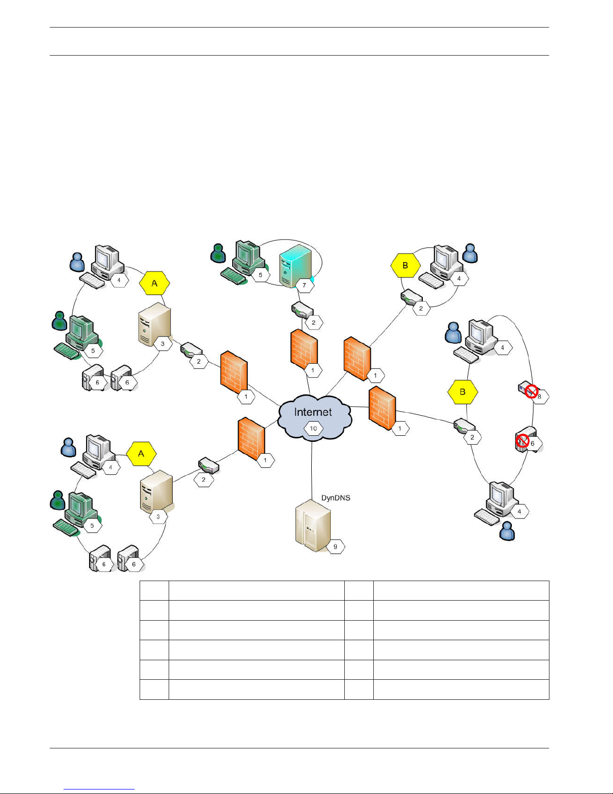
Multiple networks with private (local) network addresses can be accessed simultaneously or
sequentially by Operator Client computers via public interfaces (routers). Task of the router is
to translate the incoming public network traffic to the corresponding private network address.
The users of Operator Client can access Management Server or Enterprise Management Server
and their devices via remote access.
You cannot access the following devices/features via remote access:
– Playback of local storage
– ONVIF
– DiBos
– Direct iSCSI replay
The following image shows an example of remote access to Bosch VMS devices in a single
system:
1
Firewall 6 IP camera / encoder
2 Router 7 Enterprise Management Server
3 Management Server 8 Decoder
4 Operator Client 9 DynDNS Server
5 Configuration Client 10 World Wide Web
A Remote network B Local network
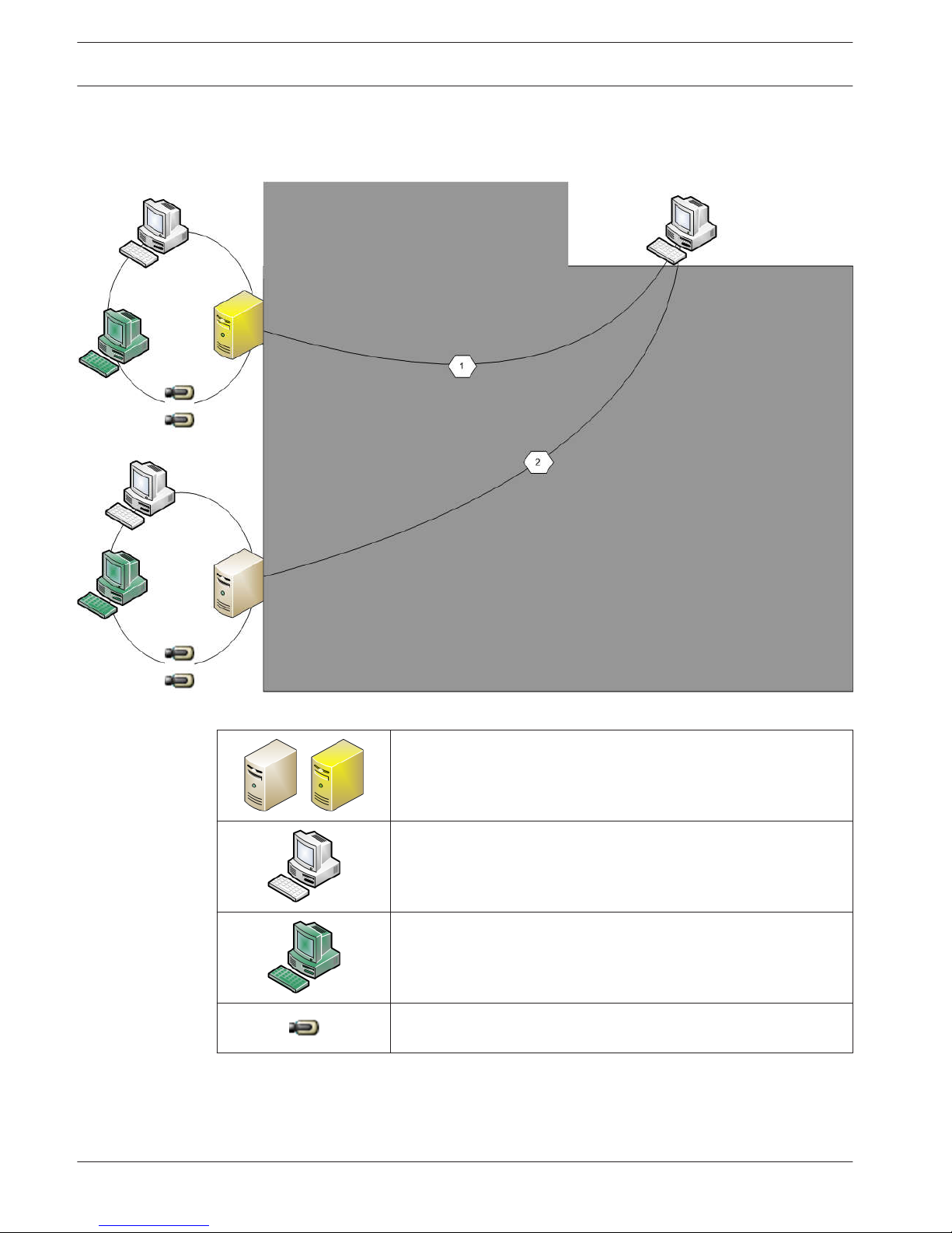
The following image shows an example of remote access from private network with Enterprise
System to remote Bosch VMS systems:
26 en | Concepts Bosch Video Management System
2013.03 | V1 | Configuration Client Configuration Manual Bosch Sicherheitssysteme GmbH
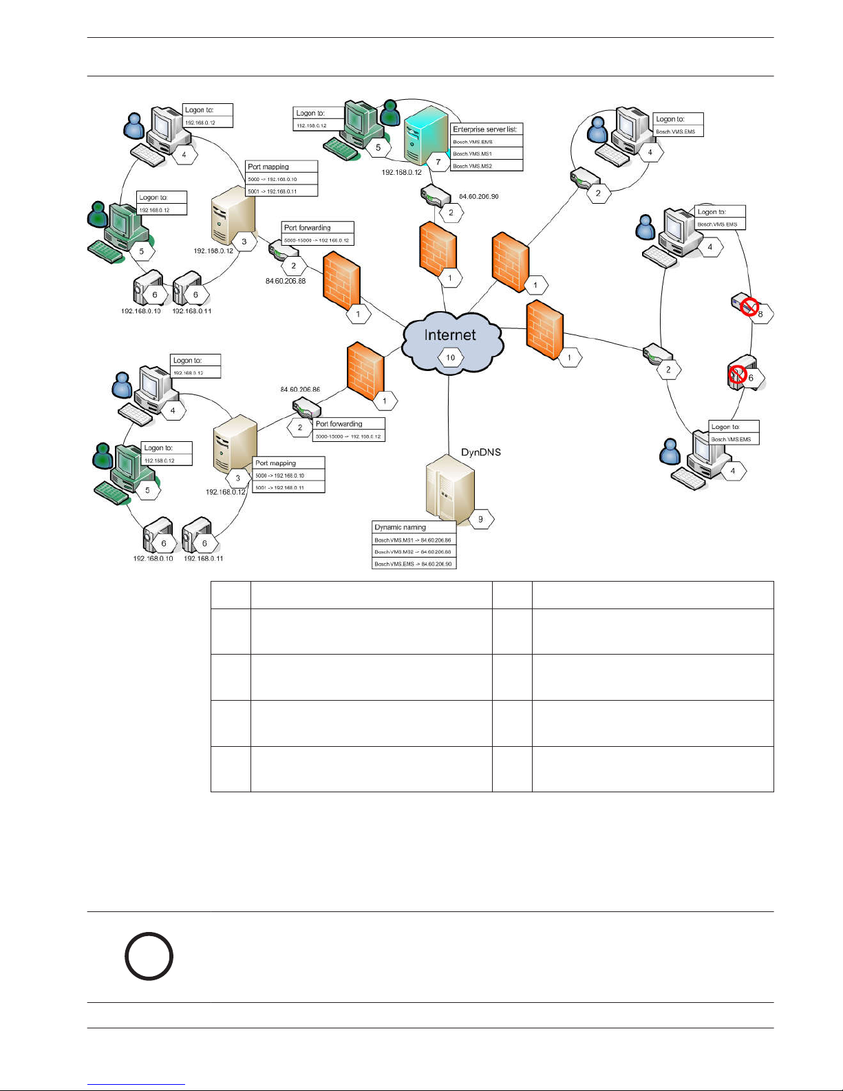
1 Firewall 6 IP camera / encoder
2 Router
Port forwarding
7 Enterprise Management Server
Enterprise server list
3 Management Server
Port mapping
8 Decoder
4 Operator Client
Logon to
9 DynDNS Server
Dynamic naming
5 Configuration Client
Logon to
10 World Wide Web
To enable the remote access of an Operator Client to devices in a remote network, each
device is assigned a public port number in addition to the public network address of the
router. For access, Operator Client uses this public port number together with the public
network address. In the private network the incoming traffic for the public port number is
forwarded to the private network address and port number of the corresponding device.
You configure the port mapping in Configuration Client for use by Operator Client.
i
Notice!
Additionally the network administrator must configure the port forwarding on the router of
the private network. The network administrator must ensure that remote access via these
ports is running outside of Bosch VMS environment.
Bosch Video Management System Concepts | en 27
Bosch Sicherheitssysteme GmbH Configuration Manual 2013.03 | V1 | Configuration Client

Related Topics
– Configuring remote access, page 54
– Remote Access Settings dialog box, page 132
– Show Port Mapping dialog box, page 132
iSCSI storage pool
As of VRM v.3.0, iSCSI storage pools are introduced. A storage pool is a container for one or
more iSCSI storage systems that share the same load balancing properties. The encoders / IP
cameras that are assigned to a storage pool, are recorded with these common load balancing
settings.
A storage pool can be used to have a logical mapping of the network topology to the VRM, for
example if you have two buildings, both containing storage and devices, you want to avoid
routing the network traffic from one building to the other.
Storage pools can also be used to group cameras and storage systems by an important aspect
of view. For example a system contains of some very important cameras and a lot of less
important ones. In this case it is possible to group them into two storage pools, one with a lot
of redundancy features and one with less redundancy.
You can configure the following load balancing properties for a storage pool:
– Recording preferences (Automatic or Failover)
– Secondary target usage
Secondary target is used in case of Failover mode if the assigned primary target fails. If
this option is turned off, the recording stops on all devices assigned to this failed primary
target.
In case of Automatic mode: if one target fails, VRM Server performs an automatic
reassign of the related devices to other storages. If VRM Server is down while a target
fails, the recording is stopped on the devices currently recording on the failed target.
– Block reservation for downtime
– Sanity check period
i
Notice!
In Bosch VMS v. 4.5, one storage pool per VRM is supported.
Click below to get detailed information on the available pages:
– Pool page, page 161
Alarm handling
Alarms can be individually configured to be handled by one or more user groups. When an
alarm occurs, it appears in the Alarm List of all users in the user groups configured to receive
that alarm. When any one of these users starts to work on the alarm, it disappears from the
Alarm List of all other users.
Alarms are displayed on a workstation’s alarm monitor and optionally on analog monitors. This
behavior is described in the following paragraphs.
Alarm flow
1. An alarm occurs in the system.
2. Alarm notifications appear in the Alarm Lists of all users configured for this alarm. Alarm
video is immediately displayed on configured monitors. If it is an automatically displayed
alarm (auto pop-up), the alarm video is also automatically displayed on the Operator
Client workstation’s alarm monitors.
If the alarm is configured as an auto-clear alarm, the alarm is removed from the Alarm List
4.5
4.6
28 en | Concepts Bosch Video Management System
2013.03 | V1 | Configuration Client Configuration Manual Bosch Sicherheitssysteme GmbH

after the auto-clear time (configured in the Configuration Client).
On analog monitors, any quad views from VIP XDs are temporarily replaced by full-screen
displays.
3. One of the users accepts the alarm. The alarm video is then displayed on this user's
workstation (if it is not already displayed via auto pop-up). The alarm is removed from all
other Alarm Lists and alarm video displays.
4. The user who accepted the alarm invokes a workflow that can include reading an action
plan and entering comments. This step is optional - requirements for workflow can be
configured by the administrator.
5. Finally, the user clears the alarm. This removes the alarm from his Alarm List and alarm
display.
On an analog monitor group, the monitors return to the cameras that were displayed
before the alarm occurred.
Alarm Image window
1. To display alarm video, the Alarm Image window replaces the Live or Playback Image
window on the monitor that has been configured for alarm display.
2. Each alarm gets a row of Image panes. Up to 5 Image panes can be associated with each
alarm. These Image panes can display live video, playback video, or maps.
On an analog monitor group, each alarm can call up cameras on a row of analog monitors.
The number of cameras in the row is limited by the number of columns in the analog
monitor group. Monitors in the row that are not used for alarm video can be configured to
either continue with their current display or to display a blank screen.
3. Higher priority alarms are displayed above lower priority alarms on both analog monitor
rows and the Operator Client workstation display alarm rows.
4. If the Alarm Image window is completely full of Alarm Image rows and an additional alarm
must be displayed, the lowest priority alarms "stack up" in the bottom row of the Alarm
Image window. You can step through the stacked alarms with the controls at the left side
of the alarm row.
You can step through the alarm stacks on analog monitor groups with control buttons in
the Monitors window of the Operator Client workstation display. Analog monitors in
alarm are indicated by red icons with blinking "LEDs".
The alarm title, time, and date can be optionally be displayed on all analog monitors, or
only the first monitor in the alarm row.
5. For equal priority alarms, the administrator can configure the order behavior:
– Last-in-First-out (LIFO) mode: in this configuration, new alarms are inserted above
older alarms of the same priority.
– First-in-First-out (FIFO) mode; in this configuration, new alarms are inserted below
older alarms of the same priority.
6. An alarm's Image row can appear in the Alarm Image window in one of two ways:
– When it is generated (auto pop-up). This occurs when the alarm priority is higher
than display priority.
– When the alarm is accepted. This occurs when the alarm priority is lower than
display priority.
Auto pop-up alarms
Alarms can be configured to automatically display (pop up) in the Alarm Image window, based
on the alarm priority. Each user group's live and playback displays are also assigned priorities.
When alarms are received with priority higher than that of the user's display, the alarm
Bosch Video Management System
Concepts | en 29
Bosch Sicherheitssysteme GmbH Configuration Manual 2013.03 | V1 | Configuration Client

automatically displays its alarm row in the Alarm Image window. If the Alarm Image window is
not currently displayed, it automatically replaces the Live or Playback Image window on the
alarm-enabled monitor.
Although auto pop-up alarms are displayed in the Alarm Image window, they are not
automatically accepted. They can be displayed on multiple users' displays simultaneously.
When a user accepts an auto pop-up alarm, it is removed from all other users Alarm Lists and
alarm displays.
Related Topics
– Handling alarms
DVR devices
This chapter gives background information on the DVR devices that you can integrate in
Bosch VMS.
Some DVR models (e.g. DHR-700) support recording from encoders / IP cameras. Other DVR
models support only analog cameras.
An encoder / IP camera should not be integrated into the configuration of two video systems
(DVRs or video management systems).
If encoders / IP cameras are connected to a DVR which is already integrated in Bosch VMS,
these encoders / IP cameras are not detected by the Bosch VMS network device scan. This
holds true for the network scan started from within Configuration Client or started from
within Configuration Wizard.
If a DVR with connected encoders / IP cameras is integrated in Bosch VMS and these
encoders / IP cameras are already added to Bosch VMS, a warning is displayed. Remove these
encoders / IP cameras from the DVR or from Bosch VMS.
Configuration Wizard does not add DVR devices with conflicting IP cameras to the
configuration.
DVR devices support a limited number of simultaneous connections. This number defines the
maximum number of Operator Client users that can simultaneously display videos from this
DVR without black Image panes being displayed.
Related Topics
– DVR (Digital Video Recorder) page, page 144
Mobile Video Service
Mobile Video Service is transcoding video streams from the source to the available band-width
of connected clients. The interfaces of the Mobile Video Service are designed to support
clients on multiple platforms, for example Mobile devices (IOS; iPad, iPhone) and Windows
Internet Explorer HTML client.
Mobile Video Service is based on Microsoft Internet Information Service.
One mobile service may serve several clients synchronously.
For limits refer to data sheet and the Technical Note Mobile Video Service available in the
Online Product Catalog for Bosch VMS.
Internet Information Service
Configure the settings for Internet Information Service on the computer where you plan to
install MVS for Bosch VMS.
Install and configure Internet Information Service (IIS) before you install Mobile Video Service
(MVS). If IIS is not installed, Bosch VMS Setup to install Mobile Video Service aborts.
You select the Mobile Video Service component for installation during Bosch VMS Setup.
You cannot install Video Recording Manager (VRM) and Mobile Video Service on the same
computer.
4.7
4.8
30 en | Concepts Bosch Video Management System
2013.03 | V1 | Configuration Client Configuration Manual Bosch Sicherheitssysteme GmbH

We recommend that you do not install Mobile Video Service on the same computer where you
install Management Server.
Related Topics
– Adding a Mobile Video Service, page 75
– Mobile Video Service page, page 159
Bosch Video Management System Concepts | en 31
Bosch Sicherheitssysteme GmbH Configuration Manual 2013.03 | V1 | Configuration Client

Supported hardware
!
Caution!
Do not connect a device to more than one Bosch VMS! This can lead to recording gaps and
other undesired effects.
You can connect the following hardware to Bosch VMS:
– Mobile video clients like iPhone or iPad via DynDNS
– Various IP cameras. encoders and ONVIF cameras (live only or via Video Streaming
Gateway)
Connected via network
– Live only encoders with local storage
Connected via network
– iSCSI storage devices
Connected via network
– VIDOS NVR computer
Connected via network
– Analog cameras
Connected to encoders, BRS / DiBos devices
– Decoders
Connected via network
– Analog monitors
Connected to a decoder, to a Bosch Allegiant matrix, to a Bosch VMS Client workstation
– BRS / DiBos devices (see the data sheet for Bosch VMS for supported software versions)
Connected via network
– Bosch Allegiant matrix (Firmware version: 8.75 or greater, MCS version: 2.80 or greater)
Connected to a COM port of the Management Server or to a remote computer and to an
IP encoder on the network.
– VideoTec DCZ keyboard
Connected to a USB port of a Bosch VMS workstation.
– Bosch IntuiKey keyboard
Connected to the COM port of a Bosch VMS workstation (Firmware version: 1.82 or
greater) or to a hardware decoder (VIP XD).
If you connect the keyboard to a workstation, the user can control the complete system
with the keyboard. If you connect the keyboard to a VIP XD decoder, the user can only
control analog monitors with the keyboard.
– SMS device
Connected to a COM port of the Management Server
– SMTP E-mail server
Connected via network
– POS
Connected via network
– ATM
Connected via network
– Network monitoring device
Connected via network
– I/O modules
Connected via network
Only ADAM devices are supported.
5
32 en | Supported hardware Bosch Video Management System
2013.03 | V1 | Configuration Client Configuration Manual Bosch Sicherheitssysteme GmbH

All devices connected via network are connected to a switch. The computers of the Bosch
VMS are also connected to this device.
Installing hardware
Bosch VMS supports the following hardware components:
– VideoTec DCZ keyboard
– Bosch IntuiKey keyboard
– Bosch Allegiant matrix with cameras and monitor: Connected to a COM port of one of the
computers of the network and to IP encoders connected to the network
– Encoders with analog cameras
– Local storage encoders
– IP cameras and IP AutoDomes
– Monitors connected to a decoder (analog monitor groups for alarm processing are
possible)
– DiBos Systems with cameras
– DVR Systems with cameras
– ATM / POS devices
– I/O modules
Only ADAM devices are supported.
Connecting a Bosch IntuiKey keyboard to Bosch VMS
This chapter provides background information on configuring a Bosch IntuiKey keyboard.
Scenarios for Bosch IntuiKey keyboard connections
You can connect a Bosch IntuiKey keyboard to the COM port of a Bosch VMS workstation
(scenario 1) or to a hardware decoder (e.g. VIP XD, scenario 2).
If you connect the keyboard to a Bosch VMS workstation, you can control the complete
system. If you connect the keyboard to a decoder, you can only control the analog monitors of
the system.
If you connect the keyboard to an Enterprise Operator Client, you can control the cameras of a
specific Management Server by first pressing the server key to type in the number of this
server and then type the camera number.
i
Notice!
For connecting the Bosch IntuiKey keyboard with a Bosch VMS workstation, use the specified
Bosch cable.
For connecting the Bosch IntuiKey keyboard with a VIP XD decoder, you need a cable which
connects a serial COM port of the keyboard with the serial interface of the decoder. See Con-
necting a CCTV keyboard to a decoder for connections.
5.1
5.2
5.2.1
Bosch Video Management System Supported hardware | en 33
Bosch Sicherheitssysteme GmbH Configuration Manual 2013.03 | V1 | Configuration Client

Bosch IntuiKey keyboard connected to a Bosch VMS workstation
Figure 5.1: Scenario 1: Bosch IntuiKey keyboard connected to a Bosch Video Management System
workstation
1
Various cameras connected to network via encoders
2 Bosch VMS workstation
3 Bosch IntuiKey keyboard
4 Bosch VMS network
5 Decoder
6 Analog monitors
34 en | Supported hardware Bosch Video Management System
2013.03 | V1 | Configuration Client Configuration Manual Bosch Sicherheitssysteme GmbH

Bosch IntuiKey keyboard connected to a decoder
Figure 5.2: Scenario 2: Bosch IntuiKey keyboard connected to a decoder
1
Various cameras connected to network via encoders
2 Bosch VMS workstation
3 Bosch VMS network
4 Bosch IntuiKey keyboard
5 Decoder
6 Analog monitors
Follow these references to get detailed information on the available windows:
– Assign Keyboard page, page 157
Follow these references to get detailed information on the available step-by-step instructions:
– Configuring a Bosch IntuiKey keyboard (workstation), page 74
– Configuring a Bosch IntuiKey keyboard (decoder), page 74
– Configuring a decoder for use with a Bosch IntuiKey keyboard, page 69
Connecting a Bosch IntuiKey keyboard to a decoder
Configuring the decoder
See Configuring a decoder for use with a Bosch IntuiKey keyboard, page 69 for details.
Connections between COM port and VIP XD decoder
The following table lists the connections between an RS232 adapter and a serial interface of a
VIP XD decoder:
RS232 adapter Serial interface of a VIP XD decoder
1
2 TX
5.2.2
Bosch Video Management System Supported hardware | en 35
Bosch Sicherheitssysteme GmbH Configuration Manual 2013.03 | V1 | Configuration Client

RS232 adapter Serial interface of a VIP XD decoder
3 RX
4
5 GND
6
7 CTS
8 RTS
9
The following illustration shows the pinout of a standard RS232 adapter (1) and the pinout of
the decoder’s serial adapter (2):
21
12345
6789
Updating Bosch IntuiKey keyboard firmware
1. On any PC, install the IntuiKey downloader.
2. Start IntuiKey Firmware Upgrade Utility.
3. Connect the keyboard with a valid serial cable (refer to Bosch Support if such a cable is
not available) to this PC.
4. On the keyboard, press Keyboard Control softkey, then Firmware Upgrade.
5. Enter the password: 0 and 1 simultaneously.
The keyboard is in bootloader mode.
6. On the PC, click Browse to select the firmware file: for example kbd.s20
7. Set the COM port.
8. Click the Download button to download the firmware.
On the keyboard display, Programming is displayed.
Do not press the Clr key now. Otherwise the keyboard is not usable after restart (see
Notice below).
9. Click Browse to select the language: for example 8900_EN_..82.s20
On the keyboard display, Programming is displayed.
10. Close IntuiKey Firmware Upgrade Utility.
11. On the keyboard, press Clr key to exit.
The keyboard restarts. Wait some seconds until the menu for selecting the keyboard
language appears.
12. Select the desired language with a softkey.
The default start display appears.
5.2.3
36 en | Supported hardware Bosch Video Management System
2013.03 | V1 | Configuration Client Configuration Manual Bosch Sicherheitssysteme GmbH

i
Notice!
For starting the bootloader mode directly, you can unplug the power supply from the key-
board, press 0 and 1 simultaneously, plug In the power supply again, release 0 and 1.
Connecting Bosch Allegiant Matrix to Bosch Video
Management System
The Bosch VMSAllegiant Matrix interface provides seamless access to analog matrix cameras
in the Operator Client interface. Allegiant cameras appear almost identical to IP cameras. The
only difference is a small grid symbol on the camera to indicate that it is a Allegiant camera.
You can display cameras using the same tasks as for IP cameras. They are included both in the
Logical Tree and the site maps, and users can add them to their Favorites Trees. In-videowindow control for Allegiant-connected PTZ cameras is supported, and you can easily display
Allegiant cameras on analog monitors connected to IP decoders.
Bosch VMS provides an interface to the matrix switch via the Allegiant MCS (Master Control
Software) application). The MCS, in this case, runs invisibly in the background. This software
provides an efficient, event-driven interface to the Allegiant. It provides fast, real-time event
response from the Allegiant to Bosch VMS. So, for example, if a defective coax cable results in
video loss in the Allegiant, an immediate notification is sent to Bosch VMS. Also, you can
program Bosch VMS to respond to Allegiant alarms.
Bosch Allegiant Connection Overview
To achieve a connection between Bosch VMS and an Allegiant matrix switching system, you
configure a control channel between the Bosch VMS and the Allegiant matrix.
Two scenarios are possible:
– Local connection
The Management Server controls the Allegiant matrix.
– Remote connection
A dedicated Bosch Allegiant PC connected to the network controls the Allegiant matrix.
5.3
5.3.1
Bosch Video Management System Supported hardware | en 37
Bosch Sicherheitssysteme GmbH Configuration Manual 2013.03 | V1 | Configuration Client

Local connection
Figure 5.3: Bosch Video Management System local connection to a Bosch Allegiant matrix switch
1 Bosch VMS Client workstations
2 Management Server with Master Control Software
3 RS-232 connection
4 Allegiant matrix
5 encoders
6 Network
Remote connection
38 en | Supported hardware Bosch Video Management System
2013.03 | V1 | Configuration Client Configuration Manual Bosch Sicherheitssysteme GmbH

Figure 5.4: Bosch Video Management System remote connection to a Bosch Allegiant matrix switch
1 Bosch VMS Client workstations
2 Management Server with Master Control Software
3 Network
4 Allegiant PC with Master Control Software
5 RS-232 connection
6 encoders
7 Allegiant matrix
Configuring the control channel
Perform the following tasks to configure the control channel:
– Wiring
– Installing the software
– Creating Allegiant configuration file
– Adding the Allegiant matrix to Bosch VMS
– Configuring user names
Wiring
To configure the control channel between Bosch VMS and the Allegiant matrix, connect one
PC through an RS-232 serial port to the Allegiant's console port (use the specified Bosch cable
for connection). This can be the Bosch VMS Management Server, or any other PC on the
network.
5.3.2
Bosch Video Management System Supported hardware | en 39
Bosch Sicherheitssysteme GmbH Configuration Manual 2013.03 | V1 | Configuration Client

Installing Allegiant Master Control Software
1. Stop the Management Server service if running (Start > Control Panel > Services > Rightclick Bosch VMS Management Server > Stop)
2. Install the Allegiant Master Control Software on the Management Server and on the
Allegiant PC (if present).
3. On an remote Allegiant PC configure it to start the Allegiant Network Host program
(ld_alghw.exe) on startup. This starts the necessary Allegiant services to allow other PCs
on the network to access the Allegiant. The software runs invisibly. It is not necessary to
have a dongle attached to this computer.
To have the service started on computer startup automatically, copy a link to
ld_alghw.exe to the Startup folder of your computer.
Creating a Bosch Allegiant configuration file
1. Using the Allegiant Master Control Software, create a Allegiant configuration file that
specifies the computer attached to the Allegiant matrix. For this task, the Master Control
dongle is required.
2. On the Transfer menu, click Communication Setup. In the Current Host list, enter the
DNS name of the computer connected to the Allegiant matrix, and enter the serial port
parameters (COM port number, baud rate, etc.) of the Allegiant-connected serial port.
This allows the Master Control Software on the Management Server or PC to go on-line
with the Allegiant system. If this is not successful, ensure that either the Master Control
Software or the Allegiant Network Host program is running on the computer attached to
the Allegiant matrix, and that the network security is configured to allow remote access
to this computer.
3. On the Transfer menu, click Upload. Select all tables and click Upload. To save the
configuration file, select a directory.
4. Exit the Master Control Software.
Adding the Bosch Allegiant matrix to Bosch VMS
1. Start the Bosch VMS Management Server service, start the Configuration Client, and add
the Allegiant device by adding this configuration file (see Adding a device, page 65 for
the step-by-step instruction).
2. Ensure that the Allegiant Master Control Software configuration file used in Bosch VMS
matches the current Allegiant configuration.
Bosch VMS runs the required components of Master Control Software invisibly in the
background.
Configuring the user name for logging on the Allegiant services
If the Allegiant matrix is connected to a PC in the network and not to the Management Server,
ensure that the Allegiant services on this PC and on the Management Server log on with the
same user account. This user must be member of an administrators group.
Further notes in the documentation
Follow these references to get detailed information on the available windows:
– Matrix Switches page, page 145
Follow these references to get detailed information on the available step-by-step instructions:
– Configuring a Bosch Allegiant device, page 71
Bosch Allegiant Satellite System Concept
The Allegiant matrix switch allows multiple Allegiant systems to be tied together using the
Satellite concept. In this case, multiple Allegiant systems can appear to the Bosch VMS as one
large system, providing access to all cameras on all systems.
5.3.3
40 en | Supported hardware Bosch Video Management System
2013.03 | V1 | Configuration Client Configuration Manual Bosch Sicherheitssysteme GmbH

In an Allegiant Satellite System, monitor outputs of a slave Allegiant are tied to video inputs on
the master Allegiant. This connection is called a trunk line. In addition, a control channel is
established between the master and the slave. When a camera from a slave Allegiant is
requested from the master Allegiant, a command is sent to the slave instructing it to switch
the requested camera to a trunk line. At the same time, the master Allegiant switches the
trunk input to the requested master Allegiant monitor output. This completes the video
connection from the requested slave camera to the desired master monitor.
Figure 5.5: Bosch Allegiant system extended with Satellite switches
1 Bosch VMS Client workstations
2 Management Server with Master Control Software
3 Network
4 Allegiant PC with Master Control Software
5 RS-232 connection
6 encoders
7 Allegiant matrix
8 Allegiant Satellite matrix
You can apply the Satellite concept such that an Allegiant can be both a master and a slave. In
this way, each Allegiant can view cameras from the others. It is only necessary to connect
trunk lines and control lines in both directions, and to properly configure the Allegiant tables.
The concept can be further extended, with no practical limit, to multiple Allegiant systems. An
Allegiant can have many slaves, and it can be a slave to many masters. You can program the
Allegiant tables to allow or disallow user access to camera views as required by site policies.
Allegiant CCL commands supported in Bosch VMS
To use the CCL commands you need the CCL User Guide. This manual is available in the
Online Product Catalog in the document section of each LTC Allegiant Matrix.
5.3.4
Bosch Video Management System Supported hardware | en 41
Bosch Sicherheitssysteme GmbH Configuration Manual 2013.03 | V1 | Configuration Client

Supported command Description Remarks
Switching/Sequence
LCM Switch Logical Camera to
Monitor
LCM, LCM+ and LCM- are
equivalent.
LCMP Switch Logical Camera to
Monitor with Pre-position
Call
MON+CAM Switch Physical Camera to
Monitor
MON-RUN Run Sequence by Monitor
Number
MON-HOLD Hold Sequence by Monitor
Number
SEQ-REQ Sequence Request
SEQ-ULD Sequence Unload
Receiver/Driver
R/D Basic Control commands
REMOTE-ACTION Simultaneous Pan/Tilt/
Zoom Control commands
REMOTE-TGL Toggle Pan/Tilt/Zoom
Control commands
PREPOS-SET Set Pre-position
PREPOS Call Pre-position
AUX-ON
AUX-OFF
Auxiliary Control
commands
– Auxiliary On
– Auxiliary Off
VARSPEED_PTZ Variable Speed Control
commands
Alarm Used to control virtual inputs. For
example "+alarm 1" closes virtual
input 1, "-alarm 1" opens virtual
input 1
+ALARM Activate an alarm Opens a virtual input in
Bosch VMS.
-ALARM Deactivate an alarm Closes a virtual input in
Bosch VMS.
System
42 en | Supported hardware Bosch Video Management System
2013.03 | V1 | Configuration Client Configuration Manual Bosch Sicherheitssysteme GmbH

Supported command Description Remarks
Switching/Sequence
TC8x00>HEX Set Hexadecimal Mode
TC8x00>DECIMAL Set Decimal Mode
Bosch Video Management System Supported hardware | en 43
Bosch Sicherheitssysteme GmbH Configuration Manual 2013.03 | V1 | Configuration Client

Getting started
This chapter provides information on how to get started with Bosch VMS and with Bosch VMS
Archive Player
Installing the software modules
Caution!
Do not install DiBos Web client on any Bosch VMS computer.
Install every software module on the computer that is supposed to be used for this module.
To install:
1. Insert the product CD-ROM.
2. Start setup.exe or start the Bosch VMS Setup on the Welcome screen.
3. In the next dialog box, select the modules to be installed on this computer.
4. Follow the instructions on the screen.
Using Configuration Wizard
To start Configuration Wizard:
4
Click Start > All Programs > Bosch VMS > Configuration Wizard.
The Welcome page is displayed.
Related Topics
– Configuration Wizard, page 20
Available pages
– Welcome page, page 45
– Select video devices to be added page, page 48
– Enter password for added devices page, page 49
– Select a recording profile page, page 50
– Add additional storage page, page 51
– User accounts and passwords page, page 52
– Activate Configuration page, page 53
6
6.1
6.2
44 en | Getting started Bosch Video Management System
2013.03 | V1 | Configuration Client Configuration Manual Bosch Sicherheitssysteme GmbH

Welcome page
If the connection to the Management Server cannot be established, a corresponding error
message is displayed. You cannot continue working with Configuration Wizard.
If VRM is not available on the computer, a corresponding error message is displayed. You
cannot continue working with Configuration Wizard.
If the license check fails, a corresponding error message is displayed. You cannot continue
working with Configuration Wizard.
Bosch Video Management System Getting started | en 45
Bosch Sicherheitssysteme GmbH Configuration Manual 2013.03 | V1 | Configuration Client

46 en | Getting started Bosch Video Management System
2013.03 | V1 | Configuration Client Configuration Manual Bosch Sicherheitssysteme GmbH

Video settings page
This page displays the latest saved configuration. You can import a .bvms file as a change to
the existing configuration. This change is saved but not activated when you click Next.
You can select the network adapter of your computer that is connected to the video devices
(IP cameras, encoders, decoders, iSCSI storage systems) of your system. The IP address of
this network adapter is used as IP address of the VRM, the VSG and the local iSCSI storage
system.
Bosch Video Management System Getting started | en 47
Bosch Sicherheitssysteme GmbH Configuration Manual 2013.03 | V1 | Configuration Client
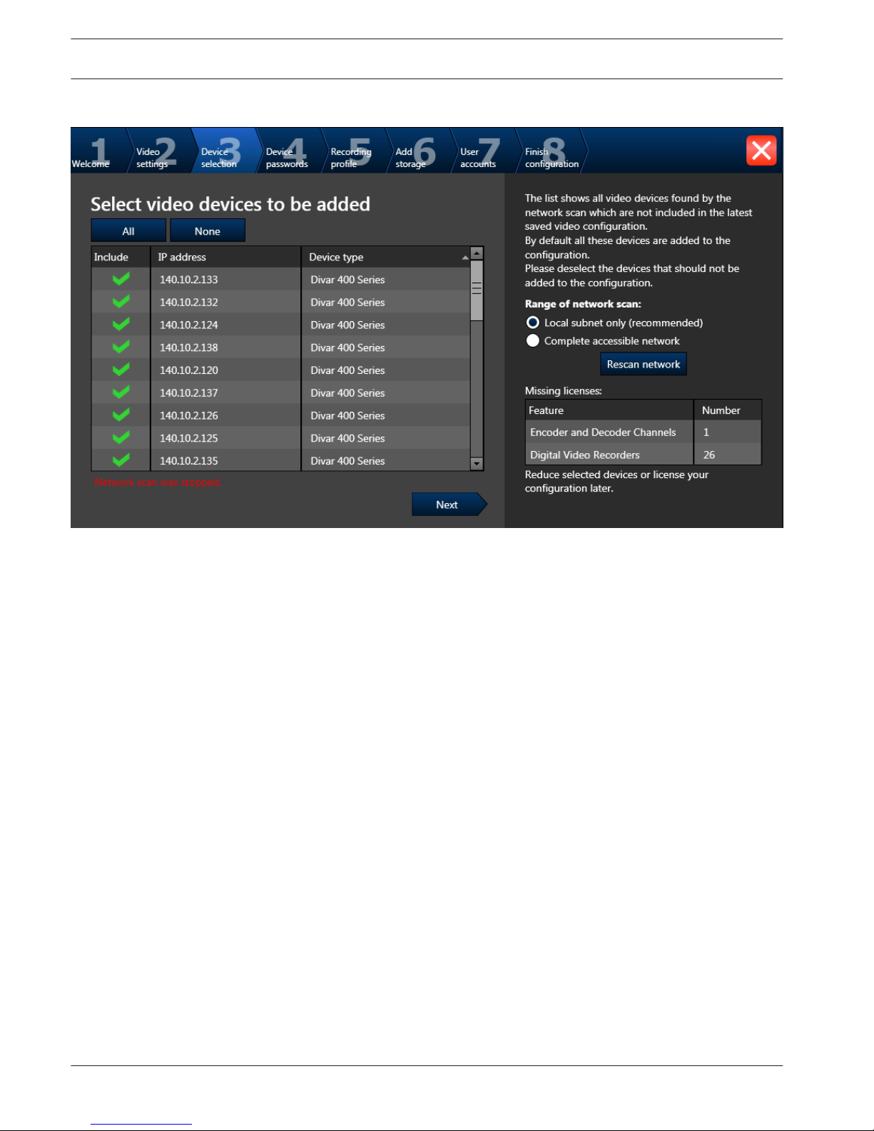
Select video devices to be added page
This page displays all network devices that are already added to the system.
If you import a configuration, the time and network settings are not affected.
For multi-channel encoders, the recording profile is displayed as (non-uniform), if applicable.
Clicking Next starts scanning for devices.
48 en | Getting started Bosch Video Management System
2013.03 | V1 | Configuration Client Configuration Manual Bosch Sicherheitssysteme GmbH

Enter password for added devices page
Password check is performed automatically, when you do not enter a character in a password
field for a few seconds or you click outside the password field.
Bosch Video Management System Getting started | en 49
Bosch Sicherheitssysteme GmbH Configuration Manual 2013.03 | V1 | Configuration Client

Select a recording profile page
For different profile assignments to different cameras you must execute Configuration Wizard
multiple times.
50 en | Getting started Bosch Video Management System
2013.03 | V1 | Configuration Client Configuration Manual Bosch Sicherheitssysteme GmbH

Add additional storage page
If no iSCSI system is available on your system, you can add it manually in Configuration
Wizard.
If VRM is not already being added to the configuration, Configuration Wizard adds it
automatically using the IP address of your system.
Bosch Video Management System Getting started | en 51
Bosch Sicherheitssysteme GmbH Configuration Manual 2013.03 | V1 | Configuration Client

User accounts and passwords page
You can add users, you cannot add user groups.
52 en | Getting started Bosch Video Management System
2013.03 | V1 | Configuration Client Configuration Manual Bosch Sicherheitssysteme GmbH

Activate Configuration page
After clicking Apply the configuration is activated.
After successful activation the Activate Configuration page is displayed again. Now you can
store a backup of the configuration if desired: Click Save backup copy.
Bosch Video Management System Getting started | en 53
Bosch Sicherheitssysteme GmbH Configuration Manual 2013.03 | V1 | Configuration Client

Accessing the system
You access a system performing the following steps:
1. Perform one of the following steps to select the network address of the desired system:
– Click a preselected list entry.
– Enter a network address manually .
– Select a network address using Server Lookup.
2. Log on to the desired system:
– Single server system
– Enterprise System
Using Server Lookup
A single user of Configuration Client or Operator Client may want to connect to multiple
system access points sequentially. This access is called Server Lookup. System access points
can be Management Server or Enterprise Management Server.
Server Lookup supports you in locating system access points by their names or descriptions.
The user retrieves the list of system access points during logon. He needs to connect to the
server hosting the configuration with Server List (Server List Provider).
To access:
1. Start Operator Client or Configuration Client.
The logon dialog box is displayed.
2. In the Connection: list, select <Browse...>.
If private and public IP address has been configured for a server, this is indicated.
If you select <Browse...> for the first time, the Server List Provider dialog box is
displayed.
3. In the EMS Server Address: field, type in a valid network address of the desired server.
4. Enter a valid user name and password.
5. If required, click Remember Settings.
6. Click OK.
The Browse For Management Servers dialog box is displayed.
7. Select the desired server.
8. Click OK.
9. If the selected server has both a private and a public network address, a message box is
displayed asking whether you are using a computer located in the private network of the
selected server.
The server name is added to the Connection: list in the logon dialog box.
10. Select this server in the Connection: list and click OK.
If you have selected the Remember Settings check box, you can select this server directly
when you again want to access this server.
Configuring remote access
You can configure remote access either for a single system without Enterprise System or for
an Enterprise System.
Configuring without Enterprise System
To configure:
1. Configure remote access settings in the Remote Access Settings dialog box.
2. Configure the router.
6.3
6.4
6.5
6.5.1
54 en | Getting started Bosch Video Management System
2013.03 | V1 | Configuration Client Configuration Manual Bosch Sicherheitssysteme GmbH

Related Topics
– Remote Access Settings dialog box, page 132
Configuring with Enterprise System
To configure:
1. Configure the Server List.
2. Configure Enterprise User Groups and Enterprise Accounts.
3. Configure remote access settings in the Remote Access Settings dialog box.
4. Configure the router.
Related Topics
– Configuring the Server List for Enterprise System, page 58
– Creating a group or account, page 108
– Remote Access Settings dialog box, page 132
Activating the software licenses
Main window
When you install Bosch VMS for the first time, you must activate the licenses for the software
packages that you have ordered, including the base package and any expansions and/or
optional features.
To obtain the Activation Key for a license, you need the Authorization Number. This number is
included in your product box.
With a Bundle Information file you can ease the process of activating.
Caution!
The computer signature is used for licensing. This computer signature can change after ex-
changing hardware on the Management Server computer. When the computer signature is
changed, the license for the base package becomes invalid.
To avoid licensing problems, finish the hardware and software configuration before you gen-
erate the computer signature.
The following hardware changes can make the base license invalid:
Exchanging the network interface card.
Adding a VMWare or VPN virtual network interface.
Adding or activating a WLAN network interface.
Switchover of a Stratus server mainboard without teaming settings.
To activate the software:
1. Start Configuration Client.
2. On the Tools menu, click License Manager....
The License Manager dialog box is displayed.
3. Click to check the boxes for the software package, the features, and the expansions that
you want to activate. For the expansions, enter the number of licenses.
If you have received a Bundle Information file, click Import Bundle Info to import it.
4. Click Activate.
The License Activation dialog box is displayed.
5. Write down the computer signature or copy and paste it into a text file.
6. On a computer with Internet access, enter the following URL into your browser:
https://activation.boschsecurity.com
If you do not have an account to access the Bosch License Activation Center, either
create a new account (recommended) or click the link to activate a new license without
6.5.2
6.6
Bosch Video Management System Getting started | en 55
Bosch Sicherheitssysteme GmbH Configuration Manual 2013.03 | V1 | Configuration Client

logging on. If you create an account and log on before activating, the License Manager
keeps track of your activations. You can then review this at any time.
Follow the instructions to obtain the License Activation Key.
7. Return to the Bosch VMS software. In the License Activation dialog box, type the License
Activation Key obtained from the License Manager and click Activate.
The software package is activated.
Starting Configuration Client
Only the user called Admin can log on to Configuration Client.
Note:
You cannot start Configuration Client when another user on another computer in the system
has already started Configuration Client.
To start Configuration Client:
1. From the Start menu, select Programs > Bosch VMS > Config Client.
The dialog box for logging on is displayed.
2. In the User Name: field, type your user name.
When you start the application for the first time, enter Admin as user name, no password
required.
3. In the Password: field, type your password.
4. Click OK.
The application starts.
Configuring the language of Configuration Client
You configure the language of your Configuration Client independently of the language of your
Windows installation.
To configure the language:
1. On the Settings menu, click Options....
The Options dialog box is displayed.
2. In the Language list, select the desired language.
If you select Default system language, the language of your Windows installation is used.
3. Click OK.
The language is switched after the next restart of the application.
Configuring the language of Operator Client
You configure the language of your Operator Client independently of the language of your
Windows installation and of your Configuration Client. This step is performed in the
Configuration Client.
To configure the language:
1.
Click User Groups > . Click the User Group Properties tab.
2. In the Language: list, select the desired language.
3.
Click
to save the settings.
4.
Click to activate the configuration.
Restart Operator Client.
6.7
6.8
6.9
56 en | Getting started Bosch Video Management System
2013.03 | V1 | Configuration Client Configuration Manual Bosch Sicherheitssysteme GmbH

Adding a new license
Main window
Have the Activation Letter at hand that you received from Bosch.
To add a new license:
1. On the Tools menu, click License Manager....
The License Manager dialog box is displayed.
2. Select the software package that you want to activate.
3. Click Activate.
The License Activation dialog box is displayed.
4. Type the License Activation Key that you find in the Activation Letter.
5. Click Activate.
The software package is activated.
6. Repeat this procedure for each software package that you want to activate.
Related Topics
– License Manager dialog box, page 129
– License Activation dialog box, page 129
Working offline
When Operator Client is disconnected from a Management Server, a respective overlay icon is
displayed in the Logical Tree on the disconnected Management Server. You can continue
working with Operator Client even if the disconnection lasts longer, but some functions are
not available.
If the connection to the Management Server is reestablished, a respective overlay icon is
displayed.
If a new configuration on a Management Server has been activated, a respective icon is
displayed in the Logical Tree on the icon of the affected Management Server and a dialog box
is displayed for some seconds. Accept or refuse the new configuration.
If your Operator Client instance is scheduled to log off at a specific point in time, this logoff
occurs even when the connection to the Management Server is not reestablished at this point
in time.
When disconnected from a Management Server, all devices are indicated with the icon. The
state overlay of a device in the Logical Tree or on a map when Operator Client is disconnected
from the Management Server
The following functions are not available in Operator Client when disconnected from the
Management Server for this connection:
– Handling alarms, Alarm List
– Indication of recording
– Indication of state changes
– PTZ control locking
– Analog monitor group
– Scripts
6.10
6.11
Bosch Video Management System Getting started | en 57
Bosch Sicherheitssysteme GmbH Configuration Manual 2013.03 | V1 | Configuration Client

Configuring devices
Main window > Devices
This chapter provides information on how to configure the devices in your system.
Changing the Device Tree impacts other pages of the Configuration Client:
– Maps and Structure
With the devices of the Device Tree you create a user defined structure called Logical
Tree. Hence, if you remove a device from the Device Tree, this device is automatically
removed from the Logical Tree. But adding a device to the Device Tree does not add this
device to the Logical Tree.
– Cameras and Recording
All cameras of the Device Tree are available in the Camera Table and the Recording
Tables. You cannot modify DiBos or Bosch Allegiant cameras.
– Events
All devices of the Device Tree are available in the corresponding Event Tables.
– User Groups
You can reduce the functional range of the devices on several permission pages (per user
group or Enterprise Account).
1.
Click
to save the settings.
2.
Click
to undo the last setting.
3.
Click to activate the configuration.
Configuring the Server List for Enterprise System
Main window > Devices > Enterprise System > Server List
You configure multiple Management Server computers in the Server List of an appropriate
Management Server.
For simultaneous access you must configure one or more Enterprise User Groups. This
changes this Management Server to an Enterprise Management Server.
A user of Operator Client can log on with a user name of an Enterprise User Group to get
simultaneous access to the Management Server computers configured in the Server List.
Operating permissions are configured on the Enterprise Management Server in User
Groups, Enterprise User Group tab.
Device permissions are configured on each Management Server in
User Groups,
Enterprise Access tab.
To add servers:
1. Click Add Server.
7
7.1
58 en | Configuring devices Bosch Video Management System
2013.03 | V1 | Configuration Client Configuration Manual Bosch Sicherheitssysteme GmbH

The Add Server dialog box is displayed.
2. Type in a display name for the server and the network address (DNS name or IP address).
3. If required, type in a public network address (DNS name or IP address) for remote
access.
4. Click OK.
5. Repeat these steps until you have added all desired Management Server computers.
The Management Server computers for your Enterprise System are configured.
Now configure the desired Enterprise User Groups and the Enterprise Access.
The following screenshot shows an example:
Related Topics
– Enterprise System, page 20
– Server List page, page 135
– User Groups page, page 218
– Using Server Lookup, page 54
Configuring Server Lookup
Main window > Devices > Enterprise System > Server List
For Server Lookup, the user of Operator Client or Configuration Client logs on with a user
name of a normal user group, not as a user of an Enterprise User Group.
To add servers:
1. Click Add Server.
The Add Server dialog box is displayed.
2. Type in a display name for the server and the network address (DNS name or IP address).
3. If required, type in a public network address (DNS name or IP address) for remote
access.
4. Click OK.
5. Repeat these steps until you have added all desired Management Server computers.
The Management Server computers for Server Lookup are configured.
The following screenshot shows an example:
7.2
Bosch Video Management System Configuring devices | en 59
Bosch Sicherheitssysteme GmbH Configuration Manual 2013.03 | V1 | Configuration Client

Related Topics
– Server Lookup, page 24
– Server List page, page 135
– Using Server Lookup, page 54
Detecting NVRs, their recorded encoders, and decoders
Main window > Devices > NVR & Decoder Scan > NVR & Decoder Scan dialog
box
You scan the network to detect the following devices:
– NVRs
– Decoders
– Encoders
The system automatically adds a default analog monitor group with the detected decoders
assigned. This analog monitor group is added below .
When you scan the network for the first time, NVRs and decoders are automatically assigned
to the system.
You must manually assign detected encoders to NVRs.
To avoid conflicts with duplicate IP addresses you start the initial device scan. This is useful
when you integrate new devices in your network which have duplicate IP addresses or the
factory default IP address (192.168.0.1). You cannot perform this initial device scan
successfully with devices that are password protected.
When you want to add devices that are not members of the same subnet, perform the initial
device scan.
To start the initial device scan:
1. On the Hardware menu, click Initial Device Scan....
The Initial Device Scan dialog box is displayed.
7.3
60 en | Configuring devices Bosch Video Management System
2013.03 | V1 | Configuration Client Configuration Manual Bosch Sicherheitssysteme GmbH
2. Click a cell to change the desired address. For changing multiple devices, select the
desired rows. You can select multiple devices by pressing the CTRL- or the SHIFT-key.
Then right-click the selected rows and click Set IP Addresses... or click Set Subnet
Mask... to change the corresponding values.
You must enter the correct subnet mask before changing an IP address.
3. Click OK.
To scan the network:
1.
Click
.
The NVR & Decoder Scan dialog box is displayed and all available NVRs, decoders, and
encoders are detected.
The detected decoders are listed in the Decoders list and assigned automatically to the
tree item of the Device Tree. If no analog monitor group has already been created,
the detected decoders are added to a new analog monitor group under > .
If you do not want to use a decoder or an NVR, remove the item manually: right-click the
item and click Remove.
The detected NVRs are assigned automatically to the tree item of the Device Tree.
2. In the Unassigned Encoders list, select an encoder and drag it to an NVR in the Assigned
Encoders and NVRs list. The encoder’s cameras are recorded on the selected NVR.
3. Repeat the above step for every detected encoder that you want to be part of your
system. Encoders that you do not drag to an NVR, are completely invisible in Bosch VMS.
4. Click Next >.
If required, a dialog box is displayed for changing the device names of the connected
devices of the detected IP devices to be used for display. Bosch VMS names the devices
with default names. If desired, you can use the existing names of the devices.
5. Make the required settings. For changing the displayed device names of a complete
column at once, right-click a column with check boxes and click Select Column.
6. Click Finish.
Detecting VRM devices
Configuring NVRs
Main window > Devices
This chapter provides information on how to configure NVRs in your system.
Primary NVRs record the images of all assigned encoders and IP cameras connected to your
system.
A Failover NVR is a server that takes over the tasks of a failing Primary NVR. The Failover NVR
starts recording as soon as the Primary NVR fails. A Failover NVR cannot have any encoders
directly assigned. A Failover NVR can take over the tasks of a Primary NVR even when
Management Server is not available.
You can assign maximum one Failover NVR to a Primary NVR and you can assign multiple
Primary NVRs to one Failover NVR.
7.4
7.5
Bosch Video Management System Configuring devices | en 61
Bosch Sicherheitssysteme GmbH Configuration Manual 2013.03 | V1 | Configuration Client

When the Primary NVR works correctly again, the Primary NVR takes back his tasks from the
Failover NVR automatically. The Failover NVR stops recording some seconds after the Primary
NVR has started recording. The recordings of the down time stay on the Failover NVR.
A Redundant NVR performs the same recording tasks as the assigned Primary NVR. A Primary
NVR can have maximum one Redundant NVR assigned. On a Redundant NVR, you cannot
configure the recording and event settings of the assigned devices independently from the
Primary NVR. A Redundant NVR just retrieves video and audio streams and forwards them to a
database. When you change the recording settings on the Primary NVR, these settings are
synchronized on the Redundant NVR.
If you remove an NVR from the Device Tree, the recordings of this NVR are not deleted. You
can retrieve them by activating a previous configuration version containing this NVR.
You can assign a Failover NVR to a Redundant NVR. When the Redundant NVR fails, the
Failover NVR takes over its tasks, i.e. it acts like a Redundant NVR.
The recordings are performed in different modes depending on your configuration:
– Continuous recording
– Pre-event recording
– Motion recording
– Alarm recording
1.
Click to save the settings.
2.
Click
to undo the last setting.
3.
Click to activate the configuration.
Configuring a Primary NVR
Main window >
Devices > Expand > Expand >
You can perform the following tasks to configure a selected NVR:
– Configure video and audio storage
– Assign a Failover NVR
– Configure backup
To configure an NVR:
1. Click the Global Settings tab to assign a Failover NVR to this NVR. The Switch over to:
list contains only NVRs that have been configured as Failover NVRs.
2. Click the Disk Storage tab to configure the storage settings of the selected NVR.
3. Click the Camera Storage tab to define minimum and maximum storage times, manage
protected recordings, and to optionally schedule the backup of the assigned cameras. If
scheduled backups are desired, you must first create a Task Schedule in Schedules.
Switching an NVR to a Failover NVR
Main window > Devices > Expand > Expand >
To configure a Failover NVR you must first change an NVR to a Failover NVR.
To switch an NVR:
1. Right-click an NVR. This NVR must not have any encoders assigned.
7.5.1
7.5.2
62 en | Configuring devices Bosch Video Management System
2013.03 | V1 | Configuration Client Configuration Manual Bosch Sicherheitssysteme GmbH

2. Click Act as Failover NVR. The NVR is moved to the Failover NVRs node.
Switching an NVR to a Redundant NVR
Main window >
Devices > Expand > Expand >
To configure a Redundant NVR you must first change an NVR to a Redundant NVR.
To switch an NVR:
1. Right-click an NVR. This NVR must not have any encoders assigned.
2. Click Act as Redundant. The NVR is moved to the Redundant NVRs node.
Configuring a Failover NVR
Main window > Devices > Expand > Expand >
Before you can configure a Failover NVR you must switch a Primary NVR to a Failover NVR.
After having configured a Failover NVR, you assign it to one or multiple NVRs.
You can perform the following tasks to configure a selected Failover NVR:
– Configuring video and audio storage
– Assigning NVRs
To configure a Failover NVR:
1. Click the Global Settings tab to display network settings of the selected Failover NVR.
2. Click the Disk Storage tab to configure the storage settings of the selected Failover NVR.
3. Click the Assigned NVRs tab to add or remove NVRs to the selected Failover NVR.
For detailed information on the various fields, see the Online Help for the appropriate
application window.
Configuring a Redundant NVR
Main window > Devices > Expand > Expand >
Before you can configure a Redundant NVR you must switch a Primary NVR to a Redundant
NVR.
After having configured a Redundant NVR, you assign it to one or multiple NVRs.
You can perform the following tasks to configure a selected Redundant NVR:
– Configuring video and audio storage
– Assigning NVRs
To configure a Redundant NVR:
1. Click the Global Settings tab to display network settings of the selected Redundant NVR.
2. Click the Disk Storage tab to configure the storage settings of the selected Redundant
NVR.
3. Click the Camera Storage tab to configure the camera settings of the selected Redundant
NVR. This page is only available, if on the Assigned NVR page the Backup option is
checked.
4. Click the Assigned NVR tab to add or remove NVRs to the selected Redundant NVR
For detailed information on the various fields, see the Online Help for the appropriate
application window.
7.5.3
7.5.4
7.5.5
Bosch Video Management System Configuring devices | en 63
Bosch Sicherheitssysteme GmbH Configuration Manual 2013.03 | V1 | Configuration Client

Assigning NVRs to Failover NVRs
Main window >
Devices > Expand > Expand
or
Main window > Devices > Expand > Expand
For an NVR, you can configure a Failover NVR that takes over the tasks of the NVR if it fails.
Ensure that an NVR is switched to a Failover NVR.
You can easily configure several NVRs to have a Failover NVR assigned.
To assign an NVR to a Failover NVR:
1.
Expand
.
2. Select an NVR as required.
3. Click the Global Settings tab.
4. In the Failover NVR list, select the required Failover NVR.
To assign multiple NVRs to a Failover NVR:
1.
Expand
.
2. Select the desired Failover NVR.
3. Click the Assigned NVRs tab.
4. In the Time [h] column, select the required NVRs.
5. Click Add NVR.
Each added Primary NVR has the selected Failover NVR assigned.
Assigning NVRs to a Redundant NVR
Main window >
Devices > Expand > Expand
You can only assign one NVR to a Redundant NVR. If you select a Primary NVR that already has
been assigned to another Redundant NVR, the assignment to the previous Redundant NVR is
removed.
Ensure that an NVR is switched to a Redundant NVR.
To assign a Primary NVR to a Redundant NVR:
1. Select the desired Redundant NVR.
2. Click the Assigned NVR tab.
The table displays all Primary NVRs.
3. In the first column, click to check the desired NVR.
Each checked primary NVR has the selected Redundant NVR assigned.
4. In the Backup column, make the desired setting.
When cleared, the Camera Storage tab becomes active.
Displaying information on an NVR
Main window > Devices> Expand > Expand >
7.5.6
7.5.7
7.5.8
64 en | Configuring devices Bosch Video Management System
2013.03 | V1 | Configuration Client Configuration Manual Bosch Sicherheitssysteme GmbH

You can display the following information on an NVR:
– Network related information
– Disk usage statistics and the available disk space on the NVR.
To display information on an NVR:
4
Click the Disk Storage tab to view information on the selected NVR.
Changing the network address of an NVR / Failover NVR / Redundant NVR
Main window > Devices> Expand > Expand
or
Main window > Devices > Expand > Expand
or
Main window >
Devices > Expand > Expand
To change the IP address of an NVR / Failover NVR / Redundant NVR:
1.
Right-click / / and click Change network address.
The Network address dialog box is displayed.
2. Change the entry in the field according to your requirements.
Adding a device
Main window > Devices
You add the following devices to the Device Tree manually because these devices are not
added by a network scan:
– ONVIF camera
– Video Streaming Gateway device
– Bosch Recording Station/DiBos system
– Digital Video Recorder
– Analog matrix
For adding a Bosch Allegiant device, you need a valid Allegiant configuration file.
– Bosch VMS workstation
A workstation must have the Operator Client software installed.
– Communication device
– Bosch ATM/POS Bridge, ATM device
– Virtual input
– Network monitoring device
– Bosch IntuiKey keyboard
– KBD Universal XF keyboard
– Analog monitor group
– I/O module
– Allegiant CCL emulation
7.5.9
7.6
Bosch Video Management System Configuring devices | en 65
Bosch Sicherheitssysteme GmbH Configuration Manual 2013.03 | V1 | Configuration Client

Decoders, encoders, NVRs including VIDOS NVRs, Digital Video Recorders, and VRMs are
detected by the network scan.
i
Notice!
After having added a device, click to save the settings.
To add a DiBos system:
1.
Right-click .
2. Click Add BRS/DiBos System.
The Add BRS/DiBos System dialog box is displayed.
3. Enter the appropriate values.
4. Click Scan.
The DiBos system is added to your system.
5. In the displayed message box, click OK to confirm.
i
Notice!
You can also add a DVR by using the scan wizard: Right-click and click Scan for DVR
devices.
To add a DVR:
1.
Right-click .
2. Click Add DVR Recorder.
The Add DVR dialog box is displayed.
3. Enter the appropriate values.
4. Click Scan.
The DVR is added to your system.
5. In the displayed message box, click OK to confirm.
To add a Bosch Allegiant device:
1.
Right-click
and click Add Allegiant.
The Open dialog box is displayed.
2. Select the appropriate Allegiant configuration file and click OK.
The Bosch Allegiant device is added to your system.
Note: You can add only one Bosch Allegiant matrix.
To add a Bosch VMS workstation:
1.
Right-click
and click Add Workstation.
The Add Workstation dialog box is displayed.
2. Enter the appropriate value click OK.
The workstation
is added to your system.
66 en | Configuring devices Bosch Video Management System
2013.03 | V1 | Configuration Client Configuration Manual Bosch Sicherheitssysteme GmbH

To add an analog monitor group:
1.
Expand , right-click and click Add Monitor Group.
The Create New Analog Monitor Group dialog box is displayed.
If you already have performed a network scan, and decoders have been detected, there is
already a default analog monitor group available with all detected decoders assigned.
2. Make the appropriate settings.
3. Click OK.
The analog monitor group is added to your system.
To add a communication device:
1.
Expand
, right-click and click the required command.
The appropriate dialog box is displayed.
2. Enter the appropriate settings.
3. Click OK.
The communication device is added to your system.
To add a peripheral device:
1.
Expand
, right-click and click the required command.
The appropriate dialog box is displayed.
2. Enter the appropriate settings.
3. Click OK.
The peripheral device is added to your system.
To add a virtual input:
1.
Expand
, click .
The corresponding page is displayed.
2. Click Add Inputs.
A row is added to the table.
3. Make the appropriate settings.
4. Click Add .
The virtual input is added to your system.
To add a network monitoring device:
1.
Expand
, right-click and click Add SNMP.
The Add SNMP dialog box is displayed.
2. Type a name for the SNMP device.
The network monitoring device is added to your system.
To add a CCTV keyboard:
1.
Expand
, click .
The corresponding page is displayed.
2. Click Add Keyboard.
A row is added to the table.
3. Make the appropriate settings.
The keyboard is added to your system.
Bosch Video Management System
Configuring devices | en 67
Bosch Sicherheitssysteme GmbH Configuration Manual 2013.03 | V1 | Configuration Client

To add an I/O module:
1.
Expand , right-click and click Add New ADAM Device.
The Add ADAM dialog box is displayed.
2. Type the IP address of the device.
If you want to skip the currently selected device and jump to the next one, click Skip.
3. Select the device type.
The corresponding page is displayed.
4. Click the ADAM tab to change the display names of the inputs if required.
5. Click the Name tab to change the display names of the Relays if required.
i
Notice!
You can also perform a scan for ADAM devices (Scan for ADAM Devices). The IP addresses of
the devices are detected. If available the device type is preselected. You must confirm this se-
lection.
To add an Allegiant CCL emulation:
1.
Expand , click .
The Allegiant CCL Emulation tab is displayed.
2. Click to check Enable Allegiant CCL Emulation.
3. Make the required settings.
The Allegiant CCL emulation service is started on the Management Server.
Configuring an encoder / decoder
To configure an encoder:
Main window > Devices > Expand > Expand > Expand >
or
Main window > Devices > Expand > Expand >
or
Main window >
Devices > >
To configure a decoder:
Main window > Devices > Expand > Expand >
To configure an encoder or a decoder:
4
Make the appropriate settings on the tab pages of the encoder or decoder.
See the Online Help for the pages for details.
7.7
68 en | Configuring devices Bosch Video Management System
2013.03 | V1 | Configuration Client Configuration Manual Bosch Sicherheitssysteme GmbH

i
Notice!
IP devices can be connected that do not have all configuration pages that are described here.
Configuring a decoder for use with a Bosch IntuiKey keyboard
Main window > Devices > Expand > Expand
Perform the following steps to configure a VIP XD decoder that is connected to a Bosch
IntuiKey keyboard.
To configure a decoder:
1. Click the appropriate decoder which is used for connecting a Bosch IntuiKey keyboard.
2. Click the Periphery tab.
3. Ensure that the following settings are applied:
– Serial port function: Transparent
– Baud rate: 19200
– Stop bits: 1
– Parity check: None
– Interface mode: RS232
– Half-duplex mode: Off
Configuring multiple encoders / decoders
Main window
You can modify the following properties of multiple encoders and decoders at once:
– Display names
– IP addresses
– Firmware versions
i
Notice!
Changing the IP address of an IP device can make it unreachable.
To configure multiple IP addresses:
1. On the Hardware menu, click IP Device Configuration.... The IP Device Configuration
dialog box is displayed.
2. Select the required devices. You can select multiple devices by pressing the CTRL- or the
SHIFT-key.
3. Right-click the selected devices and click Set IP Addresses.... The Set IP Addresses
dialog box is displayed.
4. In the Start with: field, type the first IP address.
5. Click Calculate. In the End with: field, the last IP address of the range for the selected
devices is displayed.
6. Click OK.
7. In the IP Device Configuration... dialog box, click Apply.
The new IP addresses are updated in the selected devices.
To configure multiple display names:
1. On the Hardware menu, click IP Device Configuration.... The IP Device Configuration
dialog box is displayed.
2. Select the required devices. Multiple selection is possible by pressing the SHIFT key.
7.8
7.9
Bosch Video Management System Configuring devices | en 69
Bosch Sicherheitssysteme GmbH Configuration Manual 2013.03 | V1 | Configuration Client

3. Right-click the selected devices and click Set Display Names... The Set Display Names
dialog box is displayed.
4. In the Start with: field, type the first string.
5. Click Calculate. In the End with: field, the last string of the range for the selected devices
is displayed.
6. Click OK.
7. In the IP Device Configuration... dialog box, click Apply.
The calculated names are updated in the selected devices.
To update firmware for multiple devices:
1. On the Hardware menu, click IP Device Configuration.... The IP Device Configuration
dialog box is displayed.
2. Select the required devices.
3. Click Update Firmware.
4. Select the file containing the update.
5. Click OK.
Configuring the integration of a DiBos system
Main window > Devices > Expand >
i
Notice!
You do not configure the DiBos system itself but only the integration into Bosch VMS.
To scan for new DiBos devices:
4
Right-click and click Scan for BRS/DiBos Systems.
The DiBos system is scanned for new devices and they are added.
To remove an item:
1. Click the Cameras tab, the Relays tab, or the Inputs tab.
2. Right-click an item and click Remove. The item is removed.
To rename a DiBos device:
1. Right-click a DiBos device and click Rename.
2. Type the new name for the item.
Configuring the integration of a DVR
Main window > Devices > Expand >
i
Notice!
You do not configure the DVR itself but only the integration of the DVR device into Bosch
VMS.
To scan for new DVR devices:
1.
Right-click and click Scan for DVR Devices.
The Bosch VMS Scan Wizard dialog box for integrating DVR devices is displayed.
7.10
7.11
70 en | Configuring devices Bosch Video Management System
2013.03 | V1 | Configuration Client Configuration Manual Bosch Sicherheitssysteme GmbH

2. Select the desired devices and click Next >>.
The next Bosch VMS Scan Wizard dialog box for entering the connection password for
DVR devices is displayed.
3. In the Password column, type in the appropriate passwords and click Finish.
The selected DVR devices are added.
To remove an item:
1. Click the Settings tab, the Cameras tab, the Inputs tab, or the Relays tab.
2. Right-click an item and click Remove. The item is removed.
i
Notice!
To restore a removed item, right-click the DVR device and click Rescan DVR Device.
To rename a DVR device:
1. Right-click a DVR device and click Rename.
2. Type the new name for the item.
Related Topics
– DVR (Digital Video Recorder) page, page 144
Configuring a Bosch Allegiant device
Main window > Devices > Expand >
You do not configure the Bosch Allegiant device itself but only the Bosch VMS related
properties.
To assign an output to an encoder:
1. Click the Outputs tab.
2. In the Usage column, click Digital Trunk in the desired cells.
3. In the Encoder column, select the desired encoder.
Adding an input to a Bosch Allegiant device:
1. Click the Inputs tab.
2. Click Add Inputs. A new row is added to table.
3. Type the required settings in the cells.
Deleting an input:
1. Click the Inputs tab.
2. Click the required table row.
3. Click Delete Input. The row is deleted from the table.
Configuring a startup Command Script
Main window > Devices > Expand > > Settings page
You configure a Command Script to be started when the Operator Client on the selected
workstation is started.
You must create a corresponding Command Script.
For creating a Command Script, see Managing Command Scripts, page 104.
To configure a startup script:
4
In the Startup script: list, select the required Command Script.
7.12
7.13
Bosch Video Management System Configuring devices | en 71
Bosch Sicherheitssysteme GmbH Configuration Manual 2013.03 | V1 | Configuration Client

Changing the network address of a workstation
Main window > Devices > Expand
To change the IP address:
1.
Right-click
and click Change Network Address.
The Change Network Address dialog box is displayed.
2. Change the entry in the field according to your requirements.
Enabling Forensic Search on a workstation
Main window > Devices > Expand > > Settings page
You must enable Forensic Search on a workstation.
Note:
Enable video content analysis on each encoder. Use the VCA page of the encoder in the Device
Tree.
To enable Forensic Search:
4
Click to select the Enable Forensic Search check box.
Assigning an analog monitor group to a workstation
Main window > Devices > Expand > > Analog Monitor Groups page
You assign an analog monitor group to a Bosch VMS workstation. In the Options dialog box,
you can configure that all workstations can control analog monitor groups regardless of the
setting here.
To assign an analog monitor group:
4
In the Assigned Analog Monitor Groups column, select the check box.
Configuring an analog monitor group
Main window > Devices > Expand >
Caution!
You cannot control an analog monitor group from within Operator Client when the connection
to the Management Server is lost or when Operator Client with Enterprise System is used.
You configure the monitors in an analog monitor group logically in rows and columns. This
arrangement does not have to meet the physical arrangement of the monitors.
To configure an analog monitor group:
1. In the Name: field, type a name for the analog monitor group.
2. In the Columns: and Rows: fields, enter the desired values.
7.14
7.15
7.16
7.17
72 en | Configuring devices Bosch Video Management System
2013.03 | V1 | Configuration Client Configuration Manual Bosch Sicherheitssysteme GmbH

3. Drag each available decoder to an analog monitor image on the right.
The logical number of the decoder is displayed as a black number on the monitor image
and the color of this image changes.
If no decoder is available, unassign a decoder from another analog monitor group or
repeat network scan.
4. Click the Advanced Configuration tab.
5. Change the logical numbers of the assigned decoders as required. If you enter an already
used number, a message box is displayed.
6. Click Quad View to enable quad view for this decoder.
Note:
We do not recommend configuring quad view for H.264 cameras.
7. In the Initial Camera column, select the desired camera.
8. In the OSD related columns, select the desired options.
Adding a monitor wall
Main window > Devices > Right-click > Click Add Monitor Wall
Main window > Maps and Structure
After having added the monitor wall, the user of Operator Client can control this monitor wall.
The user can change the monitor layout and assign encoders to monitors.
To add:
1. Select the desired decoder.
2. If required, enter the maximum number of monitors and configure thumbnails.
3.
Click
.
4.
Click Maps and Structure.
5. Drag the monitor wall to the Logical Tree.
6. If required, configure the access to the monitor wall with corresponding user group
permissions.
See also
– Add Monitor Wall dialog box, page 151
Configuring a communication device
Main window > Devices > Expand > Expand
To configure a communication device:
1.
Click the required device:
or .
2. Make the appropriate settings.
For detailed information on the various fields, see the Online Help for the appropriate
application window.
7.18
7.19
Bosch Video Management System Configuring devices | en 73
Bosch Sicherheitssysteme GmbH Configuration Manual 2013.03 | V1 | Configuration Client

Configuring a peripheral device
Main window > Devices > Expand > Expand > or
To configure a peripheral device:
4
Change the required settings.
For detailed information on the various fields, see the Online Help for the appropriate
application window.
Configuring network monitoring
Main window > Devices> Expand
To configure the SNMP trap receiver:
1.
Click
to display the SNMP Trap Receiver page.
2. Make the required settings.
For detailed information on the various fields, see the Online Help for the appropriate
application window.
Configuring a Bosch IntuiKey keyboard (workstation)
Main window > Devices> Expand >
To configure a Bosch IntuiKey keyboard connected to a workstation:
1. Click the Settings tab.
2. In the Keyboard Serial Port Settings field, make the required settings.
For detailed information on the various fields, see the Online Help for the appropriate
application window.
Configuring a Bosch IntuiKey keyboard (decoder)
Main window > Devices> Expand >
i
Notice!
You cannot connect a VideoTec DCZ keyboard to a decoder.
To configure a Bosch IntuiKey keyboard connected to a decoder:
1. In the Connection column, click a cell, and select the appropriate decoder.
You can also select a workstation, if the Bosch IntuiKey keyboard is connected to it.
A workstation must be configured on the page.
2. In the Connection Settings field, make the required settings.
For detailed information on the various fields, see the Online Help for the appropriate
application window.
7.20
7.21
7.22
7.23
74 en | Configuring devices Bosch Video Management System
2013.03 | V1 | Configuration Client Configuration Manual Bosch Sicherheitssysteme GmbH
Configuring an I/O module
Main window > Devices> Expand > Expand >
To configure an I/O module:
1. Click the ADAM tab.
2. In the ADAM type: list, select the appropriate device type.
Caution!
Do not change the device type if not really necessary.
If you for example change the device type to a type with fewer inputs, all configuration data
for the removed inputs get lost.
1. Click the Inputs tab.
2. In the Name column, change the display name of an input if required.
3. Click the Relays tab.
4. In the Relays column, change the name of a relay if required.
For detailed information on the various fields, see the Online Help for the appropriate
application window.
Configuring an Allegiant CCL emulation
Main window > Devices> Expand >
To use the CCL commands you need the CCL User Guide. This manual is available in the
Online Product Catalog in the document section of each LTC Allegiant Matrix.
Allegiant CCL commands supported in Bosch VMS lists the CCL commands supported in
Bosch Video Management System.
To configure an Allegiant CCL emulation:
1. Click Enable Allegiant CCL Emulation.
2. Configure the communication settings as required.
For detailed information on the various fields, see the Online Help for the appropriate
application window.
Adding a Mobile Video Service
Main window > Devices > Right-click > Click Add Mobile Video Service
You can add one or more Mobile Video Service entries to your Bosch VMS.
To add:
1. Type in the URI of your Mobile Video Service.
2. Click OK.
P
Mobile Video Service and Management Server now know each other and the Mobile Video
Service can receive configuration data from Management Server.
Related Topis
– Mobile Video Service page, page 159
7.24
7.25
7.26
Bosch Video Management System Configuring devices | en 75
Bosch Sicherheitssysteme GmbH Configuration Manual 2013.03 | V1 | Configuration Client

Adding a VRM device with iSCSI storage
Main window > Devices >
In your network, you need a VRM service running on a computer, and an iSCSI device.
Caution!
When you add an iSCSI device with no targets and LUNs configured, start a default configura-
tion and add the IQN of each encoder to this iSCSI device.
When you add an iSCSI device with targets and LUNs pre-configured, add the IQN of each en-
coder to this iSCSI device.
See Configuring an iSCSI device, page 76 for details.
Configuring an iSCSI device
After adding VRM devices, iSCSI devices, and encoders, perform the following tasks to ensure
that video data of encoders is stored on the iSCSI devices or video data can be retrieved from
these iSCSI devices:
– Execute the default configuration to create LUNs on each target of the iSCSI device.
This step is optional. You do not need to perform this step on an iSCSI device with LUNs
pre-configured.
– Scan the iSCSI device to add the targets and LUNs to the Device Tree after default
configuration.
Note:
Not all iSCSI devices support the default configuration and automatic IQN mapping.
To perform the default configuration of an iSCSI device:
1.
Expand the appropriate VRM device
and , click the appropriate iSCSI device
.
2. Click the Basic Configuration tab.
LUNs are created on the targets of the iSCSI device.
3. Format these LUNs.
See Formatting a LUN, page 78.
4.
When the process has finished, click
to save the settings.
5.
Click to activate the configuration.
To scan the iSCSI device:
1.
Expand the appropriate VRM device and , click the appropriate iSCSI device
.
7.27
7.28
76 en | Configuring devices Bosch Video Management System
2013.03 | V1 | Configuration Client Configuration Manual Bosch Sicherheitssysteme GmbH

2.
Right-click and click Scan ISCSI Device.
The process is started.
Targets and LUNs are detected and added to the Device Tree below the iSCSI node.
3.
Click
to save the settings.
4.
Click to activate the configuration.
To perform IQN mapping:
1.
Expand the appropriate VRM device and , click the appropriate iSCSI device
.
2.
Right-click and click Map IQNs.
The iqn-Mapper dialog box is displayed and the process is started.
The encoders that are assigned to the selected VRM device are evaluated and their IQNs
are added to this iSCSI device.
3.
Click
to save the settings.
4.
Click to activate the configuration.
Adding a DSA E-Series iSCSI device
Main window > Devices > > Expand > Right-click > Add DSA ESeries Device > Add DSA E-Series Device dialog box
or
Main window > Devices > Expand > Right-click > Scan VRM Devices >
Bosch VMS Scan Wizard > Next >> > Add DSA E-Series Device button > Add DSA E-Series
Device dialog box
To add:
1. Type in a displayname, the management IP address and the password.
2. Click Connect.
If connection is established, the fields in the Controller group and the 2nd Controller
group are filled.
3. Click OK.
The device is added to the system.
Related Topics
– Add DSA E-Series Device dialog box, page 165
7.29
Bosch Video Management System Configuring devices | en 77
Bosch Sicherheitssysteme GmbH Configuration Manual 2013.03 | V1 | Configuration Client

Adding a LUN
Main window > Devices > Expand > Expand > Expand
Usually the network scan adds the desired iSCSI devices with their targets and LUNs
automatically. If your network scan did not work correctly or you want to configure your iSCSI
device offline before it is actually integrated into your network, you configure a target in your
iSCSI device and on this target you configure one or more LUNs.
To configure:
1.
Right-click
and click Add Target.
The Add Target dialog box is displayed.
2. Enter the desired target number and click Ok.
The target
is added.
3. Click the new target.
The LUNs page is displayed.
4. Click Add.
The Add LUN dialog box is displayed.
5. Enter the desired LUN number and click Ok.
The LUN is added as a new table row.
Repeat this step for each desired LUN.
Notes:
– To remove a LUN, click Remove.
The video data remains on this LUN.
– To format a LUN, click Format.
All data on this LUN is removed!
Formatting a LUN
Main window > Devices > Expand > Expand > Expand > Expand
>
You format a LUN to prepare it for the first use.
i
Notice!
All data on the LUN is lost after formatting.
To configure:
1. On the LUNs page, select the desired LUN and, in the Format column, click to check.
2. Click Format LUN.
3. Read the displayed message carefully and confirm the message if desired.
The selected LUN is formatted. All data on this LUN is lost.
7.30
7.31
78 en | Configuring devices Bosch Video Management System
2013.03 | V1 | Configuration Client Configuration Manual Bosch Sicherheitssysteme GmbH

Adding a Video Streaming Gateway device
Main window > Devices Expand > > Right-click > Click Add
Streaming Gateway > Edit Streaming Gateway dialog box
You add a VSG to the system to enable assigning and configuring cameras to this VSG.
To add a VSG:
1. Make the required settings for your VSG device.
2. Click Add.
P
The VSG device is added to the system. The cameras assigned to this VSG are recorded.
See also
– Video Streaming Gateway device page, page 166
Adding a Bosch camera to a VSG
Main window > Devices > Expand > Expand > Expand >
To add a camera:
1.
Select the desired cameras and click
to add them to the VSG cameras list.
The Add/Edit dialog box is displayed.
Note: Select cameras of the same type, for example only Bosch cameras. Otherwise the
button is disabled.
2. Type in user name and password and click Connect.
If the connection to the encoder is established successfully, the configuration settings in
the Protocol settings group are active.
If you do not want to wait until the connection is established, click Skip.
3. In the Type list, select Bosch RCP+.
4. In the Video input and Stream and Protocol lists make the required settings.
5. If required, type a name for the camera in the VSG Camera Name column.
6. Click OK.
7.
Click
.
See also
– Add/Edit dialog box (Video Streaming Gateway), page 166
– Assignment tab (Video Streaming Gateway), page 166
Adding an ONVIF camera to a VSG
Main window > Devices > Expand > Expand > Expand >
7.32
7.33
7.34
Bosch Video Management System Configuring devices | en 79
Bosch Sicherheitssysteme GmbH Configuration Manual 2013.03 | V1 | Configuration Client

To add a camera:
1.
Select the desired cameras and click to add them to the VSG cameras list.
The Add/Edit dialog box is displayed.
Note: Select cameras of the same type, for example only Bosch cameras. Otherwise the
button is disabled.
2. Type in user name and password and click Connect.
If the connection to the encoder is established successfully, the configuration settings in
the Protocol settings group are active.
If you do not want to wait until the connection is established, click Skip.
3. In the Type list, select ONVIF.
4. In the Stream and Token lists make the required settings.
5. If required, type a name for the camera in the VSG Camera Name column.
6. Click OK.
7.
Click
.
See also
– Add/Edit dialog box (Video Streaming Gateway), page 166
Configuring multicast for VSG
Main window > Devices > Expand > Expand > Expand >
For each camera assigned to a Video Streaming Gateway device you can configure a multicast
address with port.
To configure multicast:
1. Click to enable multicast.
2. Type in a valid multicast address and a port number.
3. If required, configure continuous multicast streaming.
4.
Click .
See also
– Multicast tabs (Video Streaming Gateway), page 168
Switching on VSG recording
Main window > Devices > Expand > Expand > Expand >
To switch on:
1. Click the Recording Profiles tab.
2. Select the line of the camera, for which you want to switch on recording.
3. In the Recording list, select On.
4.
Click .
Recording for this camera starts.
See also
– Recording profiles tab (Video Streaming Gateway), page 168
7.35
7.36
80 en | Configuring devices Bosch Video Management System
2013.03 | V1 | Configuration Client Configuration Manual Bosch Sicherheitssysteme GmbH

Adding a local storage or live only device
Main window > Devices >
or
Main window > Devices >
You can add Bosch or ONVIF encoders with local storage or live only encoders.
To add a local storage:
1.
Right-click and click Scan Local Storage Encoders.
The Bosch VMS Scan Wizard is displayed.
2. Assign the device.
If required assign multiple devices.
3. Click Next >>.
The next step of the wizard is displayed.
4. Click Finish.
The device is connected to your Bosch Video Management System.
To add a Bosch live only device:
1.
Right-click
and click Scan live-only Encoders.
The Bosch VMS Scan Wizard is displayed.
2. Assign the device.
If required assign multiple devices.
3. Click Next >>.
The next step of the wizard is displayed.
4. Click Finish.
The device is connected to your Bosch Video Management System.
To add an ONVIF live only device:
1.
Right-click
and click Scan live-only ONVIF Encoders.
The Bosch VMS Scan Wizard is displayed.
2. Assign the device.
If required assign multiple devices.
3. Click Next >>.
The next step of the wizard is displayed.
4. Click Finish.
The device is connected to your Bosch Video Management System.
7.37
Bosch Video Management System Configuring devices | en 81
Bosch Sicherheitssysteme GmbH Configuration Manual 2013.03 | V1 | Configuration Client

Configuring the structure
This chapter provides information on how to configure the Logical Tree and how to manage
resource files such as maps.
i
Notice!
If you move a group of devices in the Logical Tree, these devices loose their permission set-
tings. You must set the permissions in the User Groups page again.
Follow these references to get detailed information on the available application windows:
– Resource Manager dialog box, page 197
– Select Resource dialog box, page 197
– Sequence Builder dialog box, page 198
– Add Sequence dialog box, page 198
– Add Sequence Step dialog box, page 199
– Add URL dialog box, page 199
– Select Map for Link dialog box, page 199
1.
Click
to save the settings.
2.
Click to undo the last setting.
3.
Click to activate the configuration.
Configuring the Logical Tree
Adding a device to the Logical Tree
Main window > Maps and Structure
To add a device:
4
Drag an item from the Device Tree to the required location in the Logical Tree.
You can drag a complete node with all sub-items from the Device Tree to the Logical Tree.
You can select multiple devices by pressing the CTRL- or the SHIFT-key.
Removing a tree item
Main window > Maps and Structure
To remove a tree item from the Logical Tree:
4
Right-click an item in the Logical Tree and click Remove. If the selected item has subitems, a message box is displayed. Click OK to confirm. The item is removed.
When you remove an item from a map folder of the Logical Tree, it is also removed from
the map.
8
8.1
8.2
8.3
82 en | Configuring the structure Bosch Video Management System
2013.03 | V1 | Configuration Client Configuration Manual Bosch Sicherheitssysteme GmbH

Managing resource files
Main window > Maps and Structure >
or
Main window > Alarms >
You can import resource files in the following formats:
– DWF files (2 D, map resource files)
For use in Operator Client, these files are converted to a bitmap format.
– HTML files (map document files)
– MP3 (audio file)
– TXT files (Command Scripts or camera sequences)
– MHT files (Web archives)
– URL files (links to Web pages)
– WAV (audio file)
The imported resource files are added to a database. They are not linked to the original files.
i
Notice!
After each of the following tasks:
Click to save the settings.
To import a resource file:
1.
Click .
The Import Resource dialog box is displayed.
2. Select one or more files.
3. Click Open.
The selected files are added to the list.
If a file has already been imported, a message box is displayed.
If you decide to import an already imported file again, a new entry is added to the list.
To remove a resource file:
1. Select a resource file.
2.
Click
.
The selected resource file is removed from the list.
To rename a resource file:
1. Select a resource file.
2.
Click
.
3. Enter the new name.
The original file name and creation date persists.
To replace the content of a resource file:
1. Select a resource file.
8.4
Bosch Video Management System Configuring the structure | en 83
Bosch Sicherheitssysteme GmbH Configuration Manual 2013.03 | V1 | Configuration Client

2.
Click .
The Replace Resource dialog box is displayed.
3. Select a file with the appropriate content and click Open.
The resource name persists, the original file name is exchanged with the new file name.
To export a resource file:
1. Select a resource file.
2.
Click
.
A dialog box for selecting a directory is displayed.
3. Select the appropriate directory and click OK.
The original file is exported.
Adding a Command Script
Main window > Maps and Structure
Before you can add a Command Script, you must have Command Script files imported or
created.
If required, see Configuring Command Scripts, page 104 for details.
To add a Command Script file:
1. Select a folder where you want to add the new Command Script.
2.
Click
. The Select Client Script dialog box is displayed.
3. Select a file in the list.
4. Click OK.
A new Command Script is added under the selected folder.
Managing pre-configured camera sequences
Main window > Maps and Structure
You can perform the following tasks for managing camera sequences:
– Create a camera sequence
– Add a step with a new dwell time to an existing camera sequence
– Remove a step from camera sequence
– Delete a camera sequence
i
Notice!
When the configuration is changed and activated, a camera sequence (pre-configured or auto-
matic) usually is continued after restart of the Operator Client.
But in the following cases the sequence is not continued:
A monitor where the sequence is configured to be displayed has been removed.
The mode of a monitor (single/quad view) where the sequence is configured to be displayed
has been changed.
The logical number of a monitor where the sequence is configured to be displayed is
changed.
8.5
8.6
84 en | Configuring the structure Bosch Video Management System
2013.03 | V1 | Configuration Client Configuration Manual Bosch Sicherheitssysteme GmbH

i
Notice!
After each of the following tasks:
Click to save the settings.
To create a camera sequence:
1. In the Logical Tree, select a folder where you want to create the camera sequence.
2.
Click .
The Sequence Builder dialog box is displayed.
3.
In the Sequence Builder dialog box, click .
The Add Sequence dialog box is displayed.
4. Enter the appropriate values.
For detailed information on the various fields, see the Online Help for the appropriate
application window.
4
Click OK.
A new camera sequence is added.
To add a step with a new dwell time to a camera sequence:
1. Select the desired camera sequence.
2. Click Add Step.
The Add Sequence Step dialog box is displayed.
3. Make the appropriate settings.
4. Click OK.
A new step is added to the camera sequence.
To remove a step from a camera sequence:
4
Right-click the desired camera sequence and click Remove Step.
The step with the highest number is removed.
To delete a camera sequence:
1. Select the desired camera sequence.
2.
Click
. The selected camera sequence is removed.
Adding a camera sequence
Main window > Maps and Structure
You add a camera sequence to the root directory or to a folder of the Logical Tree.
To add a camera sequence:
1. In the Logical Tree, select a folder where you want to add the new camera sequence.
2.
Click
. The Sequence Builder dialog box is displayed.
3. In the list, select a camera sequence.
4.
Click Add to Logical Tree. A new is added under the selected folder.
8.7
Bosch Video Management System Configuring the structure | en 85
Bosch Sicherheitssysteme GmbH Configuration Manual 2013.03 | V1 | Configuration Client

Adding a folder
Main window > Maps and Structure
To add a folder:
1. Select a folder where you want to add the new folder.
2.
Click
. A new folder is added under the selected folder.
3.
Click
to rename the folder.
4. Type the new name and press ENTER.
Adding a map
Main window > Maps and Structure
Before you can add a map, you must have map resource files imported.
To import a map resource file see Managing resource files, page 83 for details.
To add a map:
1. Ensure that the map resource file that you want to add has already been imported.
2. Select a folder where you want to add the new map.
3.
Click
. The Select Resource dialog box is displayed.
4. Select a file in the list.
If the required files are not available in the list, click Manage... to display the Resource
Manager dialog box for importing files.
5. Click OK.
A new map
is added under the selected folder.
The map is displayed.
All devices within this folder are displayed in the upper left corner of the map.
Adding a link to another map
Main window > Maps and Structure
After you have added at least two maps, you can add a link on one map to the other so that
the user can click from one map to a linked one.
To add a link:
1.
Click a map folder
in the Logical Tree.
2. Right-click the map and click Create Link.
The Select Map for Link dialog box is displayed.
3.
In the dialog box, click a map .
4. Click Select.
8.8
8.9
8.10
86 en | Configuring the structure Bosch Video Management System
2013.03 | V1 | Configuration Client Configuration Manual Bosch Sicherheitssysteme GmbH
5. Drag the item to the appropriate place on the map.
Assigning a map to a folder
Main window > Maps and Structure
Before you can assign maps, you must have map resource files imported.
If required, see Managing resource files, page 83 for details.
To assign a map resource file:
1. Right-click a folder and click Assign Map.
The Select Resource dialog box is displayed.
2. Select a map resource file in the list.
3.
Click OK. The selected folder is displayed as .
The map is displayed in the map window.
All items within this folder are displayed in the upper left corner of the map.
Managing devices on a map
Main window > Maps and Structure
Before you can manage devices on a map you must add a map or assign a map to a folder and
add devices to this folder.
i
Notice!
After each of the following tasks:
Click to save the settings.
To place items on a map:
1. Select a map folder.
2. Drag devices from the Device Tree to the map folder.
The devices of a map folder are located on the left upper corner of the map.
3. Drag the items to the appropriate places on the map.
To remove an item in the Logical Tree only from the map:
1. Right-click the item on the map and click Invisible.
The item is removed from the map.
The item remains in the Logical Tree.
2. To make it visible again, right-click the device in the Logical Tree and click Visible In Map.
To remove an item from the map and from the Full Logical Tree:
4
Right-click the item in the Logical Tree and click Remove.
The item is removed from the map and from the Logical Tree.
To change the icon for the orientation of a camera:
4
Right-click the item, point to Change Image, and then click the appropriate icon.
The icon changes accordingly.
To change the color of an item:
4
Right-click the item and click to Change Color. Select the appropriate color.
The icon changes accordingly.
8.11
8.12
Bosch Video Management System Configuring the structure | en 87
Bosch Sicherheitssysteme GmbH Configuration Manual 2013.03 | V1 | Configuration Client
Adding a document
Main window > Maps and Structure
You can add text files, HTML files (including MHT files) or an URL file (containing an Internet
address) as documents. And you can add a link to another application.
Before you can add a document, you must have document files imported.
To import document files see Managing resource files, page 83 for details.
To add a map document file:
1. Ensure that the document file that you want to add has already been imported.
2. Select a folder where you want to add the new document.
3.
Click . The Select Resource dialog box is displayed.
4. Select a file in the list. If the required files are not available in the list, click Manage... to
display the Resource Manager dialog box for importing files.
5. Click OK. A new document is added under the selected folder.
8.13
88 en | Configuring the structure Bosch Video Management System
2013.03 | V1 | Configuration Client Configuration Manual Bosch Sicherheitssysteme GmbH

Configuring schedules
Main window >
Schedules
There are two schedule types available:
– Recording Schedules
– Task Schedules
You can configure a maximum of 10 different Recording Schedules in the Recording Schedule
Table. In these segments the cameras can behave differently. For example, they can have
different frame rate and resolution settings (to be configured in the Cameras and Recording
page). In every point in time, exactly one Recording Schedule is valid. There are no gaps and
no overlaps.
You configure Task Schedules for scheduling various events which can occur in your system
(to be configured in the Events page).
See glossary for definitions of Recording Schedules and Task Schedules.
The schedules are used in other pages of the Configuration Client:
– Cameras and Recording page
Used to configure recording.
– Events page
Used to determine when events cause logging, alarms, or execution of Command Scripts.
– User Groups page
Used to determine when the members of a user group can log on.
Follow these references to get detailed information on the available application windows:
– Recording Schedules page, page 200
– Task Schedules page, page 200
4
Click
to save the settings.
4
Click to undo the last setting.
4
Click to activate the configuration.
Configuring a Recording Schedule
Main window > Schedules
You can add exception days and holidays to any Recording Schedule. These settings override
the normal weekly settings.
The sequence of decreasing priority is: exception days, holidays, weekdays.
The maximum number of Recording Schedules is 10. The first three entries are configured by
default. You can change these settings. Entries with the gray icon do not have a time
period configured.
Recording Schedules share the same weekdays.
Each Standard Task Schedule has its own weekdays patterns.
9
9.1
Bosch Video Management System Configuring schedules | en 89
Bosch Sicherheitssysteme GmbH Configuration Manual 2013.03 | V1 | Configuration Client

To configure a Recording Schedule:
1. In the Recording Schedules tree, select a schedule.
2. Click the Weekdays tab.
3. In the Schedule Table field, drag the pointer to select the time periods for the selected
schedule. The selected cells are displayed in the color of the selected schedule.
Notes:
– You can mark a time period on a weekday of a Recording Schedule with the color of
another Recording Schedule.
Adding a Task Schedule
Main window > Schedules
To add a Task Schedule:
1. Click Add.
A new entry is added.
2. Enter the appropriate name.
3. Click Standard for a standard Task Schedule or Recurring for a recurring Task Schedule.
If you change the setting, a message box is displayed. Click OK if you want to change the
schedule type.
A standard Task Schedule is displayed as , a recurring Task Schedule as .
4. Make the appropriate settings for the selected schedule.
Configuring a standard Task Schedule
Main window >
Schedules
Each standard Task Schedule has its own weekdays patterns.
To configure a standard Task Schedule:
1. In the Task Schedules tree, select a standard Task Schedule.
2. Click the Weekdays tab.
3. In the Schedule Table field, drag the pointer to select the time periods for the selected
schedule.
Configuring a recurring Task Schedule
Main window >
Schedules
Each recurring Task Schedule has its own day pattern.
To configure a recurring Task Schedule:
1.
In the Task Schedules tree, select a recurring Task Schedule .
2. In the Recurrence Pattern field, click the frequency with which you want the Task
Schedule to recur (Daily, Weekly, Monthly, Yearly) and then make the corresponding
settings.
3. In the Start date: list, select the appropriate start date.
4. In the Day Pattern field, drag the pointer to select the appropriate time period.
9.2
9.3
9.4
90 en | Configuring schedules Bosch Video Management System
2013.03 | V1 | Configuration Client Configuration Manual Bosch Sicherheitssysteme GmbH

Removing a Task Schedule
Main window > > Select an item in the Task Schedules tree
To remove a Task Schedule:
1. In the Task Schedules tree, select an item.
2. Click Delete.
The Task Schedule is deleted. All items that are assigned to this schedule, are not
scheduled.
Adding holidays and exception days
Main window > Schedules
!
Caution!
You can configure empty exception days and holidays. Exception days and holidays replace
the schedule of the corresponding week day.
Example:
Old configuration:
Weekday schedule configured to be active from 9:00 to 10:00
Exception day schedule configured to be active from 10:00 to 11:00
Result: activity from 10:00 to 11:00
Same behavior is valid for holidays.
You can add holidays and exception days to a Recording Schedule or to a Task Schedule.
Recording Schedules share the same holidays and exception days.
Each standard Task Schedule has its own holidays or exception days patterns.
To add holidays and exception days to a schedule:
1. In the Recording Schedules or Task Schedules tree, select a schedule.
2. Click the Holidays tab.
3. Click Add.
The Add Holiday(s) dialog box is displayed.
4. Select one or more holidays and click OK.
The selected holidays are added to the Schedule Table.
5. Drag the pointer to select the appropriate time period (this is not possible for Recording
Schedules).
The selected cells are cleared and vice versa.
6. Click the Exception Days tab.
7. Click Add.
The Add Exception Day(s) dialog box is displayed.
8. Select one or more special days and click OK.
The selected exception days are added to the Schedule Table.
9. Drag the pointer to select the appropriate time period (this is not possible for Recording
Schedules).
The selected cells are cleared and vice versa.
The sorting order of the added holidays and exception days is chronological.
9.5
9.6
Bosch Video Management System Configuring schedules | en 91
Bosch Sicherheitssysteme GmbH Configuration Manual 2013.03 | V1 | Configuration Client

Notes:
– You can mark a time period on a holiday or exception day of a Recording Schedule with
the color of another Recording Schedule.
Removing holidays and exception days
Main window > Schedules
You can remove holidays and exception days from a Recording Schedule or a Task Schedule.
To remove holidays and exception days from a Task Schedule:
1. In the Recording Schedules or Task Schedules tree, select a schedule.
2. Click the Holidays tab.
3. Click Delete.
The Select the holidays to delete dialog box is displayed.
4. Select one or more holidays and click OK.
The selected holidays are removed from the Schedule Table.
5. Click the Exception Days tab.
6. Click Delete.
The Select the exception days to delete. dialog box is displayed.
7. Select one or more exception days and click OK.
The selected exception days are removed from the Schedule Table.
Renaming a schedule
Main window >
To rename a schedule:
1. In the Recording Schedules or Task Schedules tree, select an item.
2.
Click
.
3. Enter the new name and press ENTER. The entry is renamed.
9.7
9.8
92 en | Configuring schedules Bosch Video Management System
2013.03 | V1 | Configuration Client Configuration Manual Bosch Sicherheitssysteme GmbH

Configuring cameras and recording settings
Main window >
Cameras and Recording
This chapter provides information on how to configure the cameras in your Bosch VMS.
You configure various camera properties and the recording settings.
Follow these references to get detailed information on the available application windows:
– Cameras page, page 202
– Scheduled Recording Settings dialog box (only VRM and Local Storage), page 204
– Stream Quality Settings dialog box, page 206
– COM1, page 189
– PTZ Settings dialog box, page 208
– Copy Recording Settings dialog box (NVR only)
4
Click to save the settings.
4
Click to undo the last setting.
4
Click to activate the configuration.
Copying and pasting in tables
You can configure many objects simultaneously within a Camera Table, an Event Configuration
Table, or an Alarm Configuration Table.
You can copy the configurable values of a table row in other rows:
– Copy all values of a row to other rows.
– Copy only one value of a row to another row.
– Copy the value of one cell to a complete column.
You can copy the values in two different ways:
– Copy into the clipboard and then paste.
– Direct copy and paste.
You can determine in which rows to paste:
– Copy in all rows.
– Copy in selected rows.
To copy and paste all configurable values of a row into another row:
1. Right-click the row with the desired values and click Copy Row.
2. Click the row heading of the row that you want to modify.
To select more than one row press the CTRL key and point to the other row headings.
3. Right-click the table and click Paste.
The values are copied.
To copy and paste one value of a row into another row:
1. Right-click the row with the desired values and click Copy Row.
2. Right-click the cell that you want to modify, point to Paste Cell to, and click Current Cell.
The value is copied.
To copy all configurable values directly:
1. Click the row heading of the row that you want to modify.
To select more than one row press the CTRL key and point to the other row headings.
10
10.1
Bosch Video Management System Configuring cameras and recording settings | en 93
Bosch Sicherheitssysteme GmbH Configuration Manual 2013.03 | V1 | Configuration Client
2. Right-click the row with the desired values, point to Copy Row to, and click Selected
Rows.
The values are copied.
To copy one value directly:
1. Click the row heading of the row that you want to modify.
To select more than one row press the CTRL key and point to the other row headings.
2. Right-click the cell with the desired value, point to Copy Cell to, and click Selection in
Column .
The value is copied.
To copy a value of a cell to all other cells in this column:
4
Right-click the cell with the desired value, point to Copy Cell to, and click Complete
Column.
The value is copied.
To duplicate a row:
4
Right-click the row and click Add Duplicated Row.
The row is added below with a new name.
Configuring stream quality settings
To add a stream quality settings entry:
1.
Click to add a new entry in the list.
2. Type in a name.
To remove a stream quality settings entry:
4
Select an entry in the list and click to delete the entry.
You cannot delete default entries.
To rename a stream quality settings entry:
1. Select an entry in the list.
2. Enter the new name in the Name: field.
You cannot rename default entries.
3. Click OK.
To configure stream quality settings:
1. Select an entry in the list.
2. Make the appropriate settings.
For detailed information on the various fields, see the Online Help for the appropriate
application window.
Configuring camera properties
Main window >
Cameras and Recording >
To change camera properties:
1. In the Camera column, click a cell and type a new name for the camera.
This name is displayed in all other places where cameras are listed.
2. Only for VRM and Live Only: In the Stream 1 - Codec or Stream 2 - Codec column, select
the appropriate codec for encoding stream 1 or stream 2.
3. Only for VRM and Live Only: In the Live Video column, configure the quality of live
display. For these devices, you can only set the live quality per camera, not per schedule.
4. Make the appropriate settings in the other columns.
10.2
10.3
94 en | Configuring cameras and recording settings Bosch Video Management System
2013.03 | V1 | Configuration Client Configuration Manual Bosch Sicherheitssysteme GmbH

For detailed information on the various fields, see the Online Help for the appropriate
application window.
Configuring recording settings (only VRM and Local Storage)
To add a recording settings entry:
1.
Click to add a new entry in the list.
2. Type in a name.
To remove a recording settings entry:
4
Select an entry in the list and click to delete the entry.
You cannot delete default entries.
To rename a recording settings entry:
1. Select an entry in the list.
2. Enter the new name in the Name: field.
You cannot rename default entries.
3. Click OK.
To configure recording settings:
1. Select an entry in the list.
2. Make the appropriate settings and click OK.
3.
Click
or .
4. In the Recording column, select the desired recording setting for each encoder.
For detailed information on the various fields, see the Online Help for the appropriate
application window.
Configuring recording settings (only NVR)
Main window > Cameras and Recording > Click > Click a Recording Schedule
tab (for example )
Before you configure the recording settings, configure the stream quality levels.
Note: For recording, ensure that the corresponding NVR is configured properly (Devices >
Expand
> > Disk Storage tab).
10.4
10.5
Bosch Video Management System Configuring cameras and recording settings | en 95
Bosch Sicherheitssysteme GmbH Configuration Manual 2013.03 | V1 | Configuration Client

i
Notice!
For all encoders, live view settings are also used for pre-event recording.
For encoders that support dual-streaming, the settings for live/pre-event recording, motion
recording, and alarm recording are all configured independently.
For encoders that support only a single stream (e.g., the VideoJet 8004), live viewing and re-
cording use the same stream. In this case, the recording settings take priority, so the live view
uses the stream quality settings for continuous, motion, and alarm recording. You can enter a
setting for live/pre-event only if continuous recording is disabled.
You can switch the live stream from stream 2 (default) to stream 1 for a workstation (Devi-
ces > Expand
> > Settings tab > Override recording settings) or for an encoder.
This setting does not affect pre-event recording.
To configure recording settings:
1.
In the
column of Continuous Recording, select the desired stream quality or disable
continuous recording.
2.
In the column, select a check box to activate audio.
3.
In the
column of Live/Pre-event Recording, select the desired stream quality or
select stream 1.
4.
In the
column, select a check box to activate audio.
5.
In the
column of Motion Recording, select the desired stream quality or disable
motion recording.
6.
In the column, select a check box to activate audio.
7. In the Pre-event [s] column, click a cell and type the appropriate time.
8. In the Post-event [s] column, click a cell and type the appropriate time.
9.
In the column of Alarm Recording, select the desired stream quality or disable alarm
recording.
10.
In the
column, select a check box to activate audio.
11. In the Pre-event [s] column, click a cell and type the appropriate time.
12. In the Post-event [s] column, click a cell and type the appropriate time.
i
Notice!
If pre-event time for motion recording and pre-event time for alarm recording differ, the high-
er value is used for both.
If the configured pre-event time would overlap a preceding alarm or motion recording, the
pre-event recording starts after the preceding recording is finished.
For detailed information on the various fields, see the Online Help for the appropriate
application window.
96 en | Configuring cameras and recording settings Bosch Video Management System
2013.03 | V1 | Configuration Client Configuration Manual Bosch Sicherheitssysteme GmbH

Configuring PTZ port settings
Main window > Devices > Expand > Expand > Expand > >
Interfaces tab > Periphery tab
or
Main window > Devices > Expand > Expand > > Interfaces tab >
Periphery tab
or
Main window >
Devices > > > Interfaces tab > Periphery tab
You can only configure port settings for an encoder where the control of the camera is
available and activated.
When the encoder or PTZ camera is exchanged, the port settings are not retained. You must
again configure them.
After a firmware update check the port settings.
To configure the port settings of an encoder:
4
Make the appropriate settings.
The settings are valid immediately after saving. You do not have to activate the
configuration.
For detailed information on the various fields, see the Online Help for the appropriate
application window.
Configuring PTZ camera settings
Main window > Cameras and Recording >
First configure the port settings of your PTZ camera before you can configure the PTZ camera
settings. Otherwise the PTZ control is not working in this dialog box.
To configure a control of a camera:
1. In the Camera Table, select the required encoder.
2.
To activate the control of a camera: In the
column, select the check box.
3.
Click the button.
The dialog box for configuring PTZ settings is displayed.
4. Make the appropriate settings.
For detailed information on the various fields, see the Online Help for the appropriate
application window.
4
Click OK.
10.6
10.7
Bosch Video Management System Configuring cameras and recording settings | en 97
Bosch Sicherheitssysteme GmbH Configuration Manual 2013.03 | V1 | Configuration Client

Configuring events and alarms
Main window >
Events
or
Main window > Alarms
This chapter provides information on how to configure events and alarms in your system.
The available events are grouped beyond their corresponding devices.
In the Events page, you configure when an event in your Bosch VMS triggers an alarm,
executes a Command Script, and is logged.
Example (part of an Event Configuration Table):
This example means:
If the video signal of the selected camera gets lost, an alarm is triggered, the event is logged,
and no script is executed.
In Alarms, you define how an alarm is displayed, and which cameras are displayed and
recorded in case of an alarm.
Some system events are configured as alarms by default.
Follow these references to get detailed information on the available application windows:
– Command Script Editor dialog box, page 210
– Create Compound Event / Edit Compound Event dialog box, page 211
– Select Script Language dialog box, page 211
– Alarm Settings dialog box, page 214
– Select Image Pane Content dialog box, page 214
– Alarm Options dialog box, page 215
11
98 en | Configuring events and alarms Bosch Video Management System
2013.03 | V1 | Configuration Client Configuration Manual Bosch Sicherheitssysteme GmbH

4
Click to save the settings.
4
Click to undo the last setting.
4
Click to activate the configuration.
Copying and pasting in tables
You can configure many objects simultaneously within a Camera Table, an Event Configuration
Table, or an Alarm Configuration Table with a few clicks.
For detailed information, see Copying and pasting in tables, page 93.
Removing a table row
Main window > Alarms
You can only remove a table row that you or another user have added, i.e. you can delete
duplicated events or Compound Events.
Compound Events are located in the Event Tree under System Devices > Compound Events.
To remove a table row:
1. Select the row.
2.
Click
.
Managing resource files
For detailed information see:
– Managing resource files, page 83.
Configuring an event
Main window > Events
To configure an event:
1. In the tree, select an event or event state, for example System Devices > Authentication
> Operator Authentication Rejected.
The corresponding Event Configuration Table is displayed.
2. In the Trigger Alarm - Schedule column, click a cell and select the appropriate schedule.
The schedule determines when the alarm is triggered.
Select one of the Recording Schedules or Task Schedules that you have configured in the
Schedules page.
3. In the Log - Schedule column, click a cell and select the appropriate schedule.
The schedule determines when the event is logged.
4. In the Script - Script column, click a cell and select an appropriate Command Script.
5. In the Script - Schedule column, click a cell and select the appropriate schedule.
The schedule determines when the event triggers the start of the Command Script.
11.1
11.2
11.3
11.4
Bosch Video Management System Configuring events and alarms | en 99
Bosch Sicherheitssysteme GmbH Configuration Manual 2013.03 | V1 | Configuration Client

Duplicating an event
Main window > Events
You can duplicate an event to trigger different alarms for a particular event.
To duplicate an event:
1. In the tree, select an event condition. The corresponding Event Configuration Table is
displayed.
2. Select a table row.
3.
Click
. A new table row is added below. It has the default settings.
Logging user events
Main window >
Events > Expand System Devices > User Actions
You can configure the logging behavior of several user actions for each available user group
individually.
Example:
To log user events:
1. Select a user event to configure its logging behavior, e.g. Operator Logon.
The corresponding Event Configuration Table is displayed.
Each user group is displayed in the Device column.
2. If available: In the Trigger Alarm - Schedule column, click a cell and select the
appropriate schedule.
The schedule determines when the alarm that is supposed to notify the user is triggered.
You can select one of the Recording Schedules or Task Schedules that you have
configured in Schedules.
3. In the Log - Schedule column, click a cell and select the appropriate schedule.
The schedule determines when the event is logged.
In the example, the Operator logon of the Admin Group and the Power User Group are
not logged whereas the Operator logon of the Live User Group are logged during Day
schedule.
Configuring user event buttons
Main window > Events
You can configure the user event buttons available in the Operator Client. You can configure
that one or more user event buttons are not displayed in the Operator Client.
On the User Groups page, you configure that the user event buttons are only available in the
Operator Client of the corresponding user group.
To configure user event buttons:
1. In the tree, select System Devices > Operator Client Event Buttons > Event Button
Pressed.
The corresponding Event Configuration Table is displayed.
2. Select a user event button to configure its behavior.
11.5
11.6
11.7
100 en | Configuring events and alarms Bosch Video Management System
2013.03 | V1 | Configuration Client Configuration Manual Bosch Sicherheitssysteme GmbH
 Loading...