

Page 1
1 STANDARD PACKAGE INCLUDED
- Screw (for flush mount) x 2 pcs and plugs (5 mm)
- Dome Camera unit x 1
- Installation Instruction x 1
Recommend for Indoor Application Only
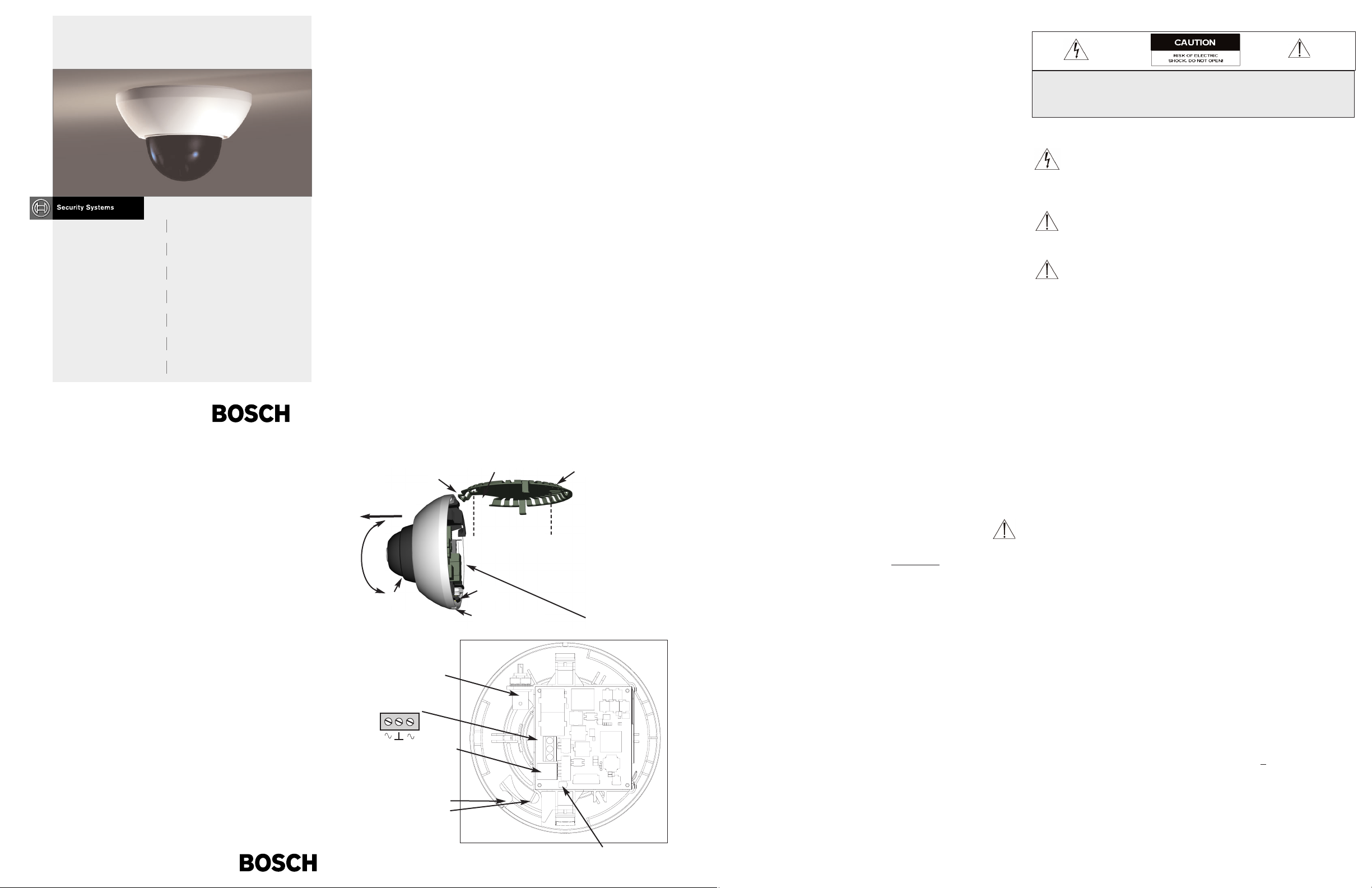
2. INSTALLATION (Refer to Fig. 1)
When you unpack the Flexidome camera, the physical default position of the
camera is that the top of the image is correspondant to the camera ‘Bosch’ logo side.
Before starting the installation, remove the tinted dome by pulling it off and put it in a safe
place to avoid stains and scratches
Mounting the Unit:
The unit has two cable entries for:
• Cables' route is through the surface like false ceiling or in a wall (bottom entry)
• Cables' route is on the surface like concrete wall (side entry)
2.1 Open the mounting plate (1) by pushing the side tab (2b). You can remove the
mounting plate by unhooking from the tab (2a).
2.2 Using the mounting plate (1) as template, drill holes for camera mount and
cables entry as appropriate.
2.3 Connect "power cable*" to the terminal block (POWER); and coaxial cable
(with male BNC connector) to the video connector (BNC).
* For recommended power supply units see “Accessories”.
2.4 Locate cables into the appropriate routing clip (6a bottom entry) (6b side entry).
2.5 Set the Dip switchs (4). (ON/OFF)
(4) LL Line Lock
(3) NC Not Connected
(2) WB White Balance (OFF stores current WB setting)
(1) BLC Back Light Compensation
2.6 V-phase: Potentiometer to adjust the LineLock phase (only if LL is ON).
2.7 Fit the camera onto the mounting plate, by hooking the clip (2a), and then
ensuring the tab (2b) clicks into it's location.
2.8 Adjust the viewing direction of the ball camera (5) and ensure that the picture
display on the monitor is level .
2.9 Click the tinted dome in place and if necessary clean its surface with a soft
cloth.
Note: The image sensors in modern CCD cameras are highly sensitive and require
special care for proper performance and extended lifetime. Please follow the
guidelines to get optimum results of your camera:
■ Do not expose to direct sunlight or bright spotlights in operating and non-
operating conditions.
■ Avoid bright lights in the field of view of the camera.
- These bright lights will cause a "smearing" effect, which is visible as white
lines above and below the highlight.
- Bright lights may cause bleaching of the sensor's color filters. This will be
visible as colored spots in the picture and is irreversible.
3SPECIFICATIONS
Models:
Flexidome 1 - Standard resolution models
Flexidome 11 - High resolution models
FlexiDome 1 FlexiDome 11 Lens TV System
Monochrome
LTC 1311/10 LTC 13 21/10 2 .1 mm f/2.0 CCIR
LTC 1312/10 LTC 1322/10 3 mm f/2.0 CCIR
LTC 1313/10 LTC 1323/10 6 mm f/2.0 CCIR
LTC 1311/20 LTC 1321/20 2.1 mm f/2.0 EIA
LTC 1312/20 LTC 1322/20 3 mm f/2.0 EIA
LTC 1313/20 LTC 1323/20 6 mm f/2.0 EIA
Color
LTC 1411/10 LTC 1421/10 2.1 mm f/2.0 PAL
LTC 1412/10 LTC 1422/10 3 mm f/2.0 PAL
LTC 1413/10 LTC 1423/10 6 mm f/2.0 PAL
LTC 1411/20 LTC 1421/20 2.1 mm f/2.0 NTSC
LTC 1412/20 LTC 1422/20 3 mm f/2.0 NTSC
LTC 1413/20 LTC 1423/20 6 mm f/2.0 NTSC
For all models: Supply voltage: 12 to 28 Vac or Vdc; Power <
2 W.
Weight: 0.4 kg (0.9 lb).
Environmental
Temperature:
Operating: -10
0
C to +45 0C (+14 0F to +113 0F).
Storage: -25 0C to +70 0C (-4 0F to +158 0F).
Humidity: 0% to 93% relative, noncondensing.
Accessories
TC1323 Power Supply: : Input 120 VAC, 60 Hz, Output 24 VAC 60 Hz 10VA
IMPORTANT SAFEGUARDS
1. Read Instructions: All the safety and operating instructions should be read
before the unit is operated.
2. Retain Instructions: The safety and operating instructions should be retained
for future reference.
3. Heed Warnings: All warnings on the unit and in the operating instructions
should be adhered to.
4. Follow Instructions: All operating and use instructions should be followed.
5. Cleaning: Unplug the unit from the outlet before cleaning. Do not use liquid
cleaners or aerosol cleaners. Use a damp cloth for cleaning.
6. Power Sources: This unit should be operated only from the type of power
source indicated on the marking label. If you are not sure of the type of power
supply you plan to use, consult your appliance dealer.
7. Power-Cord Protection: Power-supply cords should be routed so that they are
not likely to be walked on or pinched by items placed upon or against them,
paying particular attention to cords and plugs, convenience receptacles, and
the point where they exit from the appliance.
8. Power Line: An outdoor system should not be located in the vicinity of
overhead power lines or other electric light or power circuits, or where it can
fall into such power lines or circuits.
9. Overloading: Do not overload outlets and extension cords as this can result in
a risk of fire or electric shock.
10. Object and Liquid Entry: Never push objects of any kind into this unit
through openings as they may touch dangerous voltage points or short-out
parts that could result in a fire or electrical shock. Never spill liquid of any
kind on the unit.
11. Servicing: Do not attempt to service this unit yourself as opening or removing
covers may expose you to dangerous voltage or other hazards. Refer all
servicing to qualified service personnel.
12. Damage Requiring Service: Unplug the unit from the outlet and refer
servicing to qualified service personnel under the following conditions.
If liquid has been spilled, or objects have fallen into the unit.
If the unit has been exposed to train or water.
If the unit does not operate normally by following the operating instructions. Adjust
only those controls that are covered by the operating instructions, as an improper
adjustment of other controls may result in damage and will often require extensive
work by a qualified technician to restore the unit to its normal operation.
If the unit has been dropped or the cabinet has been damaged.
When the unit exhibits a distinct change in performance - this indicates a need for
service.
13. Replacement Parts: When replacement parts are required, be sure the service
technician has used replacement parts specified by the manufacturer or have
the same characteristics as the original part. Unauthorized substitutions may
result in fire, electric shock or other hazards.
14. Safety Check: Upon completion of any service or repairs to this unit, ask the
service technician to perform safety checks to determine that the unit is in
proper operating condition.
FCC INFORMATION
This equipment has been tested and found to comply with the limits for a Class B
digital device, pursuant to Part 15 of the FCC Rules. These limits are designed to
provide reasonable protection against harmful interference in a residential
installation. This equipment generates, uses and can radiate radio frequency
energy and, if not installed and used in accordance with the instructions, may
cause harmful interference to radio communications. However, there is no
guarantee that interference will not occur in particular installation. If this
equipment does cause harmful interference to radio or television reception, which
can be determined by turning the equipment off and on, the user is encouraged to
try to correct the interference by one or more of the following measures:
■ Reorient or relocate the receiving antenna.
■ Increase the separation between the equipment and receiver.
■ Connect the equipment into and outlet on a circuit different form that to
which the receiver is connected.
■ Consult the dealer or an experienced radio/ TV technician for help.
Shielded interface cables and A.C. power cord, if any, must be used in order to
comply with emission limits.
Changes or modification not expressly approved by the party responsible for
compliance could void the user's authority to operate the equipment.
SAFETY PRECAUTIONS
This label may appear on the bottom of the unit due to space limitations.
The lightning flash with an arrowhead symbol, within an equilateral
triangle, is intended to alert the user to the presence of un-insulated "
dangerous voltage" within the product's enclosure that may be of
sufficient magnitude to constiuce a risk of electric shock to persons.
The exclamation point within an equilateral triangle is intended to alert
the user to presence of important operating and maintenance (servicing)
instructions in the literature accompanying the appliance.
Attention: Installation should be performed by qualified service personnel
only in accordance with the National Electrical Code or applicable local
codes.
CAUTION: TO REDUCE THE RISK OF ELECTRICAL SHOCK, DO NOT
OPEN COVERS. NO USER SERVICEABLE PARTS INSIDE. REFER
SERVICING TO QUALIFIED SERVICE PERSONNEL.
BNC
1200Horz; 1200Vertical;
360
0
Rotation
Fig. 1
4 DIP
switches
(4) LL
(3) NC
(2) WB
(1) B LC
2a
2b
(6a)
(6b)
3 1
5
V-phase Adjust
Pull Dome cover
to remove
Use a screwdriver to
release clip
Mounting screws
PCB
Power
LTC 131x, LTC 132x
LTC 141x, LTC 142x
3122 165 22501 03-08 © Bosch Security Systems 2003
Data subject to change without notice.
Instructions for use
EN
FlexiDome-I/Flex iDome-II Series Fixed Dome Cameras
Guide de l'utilisateur
FR
FlexiDome-I/Flex iDome-II Series Fixed Dome Cameras
Bedienungsanleitung
DE
FlexiDome-I/Flex iDome-II Series Fixed Dome Cameras
Manual de instrucciones
ES
FlexiDome-I/Flex iDome-II Series Fixed Dome Cameras
Handleiding
NL
FlexiDome-I/Flex iDome-II Series Fixed Dome Cameras
Manuale d'istruzioni
IT
FlexiDome-I/Flex iDome-II Series Fixed Dome Cameras
Manual de instruções
PT
FlexiDome-I/Flex iDome-II Series Fixed Dome Cameras
Page 2

SICHERHEITSVORKENHRUNGEN
Dieses Zeichen kann aus Platzgründen auf der Unterseite des Gerätes angebracht
sein.
Dieses Zeichen weist den Benutzer auf die nicht isolierte Hochspannung
innerhalb der Anlage hin. Es besteht die Gefahr eines Elektroschlages.
Das Ausrufezeichen in dem gleichseitigen Dreieck ist dazu da, den
Benutzer auf wich-tige Inbetriebnahme- und Instandhaltungs-vorschriften
hinzuweisen, die dem Gerät in Form einer Broschüre beigelegt sind.
Achtung!: Die Installation sollte nur von qualifiziertem
Kundendienstpersonal gemäß jeweilig zutreffender Elektrovorschriften ausgeführt werden.
1 STANDARDPAKET ENTHÄLT
- Schraube (für Unterputzmontage), 2 Stück und Dübel (5 mm)
- Dome-Kamera, 1 Stück
- Installationsanleitung, 1 Stück
Nur für die Innenmontage empfohlen
2. I NSTALL AT ION ( S I EH E A B B . 1)
Nach dem Auspacken der Minidome-Kamera ist in der Standardeinstellung des
Kamerabilds im oberen Teil des Bildes das Bosch-Logo zu sehen.
Bevor Sie mit dem Einbau beginnen, die getönte Kuppel durch Ziehen entfernen.
Legen Sie sie an eine sichere Stelle, um Flecken und Kratzer zu vermeiden.
Montage der Kamera:
Fall a: Kabelführung (von unten) unter Montagefläche wie bei abgehängter Decke oder
in einer Wand
Fall b: Kabelführung (seitlich) auf der Oberfläche wie bei einer Betonwand
2.1 Öffnen der Befestigungsplatte (1) durch Drücken der seitlichen Verriegelung
(2b). Zum Entfernen der Befestigungsplatte von seitlicher Verriegelung (2a)
lösen.
2.2 Löcher für die Kamerahalterung und Kabeldurchführung bohren.
Befestigungsplatte (1) als Bohrschablone benutzen.
2.3 "Stromkabel (24 VAC)*" an Klemmenleiste und Koaxialkabel (mit BNCBuchse) an Video-Anschluss (BNC) anschließen.
* Empfohlene Netzteile können Sie dem Abschnitt "Zubehör" entnehmen.
2.4 Kabel in die vorgesehene Kabelhalterung legen (6a Kabelführung von unten)
(6b seitliche Kabelführung).
2.5 Dipschalter (4) einstellen. (EIN/AUS)
(4) LL Line Lock
(3) NC Nicht angeschlossen
(2) WB Weißabgleich (AUS speichert aktuellen Weißabgleich)
(1) BLC Gegenlichtkompensation
2.6 V-Phase Potentiometer zur Einstellung von LineLock-Phase (nur bei
eingeschalteter LL (ON))
2.7 Kamera durch Einrasten des Clips (2a) auf der Befestigungsplatte montieren.
Sicherstellen, dass die seitliche Verriegelung (2b) an der dafür vorgesehenen
Stelle einrastet.
2.8 Den Sichtbereich der Kugelkamera (5) einstellen und sicherstellen, dass das
auf dem Bildschirm wiedergegebene Bild gerade ist.
2.9 Die getönte Kuppel wieder aufsetzen und darauf achten, daß sie einrastet. Falls
erforderlich, die Oberfläche reinigen.
Achtung: Die Bildsensoren in modernen CCD-Kameras sind hochempfindlich und
erfordern für eine optimale Leistung und erhöhte Lebensdauer besondere Pflege. Um mit
Ihrer Kamera optimale Ergebnisse zu erzielen, beachten Sie bitte folgende Hinweise:
■ Kamera weder im Betrieb noch bei Nichtbenutzung direkter Sonneneinstrahlung
oder grellem Licht aussetzen.
■ Helles Licht im Blickfeld der Kamera vermeiden.
- Helles Licht verursacht „Verwischungen”, die als weiße Linien über oder unter
dem hellen Bereich erscheinen.
- Helles Licht kann zum Ausbleichen der Farbfilter des Sensors führen. Dies hat
farbige Punkte auf dem Bild zur Folge und ist irreversibel.
3SPEZIFIKATIONEN
Modelle
FlexiDome 1: Standardauflösung
FlexiDome 11: Hohe Auflösung
FlexiDome 1 FlexiDome 11 Objektiv TV-System
Schwarzweiß
LTC 1311/10 LTC 13 21/10 2 .1 m m f/2.0 CCIR
LTC 1312/10 LTC 1322/10 3 mm f/2.0 CC IR
LTC 1313/10 LTC 1323/10 6 mm f/2.0 CCIR
LTC 1311/20 LTC 1321/20 2.1 mm f/2.0 EIA
LTC 1312/20 LTC 1322/20 3 mm f/2.0 EIA
LTC 1313/20 LTC 1323/20 6 mm f/2.0 EIA
Farbe
LTC 1411/10 LTC 14 21/10 2.1 m m f/2.0 PAL
LTC 1412/10 LTC 1422/10 3 mm f/2.0 PAL
LTC 1413/10 LTC 1423/10 6 mm f/2.0 PAL
LTC 1411/20 LTC 1421/20 2.1 mm f/2.0 NTSC
LTC 1412/20 LTC 1422/20 3 mm f/2.0 NTSC
LTC 1413/20 LTC 1423/20 6 mm f/2.0 NTSC
Für alle Modelle: Stomversorgung 12 bis 28VAC oder VDC; Stromverbrauch < 2 W.
Gewicht: 0,4 kg
Umgebungstemperatur:
Betrieb: -10
0
C bis +45 0C
Lagerung: -25
0
C bis +70 0C
Feuchtigkeit: 0% bis 93% relative Luftfeuchtigkeit, nicht kondensierend.
Zubehör
TC1323 Netzteil: Eingangsspannung 120 VAC, 60 Hz, Ausgangsspannung 24 VAC
60 Hz 10VA
TC220PSX-24 Netzteil: Eingangsspannung 220-240 VAC, 50/60 Hz
Ausgangsspannung 24 VAC 50/60 Hz 20VA
SECURITE
Cet étiquette peut apparaître en dessous de l’appareil dû aux limitations
d’espace.
L’éclair fléché dans un triangle équilatéral avertit l’utilisateur de la présence
d’une haute tension non isolée à l’intérieur de l’appareil. Elle peut être
d’une magnitude suffisante pour constituer un risque d’electrocution.
Le point d’exclamation à l’intérieur d’un triangle équilatéral avertit
l’utilisateur de la présence d’instructions importantes d’utilisation et de
maintenance dans la documentation accompagnant l’appareil.
Attention: L’installation doit être effectuée uniquement par du personnel de service
qualifié conformément à la réglementation du Code Electrique National ou à la
réglementation locale.
1 CONTENU DU KIT STANDARD
- 2 vis (pour encastrement) et fiches (5 mm)
- 1 caméra dôme
- 1 manuel d’instructions d'installation
Recommandé uniquement pour les utilisations intérieures
2. I NSTALL AT ION ( C F. F I G . 1)
Une fois la caméra minidôme déballée, la partie supérieure de l’image filmée est
orientée par défaut vers le logo Bosch.
Avant de l'installer, retirez le dôme teinté en tirant dessus et rangez-le dans un
endroit sûr pour éviter qu'il soit tâché ou rayé.
Montage de l'unité :
Cas a : les câbles sont encastrés, sous un faux plafond ou dans un mur, par exemple
(entrée par le bas).
Cas b : les câbles sont fixés, sur un mur en béton par exemple (entrée latérale).
2.1 Ouvrez la plaque de montage (1) en poussant la languette latérale (2b). Vous
pouvez retirer la plaque en décrochant la languette (2a).
2.2 Utilisez la plaque de montage (1) comme gabarit et percez des trous pour le
montage de la caméra et le passage des câbles.
2.3 Branchez le « câble d'alimentation* » au bloc de raccordement
(ALIMENTATION) et le câble coaxial (doté d'un connecteur BNC mâle) au
connecteur vidéo (BNC).
* Pour de plus amples informations sur les blocs d'alimentation conseillés,
reportez-vous à la section « Accessoires ».
2.4 Faites passer les câbles dans le clip d'acheminement approprié (6a entrée par
le bas) (6b entrée latérale).
2.5 Réglez les micro-interrupteurs (4). (MARCHE/ARRÊT)
(4) LL Verrouillage secteur/ligne
(3) NC Non connecté
(2) WB Équilibrage des blancs (l'option OFF permet de stocker le paramètre
WB courant)
(1) BLC Compensation de contre-jour
2.6 Phase V : potentiomètre permettant de régler la phase de verrouillage
secteur/ligne (uniquement si le micro-interrupteur LL est défini sur ON).
2.7 Installez la caméra sur la plaque de montage, en attachant le clip (2a), puis en
vous assurant que la languette latérale (2b) est en place.
2.8 Réglez la direction de la boule de la caméra (5) et assurez-vous que l'image
affichée sur l'écran du moniteur est nette.
2.9 Mettez le dôme teinté en place et si nécessaire, nettoyez-en la surface.
Remarque: les capteurs d’image des caméras CCD modernes sont très sensibles
et nécessitent une attention toute particulière afin que leurs performances soient
correctes et leur longévité étendue. Pour obtenir des résultats optimaux, veillez à
respecter les instructions suivantes :
■ N’exposez pas la caméra à la lumière directe du soleil ou à des projecteurs
intenses pendant et hors fonctionnement.
■ Evitez les sources d’éclairage intensif dans la zone de vue de la caméra.
- En effet, ces lumières peuvent entraîner un effet de rémanence, visible sous la
forme de lignes blanches au-dessus et sous l’éclairage.
- Des lumières intenses peuvent entraîner la décoloration des filtres de couleur
des capteurs. Ceci se matérialise par des points colorés apparaissant sur
l’image. Cet effet est irréversible.
3 SPÉCIFICATIONS
Modèles
FlexiDome 1: Résolution standard
FlexiDome 11: Haute résolution
FlexiDome 1 FlexiDome 11 Objectif Système TV
Monochromes
LTC 1311/10 LTC 1321/10 2.1 mm f/2.0 CCIR
LTC 1312/10 LTC 1322/10 3 mm f/2.0 CCIR
LTC 1313/10 LTC 1323/10 6 mm f/2.0 CCIR
LTC 1311/20 LTC 1321/20 2.1 mm f/2.0 EIA
LTC 1312/20 LTC 1322/20 3 mm f/2.0 EIA
LTC 1313/20 LTC 1323/20 6 mm f/2.0 EIA
Couleur
LTC 1411/10 LTC 1421/10 2.1 mm f/2.0 PAL
LTC 1412/10 LTC 1422/10 3 mm f/2.0 PAL
LTC 1413/10 LTC 1423/10 6 mm f/2.0 PAL
LTC 1411/20 LTC 1421/20 2.1 mm f/2.0 NTSC
LTC 1412/20 LTC 1422/20 3 mm f/2.0 NTSC
LTC 1413/20 LTC 1423/20 6 mm f/2.0 NTSC
Pour les modèles : Tension; 12 à 28 V c.a. ou c.c.: Puissance < 2 W
Poids : 0,4 kg
Spécifications environnementales
Températures :
En fonctionnement : -10
0
C à +45 0C
Stockage : -25 0C à +70 0C
Humidité : Entre 0% et 93% d'humidité relative non condensée
Accessoires
Alimentation TC1323 : Entrée de 120 Vca, 60 Hz, sortie de 24 Vca, 60 Hz, 10 VA
Alimentation TC220PSX-24 : Entrée de 220-240 Vca, 50/60 Hz
Sortie de 24 Vca, 50/60 Hz, 20 VA
ATTENTION
RISQUE D'ÉLECTROCUTION.
NE PAS OUVRIR
DANGER: POUR ÉVITER TOUT RISQUE D’ÉLECTROCUTION, NE PAS
OUVRIR LE BOÎTIER. IL N’Y A PAS DE PIÈCES REMPLAÇABLES À
L’INTÉRIEUR. POUR TOUTE RÉVISION, S’ADRESSER À UN TECHNICIEN
SPÉCIALISÉ.
VORSICHT
RISICO EINES ELEKTRISCHEN
SCHLAGES NICHT OFFNEN!
WARNUNG: VERHINDERN SIE EINEN MÖGLICHEN ELEKTROSCHLAG,
INDEM SIE DIE ABDECKUNG NICHT ENTFERNEN. WENDEN SIE SICH
BEI DER WARTUNG AN DAFÜR QUALIFIZIERTES PERSONAL.
BNC
Horizontal 1200; Vertical
120
0
, Rotation à 360
0
Fig. 1
4 Micro-
interrupteur
(4) LL
(3) NC
(2) WB
(1) B LC
2a
2b
(6a)
(6b)
3 1
5
Phase V
Tirez sur
l’enveloppe du
dôme pour la
retirer.
Utilisez un tournevis
pour libérer le clip.
Vis de montage
PCB
Alimentation
BNC
1200horizontal; 120
0
vertikal; 3600Drehung
Abb. 1
4 DIP
(4) LL
(3) NC
(2) WB
(1) B LC
2a
2b
(6a)
(6b)
3 1
5
V-Phase
Ziehen um Dome-
Abdeckung zu
entfernen
Zum Lösen des Clips
Schraubendreher verwenden
Befestigungsschrauben
PCB
Strom
Page 3

VEILIGHEIDSMAATREGELEN
Dit etiket kan zich, indien er elders op het apparaat geen plaats is, op de
onderzijde van het apparaat bevinden.
Een bliksemflits in een gelijkbenige driehoek attendeert de gebruiker op
de aanwezigheid van ongeisoleerde gevaarlijke spanningen in het
apparaat. Deze spanningen zijn voldoende groot om een risico voor een
elektrische schok te vormen.
Een uitroepteken in een gelijkbenige driehoek attendeert de gebruiker op
de aanwezigheid van belangrijke bedienings- en onderhoudsinstructies in
de bij het apparaat behorende documentatie.
Attentie: Het apparaat mag alleen door kundig service personeel worden
geinstalleerd. De installatie dient in overeenstemming met de nationale
elektrische richtlijnen of de van toepassing zijnde lokale richtlijnen te
worden uitgevoerd.
1 STANDAARDPAKKET bevat
- 2 schroeven (voor verzonken montage) en plugjes (5 mm)
- 1 dome-camera
- 1 installatiehandleiding
Alleen aanbevolen voor toepassing binnen gebouwen
2. INSTALLATIE (zie afb. 1)
Wanneer u de minidome-camera uitpakt, is de standaard weergavepositie van het
camerabeeld met de bovenkant bij het Bosch-logo.
Verwijder de getinte dome voordat u de camera gaat installeren. Leg deze dome op
een plaats waar hij niet kan worden vervuild of bekrast.
Camera monteren:
Scenario a: Bekabeling in een muur of boven hangend plafond (kabelinvoer onderkant)
scenario b: Bekabeling op ondergrond, b.v. betonnen wand (kabelinvoer zijkant)
2.1 Verwijder de montageplaat (1) door het nokje (2b) in te drukken. U kunt de
montageplaat losnemen door die uit de vergrendeling (2a) te haken.
2.2 Boor gaatjes die nodig zijn voor de camera en de kabelinvoer. Gebruik de
montageplaat (1) als sjabloon.
2.3 Sluit de voedingskabel (24 V AC)* aan op de strip met aansluitschroeven.
Sluit de coaxkabel (met een 'male' BNC-connector) aan op de videoconnector
(BNC).
* Raadpleeg "Accessoires" voor de aanbevolen voedingseenheden.
2.4 Haal de kabels door de juiste geleidingsclip (6a kabelinvoer onder) (6b
kabelinvoer opzij).
2.5 Stel de DIP-switches (4) in (ON/OFF)
(4) LL Synchronisatie op fase van voedingsspanning (Line Lock)
(3) NC Niet in gebruik
(2) WB Witbalans (OFF slaat huidige WB-instelling op)
(1) BLC Tegenlichtcompensatie
2.6 V-fase : Potentiometer voor fase van voedingsspanning (alleen als LL op ON
staat).
2.7 Plaats de camera op de montageplaat door de clip (2a) vast te haken en zorg
dat het nokje (2b) vastklikt.
2.8 Pas de kijkrichting van de camera (5) aan en zorg dat het camerabeeld op de
monitor recht staat.
2.9 Klik de getinte dome vast en maak indien nodig de buitenkant schoon.
Opmerking: De beeldsensors in moderne CCD-camera's zijn uiterst gevoelig.
Daarom is voor een juiste werking en een lange levensduur een zorgvuldige
behandeling nodig. Houd u aan de volgende richtlijnen om te zorgen dat uw camera
de optimale prestaties levert:
■ Zorg dat het objectief nooit recht in zonlicht of een felle spot kijkt.
■ Vermijd dat felle lampen in het gezichtsveld van de cameralens schijnen.
- Dergelijke felle lichtbronnen leiden tot "smearing", een effect dat zichtbaar
wordt als witte strepen boven en onder in het beeld.
- Felle lampen kunnen de kleurenfilters van de sensor aantasten. Dit leidt tot
gekleurde vlekken in het beeld en is onherstelbaar.
3 SPECIFICATIES
Modellen
FlexiDome 1: Standaard resolutie
FlexiDome 11: Hoge Resolutie
FlexiDome 1 FlexiDome 11 Lens TV-norm
Monochroom
LTC 1311/10 LTC 1321/10 2.1 mm f/2.0 CCIR
LTC 1312/10 LTC 1322/10 3 mm f/2.0 CCIR
LTC 1313/10 LTC 1323/10 6 mm f/2.0 CCIR
LTC 1311/20 LTC 1321/20 2.1 mm f/2.0 EIA
LTC 1312/20 LTC 1322/20 3 mm f/2.0 EIA
LTC 1313/20 LTC 1323/20 6 mm f/2.0 EIA
Kleur
LTC 1411/10 LTC 1421/10 2.1 mm f/2.0 PAL
LTC 1412/10 LTC 1422/10 3 mm f/2.0 PAL
LTC 1413/10 LTC 1423/10 6 mm f/2.0 PAL
LTC 1411/20 LTC 1421/20 2.1 mm f/2.0 NTSC
LTC 1412/20 LTC 1422/20 3 mm f/2.0 NTSC
LTC 1413/20 LTC 1423/20 6 mm f/2.0 NTSC
Voor alle modellen: Voedingsspanning 12 - 28 V AC of V DC;
Opgenomen vermogen <2 W.
Gewicht: 0,4 kg.
Omgevingscondities
Temperatuur:
In gebruik: -10
0
C tot +450C.
Buiten gebruik: -250C tot +700C.
Relatieve luchtvochtigheidsgraad: 0% tot 93%, zonder condens.
Accessoires
TC1323 voedingseenheid: ingangsspanning 120 V AC, 60 Hz, uitgangsspanning
24 V AC, 60 Hz, 10 VA
TC220PSX-24 voedingseenheid: ingangsspanning 220-240 V AC, 50/60 Hz,
uitgangsspanning 24 V AC, 50/60 Hz, 20 VA
PRECAUCIONES DE SEGURIDAD
Debido a limitaciones de espacio, esta etiqueta puede aparecer en la parte inferior
de la unidad.
El símbolo representado por un relámpago con punta de flecha dentro de
un triángulo equilátero, se muestra con el objetivo de alertar al usuario que
existen "voltages peligrosos" sin aislamiento, dentro de la cubierta de la
unidad. Dichos voltages pueden ser de tal magnitud que constituyen un
riesgo de choque eléctrico a personas.
El símbolo de exclamación dentro de un triángulo equilátero, se muestra
con el objetivo de alertar al ususario de que instrucciones de operación y
mantenimiento importantes acompañan al equipo
Atención: La instalación de este equipo debe ser realizada por personal
capacitado, solo en acuerdo, y en cumplimiento de normas del "National
Electric Code" (Código Eléctrico Nacional) ó las normas del Gobierno
Nacional Local
1 PAQUETE ESTÁNDAR, incluye
- 2 tornillos (para montaje empotrado) y clavijas (5 mm)
- 1 cámara burbuja
- Instrucciones de instalación
Recomendada para aplicaciones interiores únicamente
2. INSTALACIÓN (CONSULTE LA FIG. 1)
Cuando se extrae la cámara MiniDome de su embalaje, la posición por defecto de la
imagen de la cámara es con la parte superior de la imagen en el lado del logotipo de Bosch.
Antes de iniciar la instalación, retire la burbuja tintada tirando de ella hacia fuera y
deposítela en un lugar seguro para evitar que se manche o se arañe.
Montaje de la unidad:
caso a: Los cables se encaminan por una superficie como un falso techo o por la pared
(entrada inferior)
caso b: Los cables se encaminan por una superficie como un muro de hormigón
(entrada lateral)
2.1 Abra la placa de montaje (1) empujando la lengüeta lateral (2b). Puede retirar
la placa de montaje desenganchándola de la lengüeta (2a).
2.2 Utilizando la placa de montaje (1) como plantilla, taladre los orificios para el
soporte de la cámara y la entrada de cables según convenga.
2.3 Conecte el "cable de alimentación (24 Vca)*" al bloque de terminal, y el cable
coaxial (con conector BNC macho) al conector de vídeo (BNC).
* Para saber cuáles son las unidades de fuente de alimentación recomendadas,
consulte "Accesorios".
2.4 Sitúe los cables en el clip de encaminamiento adecuado (6a entrada inferior)
(6b entrada lateral).
2.5 Ajuste los conmutadores DIP (4). ON/OFF (activado/desactivado)
(4) LL Sincronización por línea
(3) NC Sin conectar
(2) WB Compensación de blanco (OFF almacena la WB actual)
(1) BLC Compensación de contraluz
2.6 Fase V : Potenciómetro para ajustar la fase de sincronización por línea (sólo si
LL está activado).
2.7 Coloque la cámara sobre la placa de montaje enganchando el clip (2a) y
asegúrese de que la lengüeta (2b) encaja perfectamente en su posición con un
sonido de "clic".
2.8 Ajuste la dirección de visualización de la cámara burbuja (5) y asegúrese de
que la imagen que aparece en el monitor es estable.
2.9 Encaje la burbuja tintada en su sitio y, si resulta necesario, limpie su
superficie.
Nota: los sensores de imágenes de las cámaras CCD modernas son muy
sensibles y exigen un cuidado especial para conseguir un correcto rendimiento y
una vida útil prolongada. Siga estas directrices para obtener resultados óptimos
con su cámara:
■ No la exponga a la luz solar directa ni a focos potentes cuando la utilice o
mientras esté guardada.
■ Evite la utilización de luces brillantes en el campo de visión de la cámara.
- Estas luces provocarán un efecto de "manchas" en forma de líneas blancas
encima y debajo del punto brillante.
- Las luces brillantes pueden hacer que los filtros de color del sensor se
blanqueen. Este efecto aparecerá como puntos de color en la fotografía y no
puede corregirse.
3 ESPECIFICACIONES
Modelos
FlexiDome 1: Resolución estándar
FlexiDome 11: Alta resolución
FlexiDome 1 FlexiDome 11 Lente Sistema de TV
Blanco y negro
LTC 1311/10 LTC 1321/10 2.1 mm f/2.0 CCIR
LTC 1312/10 LTC 1322/10 3 mm f/2.0 CCIR
LTC 1313/10 LTC 1323/10 6 mm f/2.0 CCIR
LTC 1311/20 LTC 1321/20 2.1 mm f/2.0 EIA
LTC 1312/20 LTC 1322/20 3 mm f/2.0 EIA
LTC 1313/20 LTC 1323/20 6 mm f/2.0 EIA
Color
LTC 1411/10 LTC 1421/10 2.1 mm f/2.0 PAL
LTC 1412/10 LTC 1422/10 3 mm f/2.0 PAL
LTC 1413/10 LTC 1423/10 6 mm f/2.0 PAL
LTC 1411/20 LTC 1421/20 2.1 mm f/2.0 NTSC
LTC 1412/20 LTC 1422/20 3 mm f/2.0 NTSC
LTC 1413/20 LTC 1423/20 6 mm f/2.0 NTSC
Para todos los modelos: Tensión de alimentación12 a 28Vca o Vcc; Potencia < 2 W.
Peso: 0,4 kg
Entorno
Temperatura:
Funcionamiento: -10 a +45 0C
Almacenamiento: -25 a +70 0C
Humedad: 0 a 93% relativa, sin condensación.
Accesorios
Fuente de alimentación de TC1323: Entrada de 120 Vca, 60 Hz, salida de 24
Vca, 60 Hz, 10 VA
Fuente de alimentación de TC220PSX-24: Entrada de 220-240 Vca, 50/60 Hz,
salida de 24 Vca, 50/60 Hz, 20 VA
PRECAUCION
RIESGO DE CHOQUE
ELECTRICO INO ABRIR1!
PRECAUCION: PARA REDUCIR EL RIESGO DE CHOQUE ELÉCTRICO,
FAVOR NO ABRIR LA CUBIERTA. ESTE EQUIPO NO CONSTA DE PIEZAS
O PARTES QUE REQUIEREN SERVICIO O MANTENIMIENTO. PARA
REPARACIONES FAVOR REFERIRSE A UN TÉCNICO CALIFICADO.
VOORZICHTIG
RISICO VAN ELEKTRISCHE
SCHOK NIET OPENEN
VOORZICHTIG: OM HET RISICO VAN EEN ELEKTRISCHE SCHOK TE
VOORKOMEN MAG HET APPARAAT NIET WORDEN GEOPEND. DIT
APPARAAT BEVAT GEEN DOOR DE GEBRUIKER TE ONDERHOUDEN
ONDERDELEN. LAAT SERVICE EN ONDERHOUD UITVOEREN DOOR
GEKWALIFICEERD PERSONEEL.
BNC
1200horizontal; 120
0
vertical; giro de 360
0
fig. 1
4 DIP
(4) LL
(3) NC
(2) WB
(1) B LC
2a
2b
(6a)
(6b)
3 1
5
Fase V
Tire de la
cubierta de la
burbuja para
retirarla
Utilice un destornillador
para quitar el clip
Tornillos de montaje
PCB
corriente
BNC
1200hor.; 1200vert.;
3600rotatie
fig. 1
4 DIP
(4) LL
(3) NC
(2) WB
(1) B LC
2a
2b
(6a)
(6b)
3 1
5
V-fase
Trek aan
domekapje om
los te maken
Maak de clip los met een
schroevendraaier
Bevestigingsschroeven
PCB
Voeding
Page 4

PRECAUZIONI PER LA SICUREZZA
Per motivi di spazio, questa etichetta potrebbe essere applicata nella parte inferiore
dell’unità.
Il simbolo di un fulmine a freccia, racchiuso in un triangolo equilatero,
avverte l’utente della presenza di “tensioni pericolose” non isolate
all’interno del prodotto, sufficienti per costituire un possibile rischio di
folgorazione per le persone.
Il punto esclamativo racchiuso in un triangolo equilatero avverte l’untente
della presenza di importanti istruzioni per l’uso o per la manutenzione
(assistenza) nella documentazione allegata al prodotto.
Attenzione: L’installazione dovrebbe essere effettuate da personale
qualificato esclusivamente in accordo con il National Electrical Code o
con le normative in vigore localmente.
1 LA CONFEZIONE STANDARD include
- 2 viti (per montaggio ad incasso) e tasselli (5 mm)
- 1 unità telecamera Dome
- 1 Istruzioni per l'installazione:
Raccomandato solo per applicazioni per interni
2. INSTALLAZIONE (VEDI FIG. 1)
L'orientamento predefinito all'acquisto dell'immagine telecamera è con la parte
superiore dal lato del logo Bosch.
Prima di procedere con l'installazione, rimuovere la cupola colorata e collocarla in un
luogo sicuro per evitare di graffiarla o sporcarla
Montaggio dell'unità
caso a: il cablaggio passa attraverso una superficie, quale una controsoffittatura o
un falso soffitto o una parete (ingresso inferiore)
caso b: il cablaggio scorre lungo superficie, ad esempio una parete in cemento
(ingresso laterale)
2.1 Aprire la piastra di montaggio (1) premendo sulla linguetta laterale (2b). Per
rimuovere la piastra di montaggio sganciarla dalla linguetta (2a).
2.2 Eseguire i fori per telecamera e ingresso del cablaggio, utilizzando la piastra di
montaggio come dima di riferimento (1).
2.3 Collegare il "cavo d'alimentazione (24Vcc)*" al blocco terminali ed il cavo
coassiale (con BNC maschio) al connettore video (BNC).
* Per informazioni sugli alimentatori raccomandati, consultare "Accessori".
2.4 Inserire i cavi nella relativa clip passacavo (6a ingresso inferiore) (6b ingresso
laterale).
2.5 Impostare i Dip switch (4). (ON/OFF)
(4) LL Line Lock
(3) NC Non collegato
(2) WB Bilanciamento del bianco (OFF memorizza l'impostazione
corrente)
(1) BLC Compensazione del controluce
2.6 Fase-V : potenziometro per regolare la fase LineLock (solo se LL è ON).
2.7 Installare la telecamera sulla piastra di montaggio, fissando la clip (2a) ed
assicurandosi che la linguette (2b) scatti in posizione.
2.8 Regolare l'inquadratura della telecamera mediante il giunto a sfera (5)
verificando il risultato sul monitor.
2.9 Installare la cupola colorata in sede e se necessario pulirne la superficie.
Nota: : I sensori immagine delle telecamere di moderna concezione sono
estremamente sensibili e richiedono attenzioni particolari per mantenerne inalterate
le prestazioni e la durata nel tempo. Seguire questi consigli per ottenere risultati
ottimali nell'uso della telecamera:
■ Non esporre la telecamera alla luce solare diretta o a punti luce di forte
intensità, sia durante l'utilizzo sia quando non viene utilizzata.
■ Evitare la presenza di sorgenti luminose di forte intensità all'interno del campo
di visuale della telecamera.
- Le sorgenti luminose di forte intensità possono causare l'effetto "alone",
visibile in forma di linee bianche sopra e sotto le alteluci.
- Le sorgenti luminose di forte intensità possono causare il deterioramento dei
filtri colore del sensore. Questo problema si manifesta sotto forma di macchie
colorate nell'immagine ed è un danno irreversibile.
3 SPECIFICHE
Modelli
FlexiDome 1: Risoluzione standard
FlexiDome 11: Alta risoluzione
FlexiDome 1 FlexiDome 11 Ottica Sistema TV
Monocromatico
LTC 1311/10 LTC 1321/10 2.1 mm f/2.0 CCIR
LTC 1312/10 LTC 1322/10 3 mm f/2.0 CCIR
LTC 1313/10 LTC 1323/10 6 mm f/2.0 CCIR
LTC 1311/20 LTC 1321/20 2.1 mm f/2.0 EIA
LTC 1312/20 LTC 1322/20 3 mm f/2.0 EIA
LTC 1313/20 LTC 1323/20 6 mm f/2.0 EIA
Colore
LTC 1411/10 LTC 14 21/10 2.1 m m f/2.0 PAL
LTC 1412/10 LTC 1422/10 3 mm f/2.0 PAL
LTC 1413/10 LTC 1423/10 6 mm f/2.0 PAL
LTC 1411/20 LTC 1421/20 2.1 mm f/2.0 NTSC
LTC 1412/20 LTC 1422/20 3 mm f/2.0 NTSC
LTC 1413/20 LTC 1423/20 6 mm f/2.0 NTSC
Per tutti i modelli: Alimentazione da 12 a 28Vca o Vcc; Consumo < 2 W.
Peso: 0,4 kg.
Ambientali
Temperatura:
In funzione: da -10 0C a +45 0C.
In stoccaggio: da -25 0C a +70 0C.
Umidità: da 0% a 93% relativa, non condensante.
Accessori
Alimentatore TC1323: : Ingresso 120 VCA, 60 Hz, Uscita 24 VCA 60 Hz 10VA
Alimentatore TC220PSX-24: Ingresso 220-240 VCA, 50/60 Hz,
Uscita 24 VCA 50/60 Hz 20VA
INSTRUÇÕES DE SEGURANÇA
Este aviso pode estar localizado na parte inferior do aparelho devido a limitações
de espaço.
O símbolo do relâmpago contido num triângulo equilátero tem como
objectivo alertar o utilizador para a presença de de uma “tensão perigosa”
não isolada, no interior do aparelho e que pode constituir perigo para a
saúde do utilizador.
O ponto de exclamação contido num triângulo equilátero tem o objectivo
de alertar o utilizador para a presença de instruções de manutenção
(serviço) importantes, incluídas na literatura que acompanha o aparelho.
Atenção: A instalação deve ser executada por pessoal devidamente
qualificado de acordo com o regulamento eléctrico ou quaisquer outros
regulamentos aplicáveis, em vigor no país.
1 PACOTE STANDARD incluído
- Parafuso (para montagem à face) x 2 peças e fichas (5 mm)
- Câmara Dome x 1
- Instruções de instalação x 1
Aconselhado apenas para utilização em interiores
2. INSTALAÇÃO (Consulte a Fig. 1)
Quando desembalar a mini-câmara Dome, tenha em atenção que a posição predefinida
da imagem da câmara é com a parte superior da imagem ao lado do logótipo da 'Bosch'.
Antes de começar a instalação, retire a cúpula colorida puxando-a para fora e
colocando-a num local seguro para evitar o aparecimento de manchas e riscos
Montar a unidade:
caso a: A passagem dos cabos é efectuada através da superfície como num tecto
falso ou parede (entrada inferior)
caso b: A passagem dos cabos é efectuada à superfície como numa parede de
cimento (entrada lateral)
2.1 Abra a placa de fixação (1) empurrando a patilha lateral (2b). Pode retirar a
placa de fixação desprendendo-a da patilha (2a).
2.2 Faça furos para montagem da câmara e entrada dos cabos como for
adequado, utilizando a placa de fixação (1) como modelo.
2.3 Ligue o "cabo de alimentação (24 Vac)*" à chapa de terminais; e o cabo
coaxial (com o conector BNC macho) ao conector de vídeo (BNC).
* Para saber quais as fontes de alimentação recomendadas, consulte
"Acessórios".
2.4 Faça passar os cabos pela passadeira adequada (entrada inferior 6a) (entrada
lateral 6b).
2.5 Ajuste os interruptores Dip (4). (ACTIVADO/DESACTIVADO)
(4) LL Bloqueio de linha
(3) NC Não ligado
(2) WB Equilíbrio de branco (DESACTIVADO memoriza o equilíbrio de
branco)
(1) BLC Compensação da luz de fundo
2.6 Fase V : Potenciómetro para ajustar a fase de bloqueio de linha (apenas se LL
estiver ACTIVADO).
2.7 Instale a câmara na placa de fixação, prendendo o grampo (2a) e verificando
se a patilha (2b) encaixa na devida posição.
2.8 Ajuste a direcção de observação da câmara (5) e verifique se a imagem do
monitor está nivelada .
2.9 Encaixe a cúpula colorida na devida posição e, se necessário, limpe a respectiva
superfície.
Nota: Os sensores de imagem existentes nas modernas câmaras CCD são
extremamente sensíveis e requerem um cuidado especial para se obter um
desempenho adequado e uma vida útil alargada dos mesmos. Siga estas directrizes
para obter os melhores resultados com a câmara:
■ Não a exponha à luz solar directa nem a projectores de luz forte, tanto em
condições de funcionamento como de inactividade.
■ Afaste as luzes fortes do campo de visão da câmara.
- Estas luzes fortes provocam um efeito de "mancha", que se torna visível sob a
forma de linhas brancas por cima e por baixo da luz.
- As luzes fortes podem provocar o branqueamento dos filtros de cor dos
sensores, resultando em manchas coloridas na imagem. Este efeito é
irreversível.
3 ESPECIFICAÇÕES
Modelos
FlexiDome 1: Resolução Standard
FlexiDome 11: Alta Resolução
FlexiDome 1 FlexiDome 11 Lente Sistema de TV
Monocromático
LTC 1311/10 LTC 1321/10 2.1 mm f/2.0 CCIR
LTC 1312/10 LTC 1322/10 3 mm f/2.0 CCIR
LTC 1313/10 LTC 1323/10 6 mm f/2.0 CCIR
LTC 1311/20 LTC 1321/20 2.1 mm f/2.0 EIA
LTC 1312/20 LTC 1322/20 3 mm f/2.0 EIA
LTC 1313/20 LTC 1323/20 6 mm f/2.0 EIA
A cores
LTC 1411/10 LTC 14 21/10 2.1 m m f/2.0 PAL
LTC 1412/10 LTC 1422/10 3 mm f/2.0 PAL
LTC 1413/10 LTC 1423/10 6 mm f/2.0 PAL
LTC 1411/20 LTC 1421/20 2.1 mm f/2.0 NTSC
LTC 1412/20 LTC 1422/20 3 mm f/2.0 NTSC
LTC 1413/20 LTC 1423/20 6 mm f/2.0 NTSC
Para todos os modelos: Tensão de alimentação12 a 28Vac ; Alimentação < 2 W.
Peso: 0,4 kg (0.9 lb).
Temperatura ambiente:
Funcionamento: -10 0C a +45 0C (+14 0F a +113 0F).
Armazenamento: -25 0C a +70 0C (-4 0F a +158 0F).
Humidade: 0% a 93% relativa, sem condensação.
Acessórios
Fonte de alimentação do TC1323: : Entrada 120 VAC, 60 Hz, Saída 24 VAC 60
Hz 10VA
Fonte de alimentação do 0TC220PSX-24: Entrada 220-240 VAC, 50/60 Hz,
Saída 24 VAC 50/60 Hz 20VA
AVVERTENZA
RISCHIO DI FOLGORAZIONE
NON APRIRE!
AVVERTENZA: PER RIDURRE I RISCHI DI FOLGORAZIONE, NON APRIRE
LE COPERTURE. ALL’INTERNO NON VI SONO COMPONENTI RIPARABILI
DALL’UTENTE. AFFIDARSI PER L’ASSISTENZA A PERSONALE
QUALIFICATO
CUIDADO: DE MODO A REDUZIR O RISCO DE CHOQUE ELÉCTRICO,
NÃO ABRA O APARELHO, NO INTERIOR NÃO EXISTEM PEÇAS DE
SUBSTITUIÇÃO PELO CLIENTE, DEVE PARA ISSO DIRIGIR-SE AOS
TÉCNICOS DE ASSINTÊNCIA DEVIDAMENTE QUALIFICADOS.
BNC
1200Orizz.; 120
0
Verticale; 3600Rotazione
fig. 1
4 DIP
(4) LL
(3) NC
(2) WB
(1) B LC
2a
2b
(6a)
(6b)
3 1
5
Faso-V
Tirare il coperchio
della cupola per
rimuoverlo
Utilizzare un cacciavite per
rilasciare la clip
Viti di montaggio
PCB
Alimentazione
BNC
1200na horizontal;
1200na vertical;
rotação de 360
0
fig. 1
4 DIP
(4) LL
(3) NC
(2) WB
(1) B LC
2a
2b
(6a)
(6b)
3 1
5
Fase V
Para retirar a
tampa da cúpula,
puxe-a
Utilize uma chave de
parafusos para soltar o
grampo
Parafusos de
fixação
PCB
Alimentação
CUIDADO
RISCO DE CHOQUE
ELÉCTRICO. NÃO ABRA!
 Loading...