

Page 1
Bosch Prosound 12" Ceiling Speaker
Installation and User Instructions
LC2 -PC60G6 -12en
Page 2

Table of Contents
Table of Contents ............................................................................................................. TOC
Safety First ....................................................................................................................... TOC
Packing List ............................................................................................................................ 1
Bosch LC2-PC60G6-12 Models ............................................................................................ 2
Product Feature Identification ............................................................................................... 2
Open Ceiling Installation ......................................................................................................... 3
Ceiling Tile Installation ............................................................................................................ 4
Step 1 - Cut the Hole ..................................................................................................... 4
Step 2 - Install C-Ring and Tile Rails .............................................................................. 4
Step 3 - Attach Wiring to the Ceramic Connector ......................................................... 5
Step 4 - Mount the Speaker into the Ceiling .................................................................. 6
Step 5 - Connect an Auxilary Support Line .................................................................. 6
Step 6 - Adjust Tap Selector .......................................................................................... 7
Step 7 - Insert the Grille ................................................................................................. 7
Appendix A - Painting the Speaker ........................................................................................ 8
Appendix B - Specifications .................................................................................................. 9
Notes ....................................................................................................................................11
Safety First
Suspending any object is potentially dangerous and should only be attempted by individuals who have a thorough knowledge of the techniques and regulations of rigging objects
overhead. Bosch strongly recommends that all speakers be suspended taking into
account all current national, federal, state and local regulations. It is the responsibility of
the installer to ensure that all speakers are safely installed in accordance with all such
regulations. When speakers are suspended, Bosch strongly recommends that the system
be inspected at least once a year. If any sign of weakness or damage is detected,
remedial action should be taken immediately. The user is responsible for making sure that
the supporting surfaces, and any additional hardware used, is capable of supporting the
loudspeaker. Any hardware used to suspend a loudspeaker array that is not provided
by/associated with Bosch is the responsibility of others.
Bosch Security Systems | 2008-05
Page 3
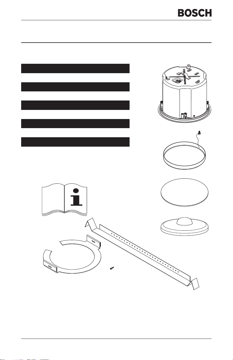
Packing List
Figure Quantity Part
A 1 Speaker System
B 1 Grille
C 1 Owner's Manual
D 1
E1
F 2
G1
H 2
Ceiling Cutout Template
Paint Shield
Tile Rails
C-Ring Support
Support Ring Screws
A
B
D
C
G
Figure 1: Bosch LC2-PC60G6-12 Packing List
Bosch Security Systems | 2008-05
H(
E
x2)
F(x2)
1
Page 4
Bosch LC2-PC60G6-12 Models
Model
LC2-PC60G6-12
Description
Prosound 60W12'' Ceiling Speaker
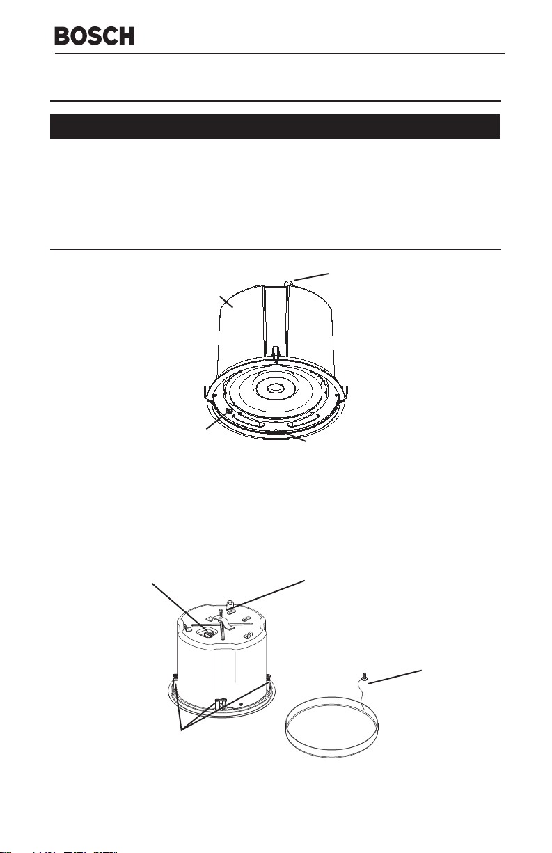
Product Feature Identification
Steel
Backcan
Tap
Selector
Figure 2: Bottom of Speaker
Mounting Tab
Pendant
Mount
Tabs (x3)
Screws (x4)
Ceramic Connector
Rotating Mounting
Tabs (x4)
3/8” Threaded
Rigging Point
Grille Safety
Tether
Grille
Figure 3: Top of Speaker
Page 5
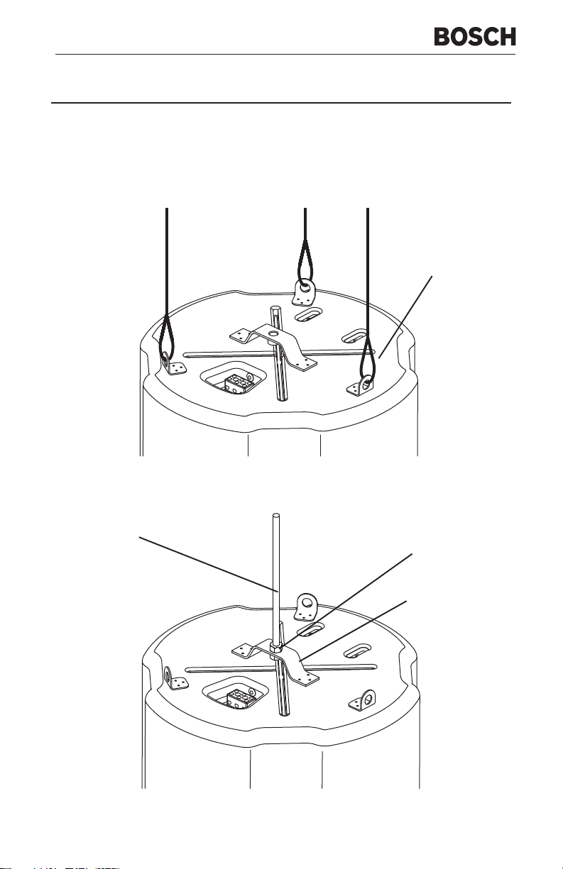
Open Ceiling Installation
The Bosch LC2-PC60G6-12 must be suspended from the back of the can in both open
ceiling and ceiling tile applications, using either the 3 pendant mount tabs or the 3/8”
threaded rigging point. To prevent rattles, rotate the 4 mounting tabs towards the can,
then tighten the mounting tab screws.
Pendant Mount
Tabs (x3)
Figure 4a: Pendant Mount Suspension
Threaded Rod
3/8” Nut
(Loctite Applied)
Rigging Plate with
Integrated Nut
(Loctite Applied)
Figure 4b: 3/8” Threaded Rod Suspension
Page 6

Ceiling Tile Installation
Step 1: Cut the Hole (Figure 5)
Cut out the hole by tracing the cardboard template or with a circular cutter set to the
appropriate cutout size. If the wire has been pre-installed, pull the wiring through the cutout
hole.
Figure 5: Cut Ceiling Hole
Step 2: Install C-Ring and Tile Rails (Figure 6)
For suspended ceiling installations, insert the C-ring through the hole cut in the ceiling tile.
Place the C-ring around the hole with the tabs located as shown in Figure 6. Insert the tile
rails through the cut hole in the ceiling tile. Snap the two rails into the two tabs in the C-ring
and align the rails so that the ends extend OVER the T-channel grid on the side of the tile.
Secure the rails onto the C-ring tabs by inserting a screw though each tab into the rail, as
shown in Figure 6.
Figure 6: Secure Rails to C-Ring
Bosch Security Systems | 2008-05
4
Page 7

Installation Note: Tile Rails and C-Ring
The tile rail accessory is designed to fit either standard 24-inch-wide or
600-mm-wide tiles. It is important to note that the tile rail pieces do not
actually attach to the T-grid struts.The ends of the rails sit OVER the T-
punched at regular intervals with holes along their length.This allows the C-ring to be
positioned at any point along the rail. If the tile comes out or falls apart, the ends of
the support rails fall onto the T-grid, which prevents the speaker assembly from
falling. Always use all included support hardware when installing into suspended
ceiling tiles to make sure the installation is secure. For sheetrock ceiling installations,
the tile rail is not needed, but the C-ring should be used to reinforce the ceiling
material and to spread out the pressure from the speaker hold-down tabs. Guide the
C-ring through the cut hole in the ceiling, and place it on the back side of the hole
before inserting the speaker.
grid strut. Normally, the tile supports the rails. The tile rails are pre-
Installation Note: Ceiling Tile Caution
When mounting the LC2-PC60G6-12 into 2'x2' or 2'x4' suspended ceiling
tiles or sheetrock ceilings, DO NOT install the LC2-PC60G6-12 without using
either the 3/8” threaded rod rigging point or the pendant mounts. Ceiling tiles
sag and distort, even with the tile bridge installed. If the cables are used, they MUST be
strung taut. The threaded rod or cables MUST support most of the weight of the
speaker to ensure that the LC2-PC60G6-12 does not deform the ceiling.
are not designed to support any substantial weight and will cause the tile to
Step 3: Attach Wiring to the Ceramic Connector (Figure 7)
Insert the bare end of wire into the appropriate connector terminals as described below
and screw down the hold-down screw until tight, using a small screwdriver.
Screwdriver
Figure 7: Tighten with Screwdriver
Bosch Security Systems | 2008-05
5
Page 8

Step 4: Mount the Speaker Into the Ceiling (Figure 8)
Push the speaker into the ceiling hole until the front baffle rim is flush with the ceiling.
Tighten the mounting tabs by turning the screw clockwise until the speaker is secure.
Please note that the first clockwise quarter turn rotates the attachment tabs outward.
The remaining turns tighten the tabs down onto the back of the ceiling surface (see
Figure 9).
Installation Note:
See Page 3 for possible installation methods. If 3/8” threaded rod is to be used in a
ceiling tile installation, the threaded rod must be installed to the threaded rigging point
before installing into the ceiling.
Installation Note: Mounting
Tabs
For each attachment screw, first turn
one half turn counterclockwise to
release the counting tab from its guide.
Figure 8: Mount Speaker into
Ceiling
Bosch Security Systems | 2008-05
Figure 9: Tighten Mounting Tabs
6
Page 9

Step 5: Adjust Tap Selector
(Figure 10)
The tap selector switch is located on the
front baffle. Adjust the speaker to the
appropriate tap setting before installing the
grille. In some 70V/100V constant voltage
installations it is advisable to leave the
grilles off if final speaker audio level
balance adjustments are to be made later.
After the levels are adjusted the grilles can
then be installed.
Step 6: Attach the Grille (Figure 11)
Installation Note: Grille Safety
Feature
Bosch grilles features a unique safety
tether to prevent the grille from falling if
the grille is removed or comes loose
after installation.
Figure 10: Adjust Tap Selector
First, install the grille’s safety tether by
pushing the grille fastener into the hole in
the front of the baffle (see Figure 11).
Second, press the grille into place until the
front of the grille is flush with the rim of the
baffle. Make sure the grille is securely
seated to prevent it from vibrating loose. If
you need to remove the grille, the easiest
way is to insert two bent paper clips or
other pointed objects into holes in the
grille, then apply slow even pressure to
pull down on the grille until that section of
the grille comes out slightly. Continue the
same procedure around the perimeter of
the grille, loosening a portion at a time
until the grille is removed.
Bosch Security Systems | 2008-05
Figure 11: Attach the Grille
7
Page 10

Appendix A - Painting the Speaker
If the speaker is installed in an area where the interior design requires a color match, the
Bosch LC2-PC60G6-12 is simple to paint. The speaker can accommodate almost any
type of latex or oil based paint. The bezel/rim can be painted before installation or after
mounting into the ceiling.
Painting Process
Clean the rim and grille with mineral spirits or
other light solvent. Do not use harsh solvents
such as gasoline, kerosene, acetone, or
other chemicals. If you use these cleaners
you may permanently damage the enclosure.
Also, don’t use abrasives products such as
sandpaper or steel wool. Either by rolling or
spraying, apply two or more thin coats of
paint. If you are spraying, hold the spray can
at the angles shown in Figure 13. If you are
painting the grille also, you must first remove
the internal grille cloth. Spray painting is
strongly recommended. If the grille is rolled
or brush painted, the grille may become
clogged with paint and the sound quality will
suffer. After the paint has dried, replace the
internal grille cloth. If you wish to paint the
speaker along with the ceiling after
installation, insert a plastic or cardboard paint
shield into the front of the speaker (see
Figure 12) to mask the drivers and internal
baffle, paint the speaker, then remove the
shield.
Paint
Shield
Speaker
Figure 12: Installing Paint Shield
Before Painting
45° 45°
Baffle
Figure 13: Spray-Painting Angles
Bosch Security Systems | 2008-05
180°
180°
Can
(do not
paint)
8
Page 11

Appendix B - Specifications
Figure 14: Dimension Drawings
snoisnemiD
:)retemaiDxhtpeD(
:retemaiDtuotuC")02.51(mm683
:thgieWs)bl3.92(gk3.31
:noitcurtsnoCtenibaC
:recudsnarT
:metsySgnitnuoM
:sroloCelbaliavAe
:noitcurtsnoCellirGe
:ngiseDcitsuocA
:esnopseRycneuqeFr
:)smho8(gnildnaHrewoPMSRW001
:)V07(gnildnaHrewoP4W6otpU
:)V001(gnildnaHrewoP4
:)m1/W1LPS(ytivitisneSdB001
:noitarugifnoCtupnI0V01/V07;mhO8
:spaTrewoPV074W6,W23,W61,W8,W4
:spaTrewoPV0014
:seirosseccAngiRgnitnuoM,egdirBeliT
Bosch Security Systems | 2008-05
mm414xmm333
)"13.61x"21.31(
detaR0-V49LUdnaerusolcnEleetSdetaocredwoP
lezeBdnaelffaB
)mm503(.ni21,B8-029
laixaoCycneiciffE-hgiH
revirD
tnioP-3detargetnI,srohcnAelggoTtnioP-4detargetnI
tnuoMyradnoceSlanotiddA,tnuoMtnadneP
anCraeRkcalBhtiw)ecafruSelbatniaP(elffaBtihW
rhteTytefaShtiwleetSdetaoCredwoP
,depmaDyllanretnI,ngiseDyaW-owT,tenibaCdetroP
CSAhtiwremrofsnarTW46,revossorCevissaP
Hzk02-zH57
W6otpU
W6,W23,W61,W8
9
Page 12

Notes
Bosch Security Systems | 2008-05
10
Page 13

Notes
Bosch Security Systems | 2008-05
11
Page 14

For more in formation visit
www.boschsecuritysystems.com
© Bosch Security Systems B.V.
Data subject to change w ithout notice
2008-05 | en
 Loading...