

Bosch LBB 3422/20, LBB 4511/00, LBB 4512/00, LBB 4540/04, LBB 4540/08 Operation Manual
...
Language Distribution System
Integrus
en Operation manual


Table of contents
1
Safety 6
2
About this manual 7
2.1 Purpose 7
2.2 Intended audience 7
2.3 Related documentation 7
2.4 Alerts and notice signs 7
2.5 Copyright and disclaimer 7
2.6 Document history 8
3
System Overview 9
3.1 System Overview 9
3.2 Integrus Transmitters 11
3.3 Audio input and Interpreter module 13
3.4 Integrus Radiators 14
3.5 Integrus Receivers 17
3.6 Receiver Headphones 18
3.7 Integrus Charging Units 19
4
Planning 20
4.1 System technology 20
4.1.1 IR radiation 20
4.1.2 Signal Processing 21
4.1.3 Quality modes 21
4.1.4 Carriers and channels 22
4.2 Aspects of Infrared distribution systems 23
4.2.1 Directional sensitivity of the receiver 23
4.2.2 The footprint of the radiator 23
4.2.3 Ambient lighting 25
4.2.4 Objects, surfaces and reflections 26
4.2.5 Position the radiators 26
4.2.6 Overlapping footprints and black spots 29
4.3 Plan an Integrus infrared radiation system 30
4.3.1 Rectangular footprints 30
4.3.2 Plan radiators 31
4.3.3 Cabling 32
5
Installation 33
5.1 Integrus Transmitters 33
5.2 Audio input and Interpreter module 33
5.3 Medium and High Power Radiators 35
5.3.1 Attach mounting plate to the suspension bracket 36
5.3.2 Attach the suspension bracket 37
5.3.3 Mount radiator on a floor stand 37
5.3.4 Mount radiator on a wall 38
5.3.5 Mount radiator on a ceiling 40
5.3.6 Mount radiator on horizontal surfaces 40
5.3.7 Secure the radiator with safety cord. 40
5.4 Integrus receivers 40
5.5 Integrus Charging Units 41
Language Distribution System Table of Contents | en 3
Bosch Security Systems B.V. Operation manual 2013.11 | V1.4 |

6
Connection 42
6.1 Integrus Transmitters 42
6.2 Connect the DCN Next Generation system 42
6.3 Connect other external audio sources 43
6.4 Connect an emergency signal 44
6.5 Connect to another transmitter 45
6.6 Connect radiators 46
7
Configuration 48
7.1 Integrus transmitter 48
7.1.1 Overview 48
7.1.2 Navigate through the menu 49
7.1.3 Example 50
7.2 Setup the transmitter 51
7.2.1 Main menu 51
7.2.2 Set transmission (4A) 52
7.2.3 Set network mode (4B) 52
7.2.4 Set number of channels (4C) 53
7.2.5 Set channel quality and assign inputs to channels (4D) 54
7.2.6 Language list (4E) 55
7.2.7 Set channel names (4F) 55
7.2.8 Disable or enable carriers (4G) 56
7.2.9 View carrier assignments (4H) 56
7.2.10 Configure auxiliary inputs (4I) 57
7.2.11 Set sensitivity of the inputs (4J, 4K, 4L) 57
7.2.12 Enable / disable IR-monitoring (4M) 58
7.2.13 Enable / disable headphone output (4N) 58
7.2.14 Choose transmitter name (4O) 58
7.2.15 Reset all options to factory default values (4P) 59
7.3 Integrus Radiators 59
7.3.1 Set the output power selection switch 59
7.3.2 Set the delay switches 60
7.4 Determine the radiator delay switch positions 60
7.4.1 System with one transmitter 60
7.4.2 System with two or more transmitters in one room 63
7.4.3 Systems with more than 4 carriers and a radiator under a balcony 65
8
Testing 66
8.1 Integrus Transmitter 66
8.2 Integrus Receiver 67
8.3 Test the coverage area 67
9
Operation 69
9.1 Integrus transmitter 69
9.1.1 Start-up 69
9.1.2 View transmitter status 69
9.2 Integrus Radiators 69
9.3 Integrus Receivers 70
9.3.1 Normal operation 70
9.3.2 Storage of receiver 71
9.4 Integrus Charging Units 71
4 en | Table of Contents Language Distribution System
2013.11 | V1.4 | Operation manual Bosch Security Systems B.V.

10
Troubleshooting 72
10.1 Fault messages 72
10.2 Faultfinding guide 73
10.3 Service requests 75
11
Maintenance 76
12
Technical Data 77
12.1 Electrical Data 77
12.1.1 Overall system characteristics 77
12.1.2 Transmitters and Modules 77
12.1.3 Radiators and Accessories 78
12.1.4 Receivers, Battery Packs and Charging Units 78
12.1.5 Cables and connectors 80
12.2 Mechanical Data 81
12.2.1 Transmitters and Modules 81
12.2.2 Radiators and Accessories 81
12.2.3 Receivers, Battery Packs and Charging Units 82
12.3 Ambient Conditions 83
12.3.1 Overall system conditions 83
12.4 Rules and Standards 84
12.4.1 Overall system conformance 84
12.5 Guaranteed rectangular footprints 85
12.5.1 Metric values of radiators with hardware version higher than 2.00 85
12.5.2 Imperial values of radiators with hardware version higher than 2.00 87
12.5.3 Metric values of radiators with hardware version lower than 2.00. 89
12.5.4 Imperial values of radiators with hardware version lower than 2.00. 91
Language Distribution System Table of Contents | en 5
Bosch Security Systems B.V. Operation manual 2013.11 | V1.4 |

Safety
Prior to installing or operating the products, always read the installation instructions in
section Installation, page 33 and the Safety Instructions which are provided with the mains
powered products.
!
Warning!
To prevent possible hearing damage, do not listen at high volume levels for long periods.
1
6 en | Safety Language Distribution System
2013.11 | V1.4 | Operation manual Bosch Security Systems B.V.
About this manual
Purpose
The purpose of this document is to provide information required for installing, configuring,
operating, maintaining and troubleshooting an Integrus Language Distribution System.
Intended audience
This document is intended for installers and users of an Integrus Language Distribution
System.
Related documentation
– DCN Next Generation operation manual. Refer to the product related information at:
www.boschsecurity.com
Alerts and notice signs
Four types of signs can be used in this manual. The type is closely related to the effect that
may be caused if it is not observed. These signs - from least severe effect to most severe
effect - are:
Notice!
Containing additional information. Usually, not observing a ‘notice’ does not result in damage
to the equipment or personal injuries.
!
Caution!
The equipment or the property can be damaged, or persons can be lightly injured if the alert
is not observed.
!
Warning!
The equipment or the property can be seriously damaged, or persons can be severely injured
if the alert is not observed.
Danger!
Not observing the alert can lead to severe injuries or death.
Copyright and disclaimer
All rights reserved. No part of this document may be reproduced or transmitted in any form by
any means, electronic, mechanical, photocopying, recording, or otherwise, without the prior
written permission of the publisher. For information on getting permission for reprints and
excerpts, contact Bosch Security Systems B.V..
The content and illustrations are subject to change without prior notice.
2
2.1
2.2
2.3
2.4
2.5
Language Distribution System About this manual | en 7
Bosch Security Systems B.V. Operation manual 2013.11 | V1.4 |

Document history
Release date Documentation version Reason
2013.10.24 V1.3 New document layout.
2013.11.29 V1.4 EOL product information
removed.
2.6
8 en | About this manual Language Distribution System
2013.11 | V1.4 | Operation manual Bosch Security Systems B.V.
System Overview
System Overview
Integrus is a system for wireless distribution of audio signals via infrared radiation. It can be
used in a simultaneous interpretation system for international conferences where multiple
languages are used. To enable all participants to understand the discussion, interpreters
simultaneously translate the speaker's language as required. These interpretations are
distributed throughout the conference venue, and delegates select the language of their
choice and listen to it through headphones. The Integrus system can also be used for music
distribution (mono as well as stereo).
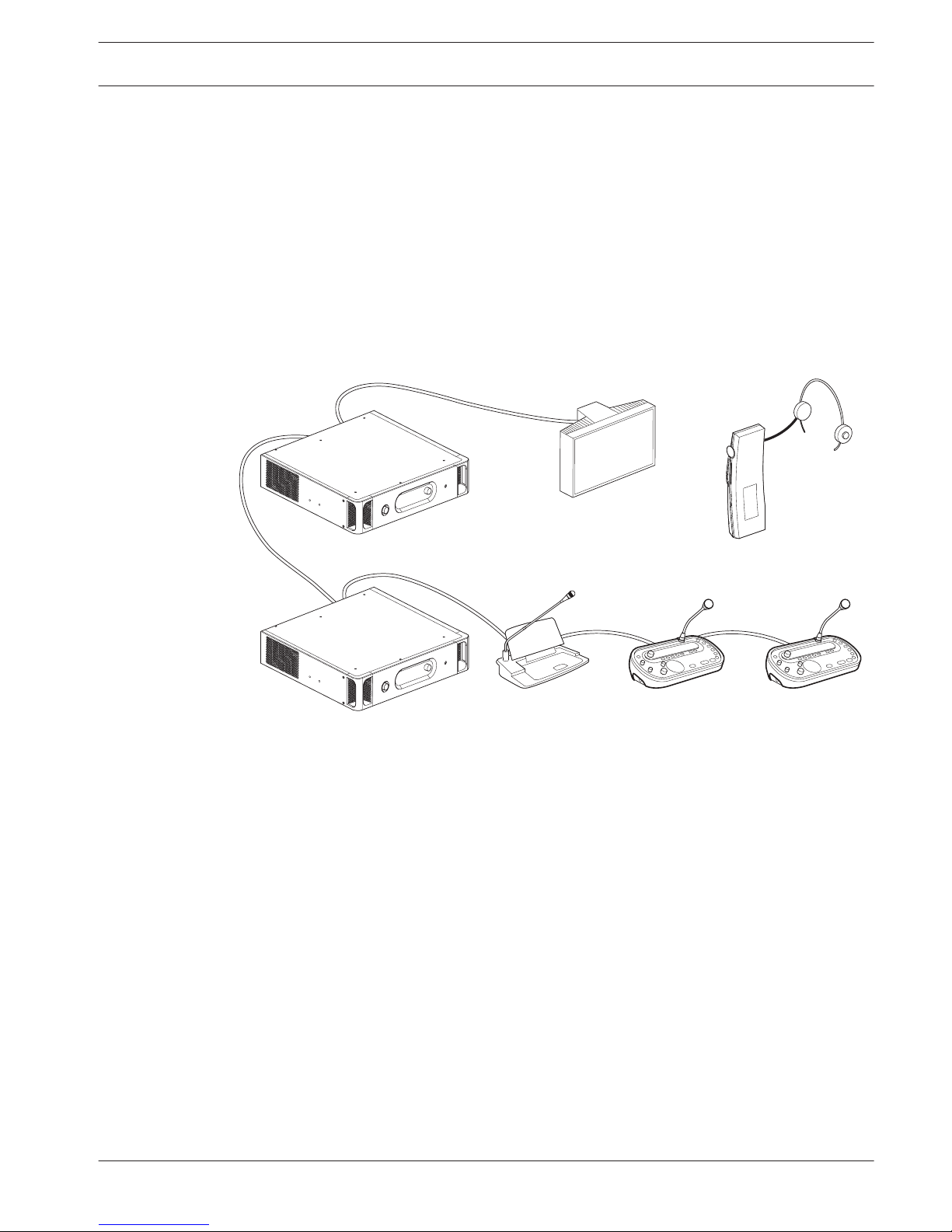
Figure 3.1: Integrus system overview (with DCN-system as input)
The Integrus Language Distribution System comprises one or more of the following:
Infrared transmitter
The transmitter is the core of the Integrus system. Four types are available:
– INT‑TX04 with inputs for 4 audio channels
– INT‑TX08 with inputs for 8 audio channels
– INT‑TX16 with inputs for 16 audio channels
– INT‑TX32 with inputs for 32 audio channels
The transmitter can be directly connected to the DCN Next Generation conference system
(see section Connection, page 42).
3
3.1
Language Distribution System System Overview | en 9
Bosch Security Systems B.V. Operation manual 2013.11 | V1.4 |

Audio input and Interpreter module
The audio input and interpreter’s module can be mounted in the transmitter housing to
connect the transmitter to a wide range of conference systems:
– LBB 3422/20 Integrus audio input and interpreters module to connect to analogue
discussion and conference systems (such as CCS 900) or to LBB 3222/04 6-channel
interpreters desks.
Infrared radiators
Two radiators are available:
– LBB 4511/00 medium-power radiator for small/ medium conference venues
– LBB 4512/00 high-power radiator for medium/large conference venues
The radiators can be mounted on walls, ceilings or floor stands.
Infrared receivers
Three multi-channel infrared receivers are available:
– LBB 4540/04 for 4 audio channels
– LBB 4540/08 for 8 audio channels
– LBB 4540/32 for 32 audio channels
The receivers can operate with a rechargeable NiMH battery pack or with disposable batteries.
Charging circuitry is incorporated in the receiver.
Charging equipment
Equipment is available for charging and storing 56 infrared receivers. Two versions are
available:
– LBB 4560/00 charging suitcase for portable systems
– LBB 4560/50 charging cabinet for permanent systems
10
en | System Overview Language Distribution System
2013.11 | V1.4 | Operation manual Bosch Security Systems B.V.
Integrus Transmitters
The transmitter is the central element of the Integrus system. It accepts asymmetrical audio
sources from a maximum of 32 external channels (dependent on the transmitter type) and can
be used with the DCN Next Generation conference system. It can also be used with analogue
discussion and interpretation systems (e.g. CCS 900 with up to 12 interpreter desks), or as a
stand-alone system distributing external audio sources.
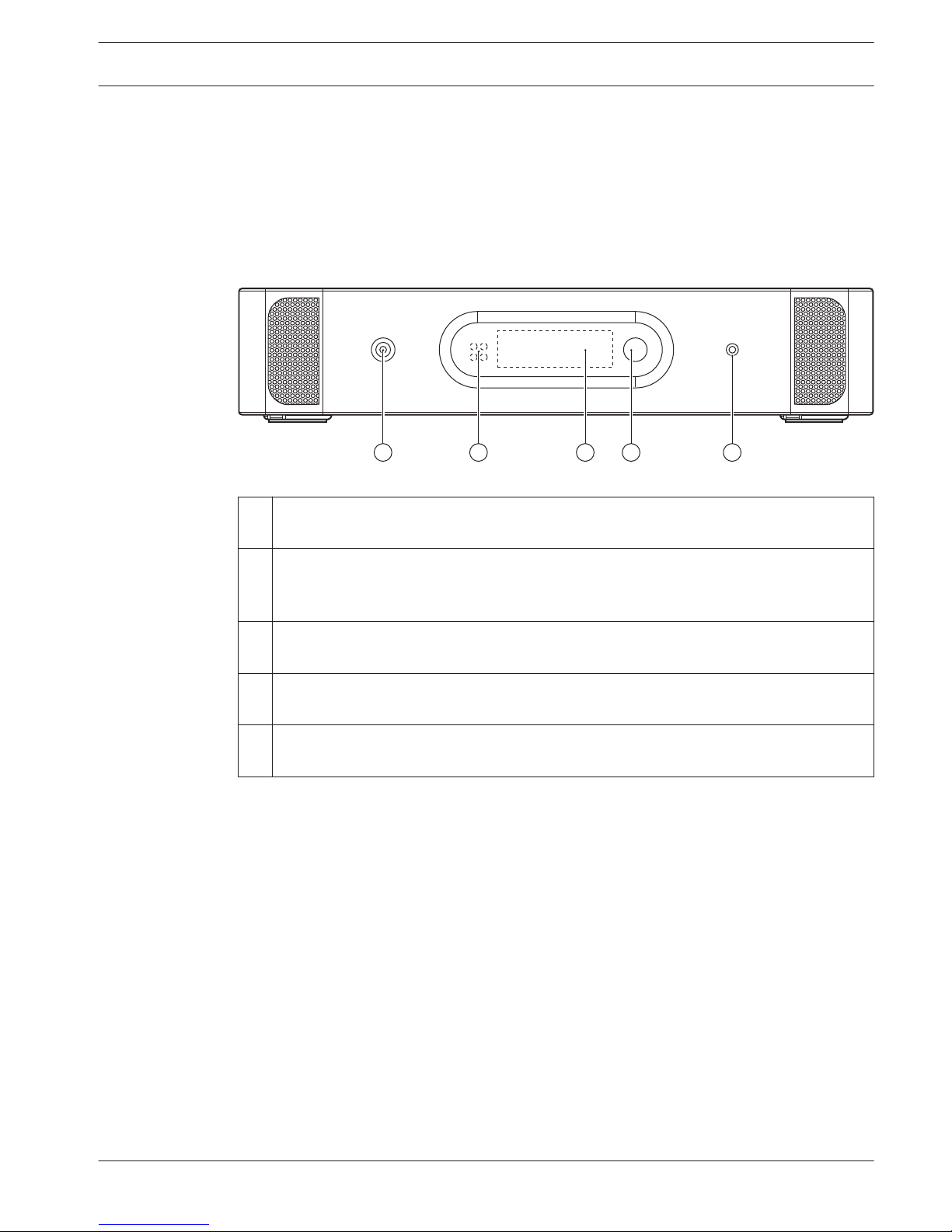
Transmitter front view
32 4 51
Figure 3.2: Transmitter, front view
1
Mains on/off switch - After switching the mains on, the transmitter starts up and the
display (3) will light-up.
2 Mini IR-radiator - Four IREDs, transmitting the same infrared signal as the radiator
output. This can be used for monitoring purposes. They can be disabled via the
configuration menu.
3 Menu display - A 2x16 character LCD-display gives information about the transmitter
status. It is also used as a an interactive display for configuring the system.
4 Menu button - A turn-and-push button to operate the configuration software in
combination with the display (3)
5 Monitoring headphone output - A 3.5 mm (0.14 inch) jack socket to connect a
headphone for monitoring purposes. It can be disabled via the configuration menu
3.2
Language Distribution System System Overview | en 11
Bosch Security Systems B.V. Operation manual 2013.11 | V1.4 |
Transmitter rear view
1 3 5 7 9 11 13 15 17 19 21 23 25 27 29 31
0 2 4
4 5 6
2 31
8 10 12 14 16 18 20 22 24 26 28 30
Network
1 2
1 2
6
97
53
8
4
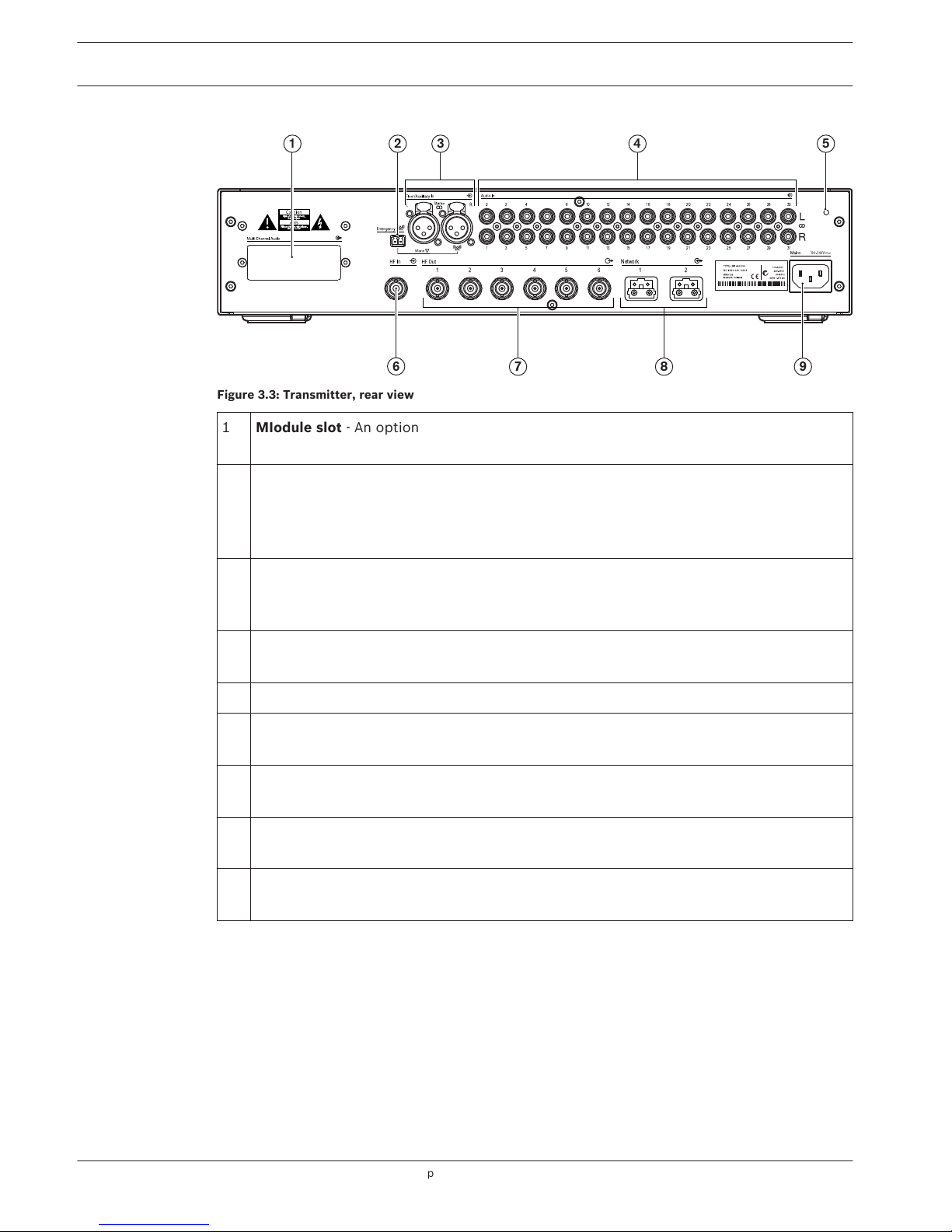
Figure 3.3: Transmitter, rear view
1
MIodule slot - An optional audio interface module can be mounted in the transmitter
housing. Its connectors are accessible via an opening at the back of the transmitter.
2 Emergency switch connector - A terminal block socket for a single, 'normally open'
switch. When the switch is closed, the audio signal on the Aux-right input is distributed
on all output channels, overriding all other audio inputs. A matching cable connector is
provided.
3 Auxiliary audio inputs - Two female XLR connectors for extra audio inputs. They can be
used to connect auxiliary symmetrical audio signals such as a music installation, the
original floor language or emergency messages.
4 Audio signal inputs - 4, 8, 16 or 32 cinch plugs to connect external asymmetrical audio
input signals. The number of connectors depends on the transmitter type.
5 Earth connection point - Only used for factory testing purposes.
6 Radiator signal loop-through input - A HF BNC connector to loop-through the radiator
output of another transmitter.
7 Radiator signal outputs - Six HF BNC connectors, used to connect the radiators. Up to
30 radiators can be loop-through connected to each output.
8 Optical network connections - Two connections used to connect directly to the DCN
Next Generation conference system with an optical network cable.
9 Mains input - Euro mains socket. The transmitter has automatic mains voltage selection.
A mains cable is provided
The following sections give more information about the mentioned subject:
– Installation: Integrus Transmitters, page 33
– Connection: Connection, page 42
– Configuration: Integrus transmitter, page 48 and Setup the transmitter, page 51
– Operation: Integrus transmitter, page 69
12
en | System Overview Language Distribution System
2013.11 | V1.4 | Operation manual Bosch Security Systems B.V.

Audio input and Interpreter module
The audio input and interpreter’s module can be mounted in the transmitter housing to
connect the transmitter to a wide range of conference systems:
– LBB 3422/20 Integrus audio input and interpreters module to connect to analogue
discussion and conference systems (such as CCS 900) or to LBB 3222/04 6-channel
interpreters desks. See the DCN NG operation manual for information of this product (on
the DCN NG DVD or the product/DCN system related information section at:
www.boschsecurity.com.
– This module must be mounted inside the transmitter housing (see section Audio
input and Interpreter module, page 33).
3.3
Language Distribution System System Overview | en 13
Bosch Security Systems B.V. Operation manual 2013.11 | V1.4 |
Integrus Radiators
The radiators accept the carrier signals generated by the transmitter and emit infrared
radiation carrying up to 32 audio distribution channels. They are connected to one or more of
the six HF BNC outputs of the IR transmitter. A maximum of 30 radiators can be connected to
each of these outputs by means of loop-through connections.
The LBB 4511/00 has an infrared output of 21 Wpp, while the LBB 4512/00 has an infrared
output of 42 Wpp. Both have an automatic mains power voltage selection and are switched on
automatically when the transmitter is switched on.
The attenuation of the signal by the cable is equalized automatically by the radiator. When the
radiator is supplied with power and the transmitter is switched on, the radiator initializes the
equalization. The red LED flash for a brief period of time to indicate that the initialization is in
progress.
When not receiving carrier waves, the radiators switch to standby mode. There is also a
temperature protection mode which automatically switches the radiators from full to half
power or from half power to standby if the temperature of the IREDs becomes too high.
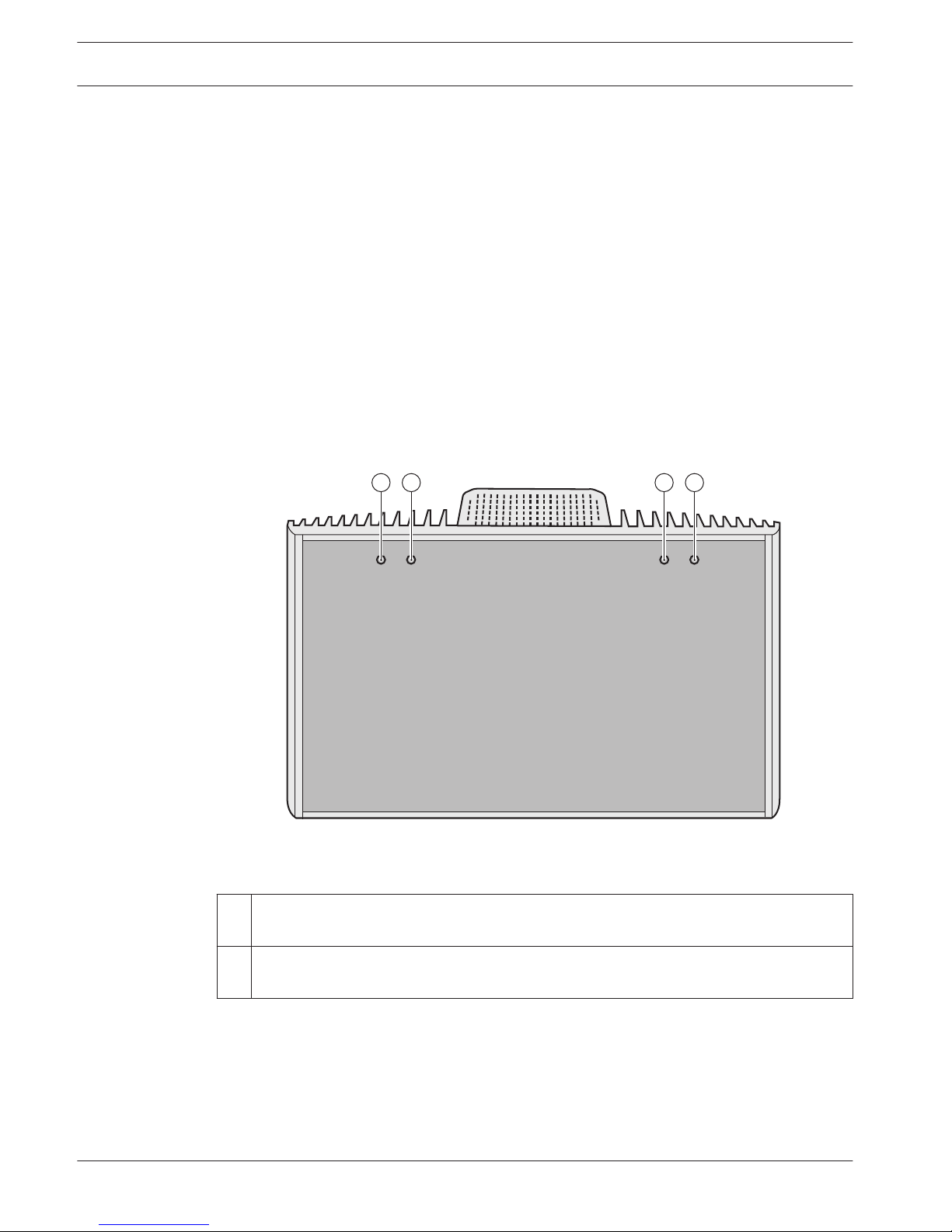
1 21 2
Figure 3.4: LBB 4512/00 High Power Radiator (Front view)
1
Red indicator LEDs - Give an indication of the radiator status, see section Integrus
Radiators, page 69.
2 Amber indicator LEDs - Give an indication of the radiator status, see section Integrus
Radiators, page 69.
3.4
14 en | System Overview Language Distribution System
2013.11 | V1.4 | Operation manual Bosch Security Systems B.V.
3
2
1
4
5
6
7
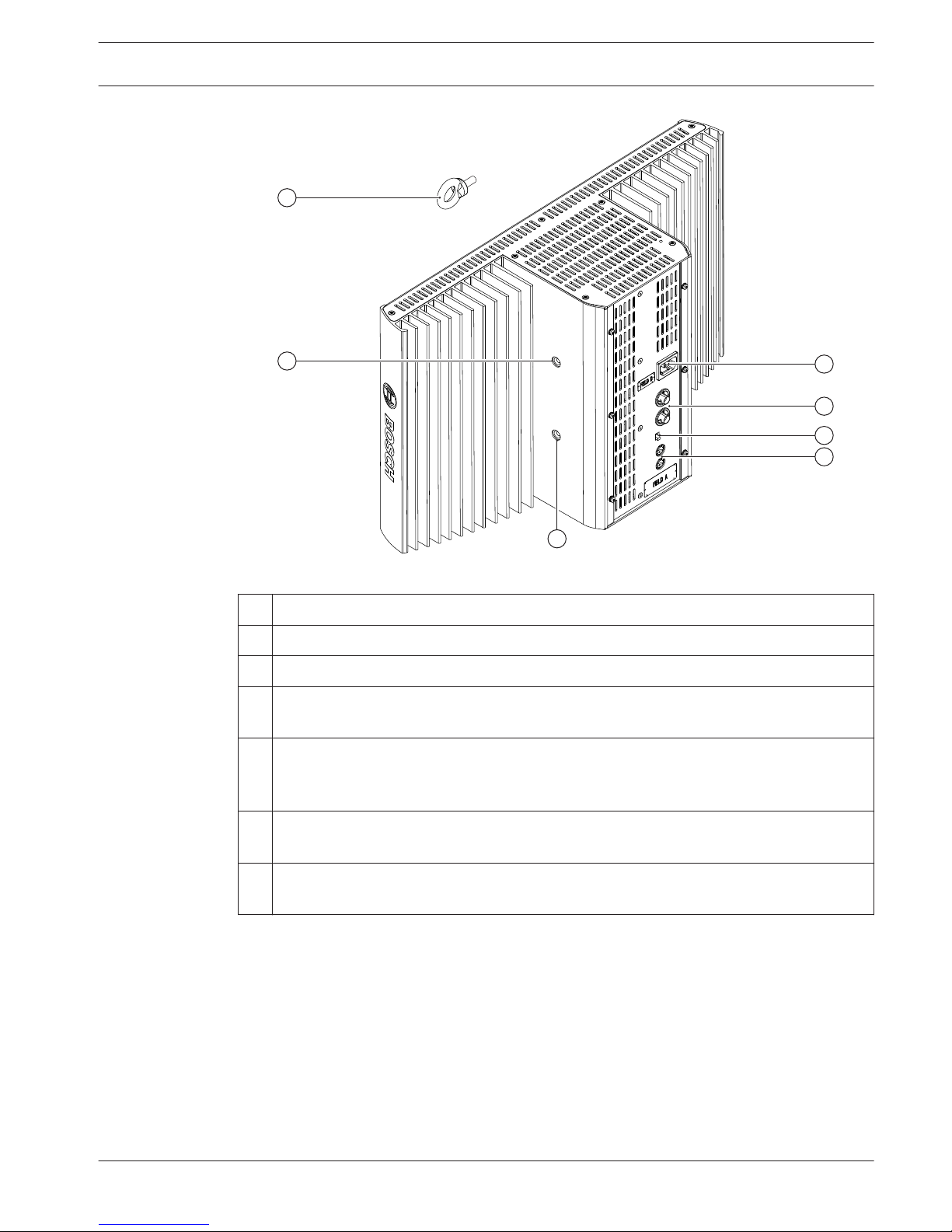
Figure 3.5: LBB 4512/00 Radiator (Side and rear view)
1
Safety eye - To mount a safety cord for extra security.
2 Safety eye hole - Tapped hole to mount the safety eye.
3 Bracket hole - Tapped hole to mount the suspension bracket.
4 Mains input - Male Euro mains connector. The radiators have automatic mains voltage
selection.
5 IR signal input/loop-through - Two HF BNC connectors for connecting the radiator to
the transmitter and for loop-through connection to other radiators. Automatic cable
termination is achieved by a built-in switch in the BNC connectors.
6 Output power selection switch - The radiators can be switched between full- and half-
power operation.
7 Delay compensation switches - Two 10-position switches to compensate for
differences in cable lengths to the radiators.
Language Distribution System System Overview | en 15
Bosch Security Systems B.V. Operation manual 2013.11 | V1.4 |
4 2
4
3
3
5
5
1
6
7
6
7
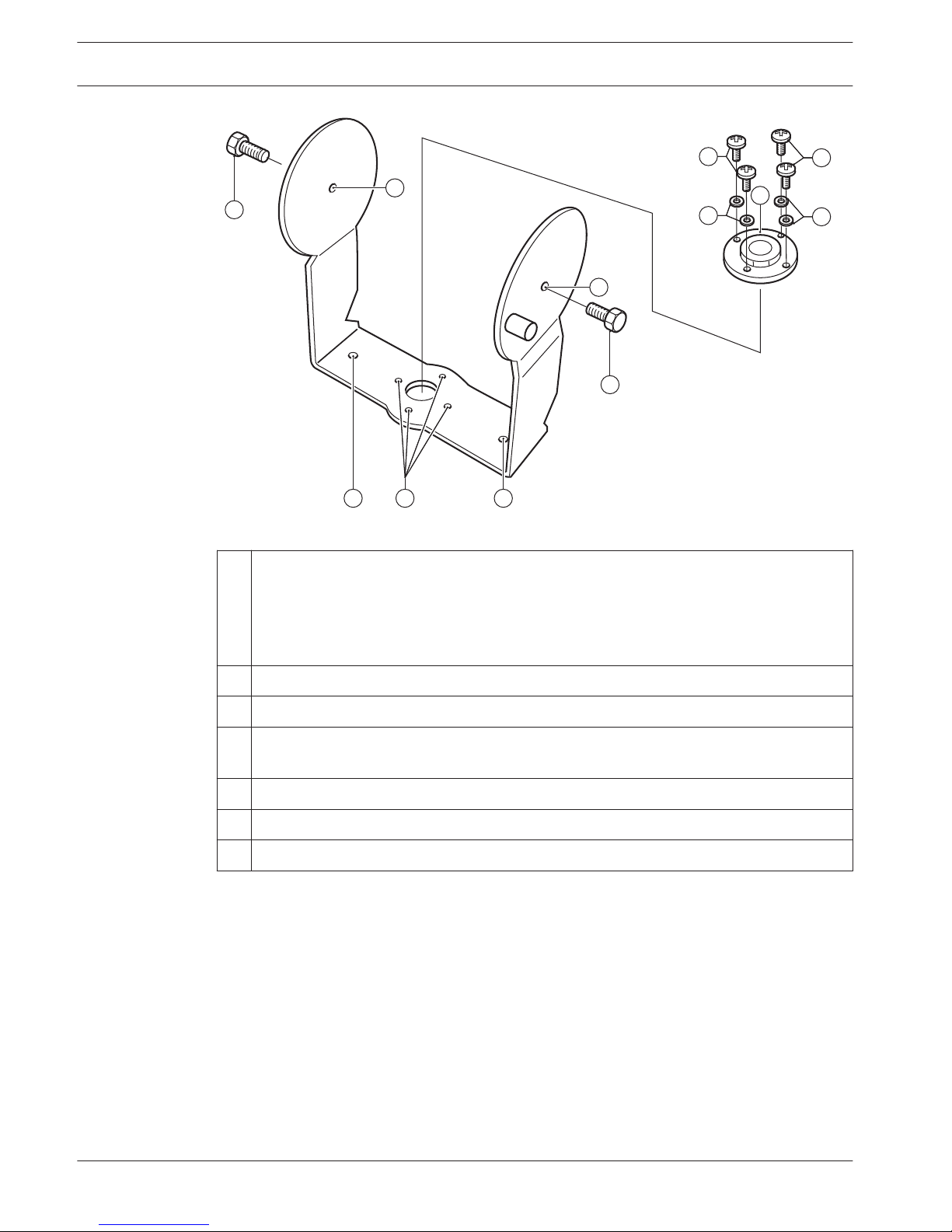
Figure 3.6: Suspension bracket and mounting plate of LBB 4511/00 and LBB 4512/00 Radiators
1
Mounting plate - Accessory plate to be used in case of mounting on a floor stand or
wall mounting.
Depending on the way of mounting, the mounting plate can be mounted at either one or
the other side of the bracket (see section Attach mounting plate to the suspension
bracket, page 36).
2 Mounting plate hole - Tapped holes to mount the mounting plate.
3 Radiator hole - Holes for bolts.
4 Mounting hole - Holes for screws to mount the bracket to the ceiling or on horizontal
surfaces.
5 Bolt - Bolt to mount the suspension bracket to the radiator.
6 Screw - Screw to mount the mounting plate to the suspension bracket.
7 Washer
The following sections give more information about the mentioned subject:
– Installation: Medium and High Power Radiators, page 35
– Configuration: Integrus Radiators, page 59
– Operation: Integrus Radiators, page 69
16
en | System Overview Language Distribution System
2013.11 | V1.4 | Operation manual Bosch Security Systems B.V.
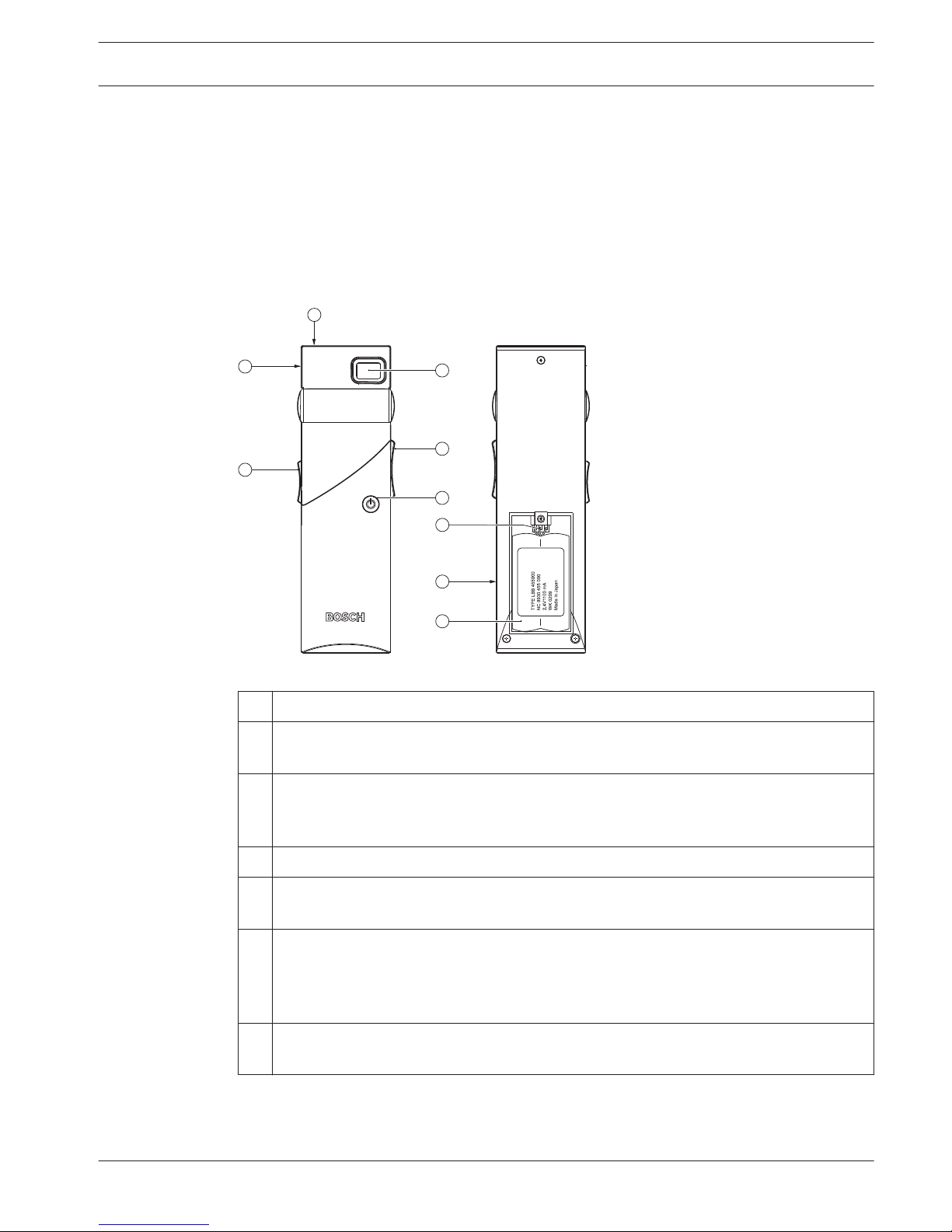
Integrus Receivers
LBB 4540 receivers are available for 4, 8 or 32 channels. They can operate with a rechargeable
NiMH battery pack or with disposable batteries and have controls for channel selection,
volume adjustment and an on/off push button. All receivers have a 3.5 mm (0.14 inch) stereo
jack output socket for mono or stereo headphones.
An LCD display shows the channel number and indicators for signal reception and low battery
power.
Charging circuitry is included in the receiver.
2
1
4
3
5
8
7
9
6
Figure 3.7: Receiver, front view and back view with open battery compartment
1
Charging indicator LED - Used in combination with the charging equipment.
2 Headphone connector - A 3.5 mm (0.14 inch) stereo jack output socket for the
headphone, with integrated Stand-by/Off-switch.
3 LCD Display - A two digit display showing the selected channel. An antenna symbol is
visible when the receiver picks up an infra red signal of adequate quality. A battery
symbol is visible when the battery pack or the batteries are almost empty.
4 Volume control - A slider to adjust the volume.
5 Channel selector - An up/down switch to select an audio channel. The channel number
is shown on the LCD display.
6 On/Off button - When a headphone is connected, the receiver switches to Stand-by
state. Pressing the On/Off button switches the receiver from Stand-by to On. To switch
back to Stand-by, press and hold the button for approx. 2 seconds. When the
headphone is removed, the receiver switches automatically to the Off-state.
7 Battery pack connector - This connection is used to connect the battery pack to the
receiver. Charging is automatically disabled when this connector is not used.
3.5
Language Distribution System System Overview | en 17
Bosch Security Systems B.V. Operation manual 2013.11 | V1.4 |

8 Charging contacts - Used in combination with the charging equipment to recharge the
battery pack (if used)
9 Battery pack or disposable batteries - Either a rechargeable NiMH battery pack
(LBB 4550/10) or two disposable A‑-size 1.5 V batteries.
The following sections give more information about the mentioned subject:
– Installation: Integrus receivers, page 40
– Operation: Integrus Receivers, page 70
Receiver Headphones
The headphones connect with the receivers via a 3.5 mm (0.14 inch) stereo jack connector.
Suitable headphone types are:
– LBB 3441/10 Under the chin stereo headphones
– LBB 3442/00 Single earphone (mono)
– LBB 3443/00 Stereo headphones
– HDP‑ILN Induction Loop Neckband
– HDP‑LWN Lightweight Neckband headphone
– Or any other compatible type (see Technical Data, page 77)
3.6
18 en | System Overview Language Distribution System
2013.11 | V1.4 | Operation manual Bosch Security Systems B.V.
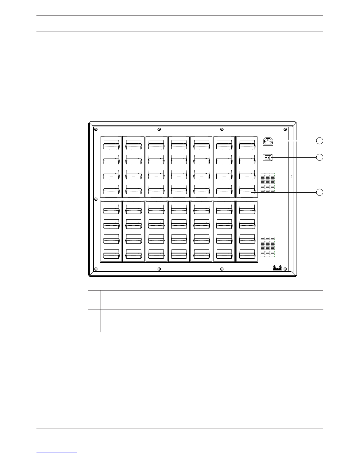
Integrus Charging Units
The charging units can recharge up to 56 receivers at once. The charging unit contains the
power supply with automatic mains voltage selection. The charging electronics and a charging
indicator LED are integrated in each receiver. The charging circuitry checks if a battery pack is
present and controls the charging process.
Two versions are available, which are functionally identical:
– LBB 4560/00 Charging suitcase for portable systems.
– LBB 4560/50 Charging cabinet for permanent systems. Suitable for either table-top or
wall-mounted use.
1
2
3
Figure 3.8: LBB 4560 Charging unit
1
Mains input - Male Euro mains socket. The charging unit has automatic mains voltage
selection. A mains cable is provided.
2 Mains on/off switch
3 Receiver positions - One charging unit can charge up to 56 receivers simultaneously.
The following sections give more information about the mentioned subject:
– Installation: Integrus Charging Units, page 41
– Operation: Integrus Charging Units, page 71
3.7
Language Distribution System System Overview | en 19
Bosch Security Systems B.V. Operation manual 2013.11 | V1.4 |
Planning
System technology
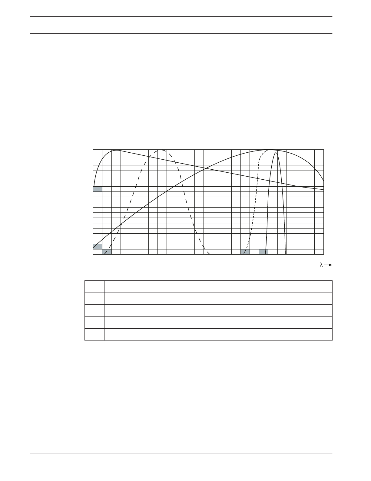
IR radiation
The Integrus system is based on transmission by modulated infrared radiation. Infrared
radiation forms part of the electromagnetic spectrum, which is composed of visible light, radio
waves and other types of radiation. It has a wavelength just above that of visible light. Like
visible light, it is reflected from hard surfaces, yet passes through translucent materials such
as glass. The infrared radiation spectrum in relation to other relevant spectra is shown in the
next figure.
100
75
1
4
2
50
25
0
400 500 600 700 800
5 3
900 1000 nm
%
Figure 4.1: Infrared radiation spectrum in relation to other spectra
1
Daylight spectrum
2 Sensitivity of the human eye
3 IR radiator
4 Sensitivity of IR sensor
5 Sensitivity of IR sensor with daylight filter
4
4.1
4.1.1
20 en | Planning Language Distribution System
2013.11 | V1.4 | Operation manual Bosch Security Systems B.V.
Signal Processing
The Integrus system uses high frequency carrier signals (typically 2-8 MHz) to prevent
interference problems with modern light sources (see section The footprint of the radiator,
page 23). The digital audio processing guarantees a constant high audio quality.
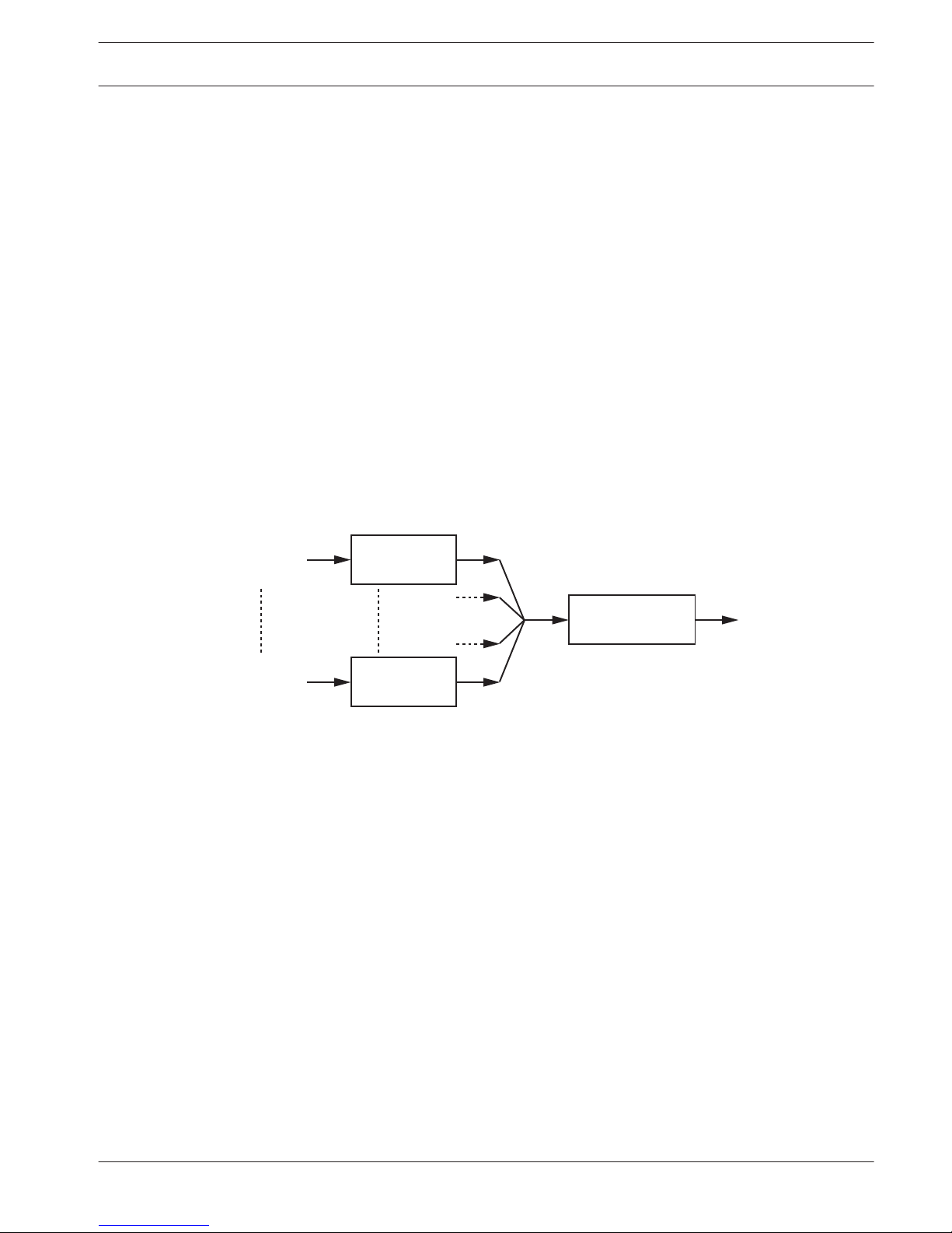
The signal processing in the transmitter consists of the following main steps (see the next
figure):
1. A/D conversion - Each analogue audio channel is converted to a digital signal.
2. Compression - The digital signals are compressed to increase the amount of information
that can be distributed on each carrier. The compression factor is also related to the
required audio quality.
3. Protocol Creation - Groups of up to four digital signals are combined into a digital
information stream. Extra fault algorithm information is added. This information is used
by the receivers for fault detection and correction.
4. Modulation - A high frequency carrier signal is phase-modulated with the digital
information stream.
5. Radiation - Up to 8 modulated carrier signals are combined and sent to the IR radiators,
which convert the carrier signals to modulated infrared light.
In the IR receivers a reverse processing is used to convert the modulated infrared light to
separate analogue audio channels.
A/D Conversion
& Compression
A/D Conversion
& Compression
Audio
Channel
Audio
Channel
Protocol Creation
& Modulation
4x
Carrier (to IR Radiators)
4x
Figure 4.2: Overview of the signal processing (for one carrier)
Quality modes
The Integrus system can transmit audio in four different quality modes:
– Mono, standard quality, maximum 32 channels
– Mono, premium quality, maximum 16 channels
– Stereo, standard quality, maximum 16 channels
– Stereo, premium quality, maximum 8 channels
The standard quality mode uses less bandwidth and can be used for transmitting speech. For
music the premium quality mode gives near CD quality.
4.1.2
4.1.3
Language Distribution System Planning | en 21
Bosch Security Systems B.V. Operation manual 2013.11 | V1.4 |

Carriers and channels
The Integrus system can transmit up to 8 different carrier signals (depending on the
transmitter type). Each carrier can contain up to 4 different audio channels. The maximum
number of channels per carrier is dependent on the selected quality modes. Stereo signals use
twice as much bandwidth as a mono signals; premium quality uses twice as much bandwidth
as standard quality.
Per carrier a mix of channels with different quality modes is possible, as long as the total
available bandwidth is not exceeded. The table below lists all possible channel combinations
per carrier:
Channel quality
Mono
Standard
Mono
Premium
Stereo
Standard
Stereo
Premium
Bandwidth
Possible
number
of
channels
per
carrier
4 4 x 10 kHz
2 1 2 x 10 kHz and 1 x 20 kHz
2 1 2 x 10 kHz and 1 x 10 kHz (left)
and
1 x 10 kHz (right)
1 1 1 x 20 kHz and 1 x 10 kHz (left)
and
1 x 10 kHz (right)
2 2 x 10 kHz (left) and 2 x 10 kHz
(right)
2 2 x 20 kHz
1 1 x 20 kHz (left) and 1 x 20 kHz
(right)
4.1.4
22 en | Planning Language Distribution System
2013.11 | V1.4 | Operation manual Bosch Security Systems B.V.
Aspects of Infrared distribution systems
A good infrared distribution system ensures that all delegates in a conference venue receive
the distributed signals without disturbance. This is achieved by using enough radiators, placed
at well planned positions, so that the conference venue is covered with uniform IR-radiation of
adequate strength. There are several aspects that influence the uniformity and quality of the
infrared signal, which must be considered when planning an infrared radiation distribution
system. These are discussed in the next sections.
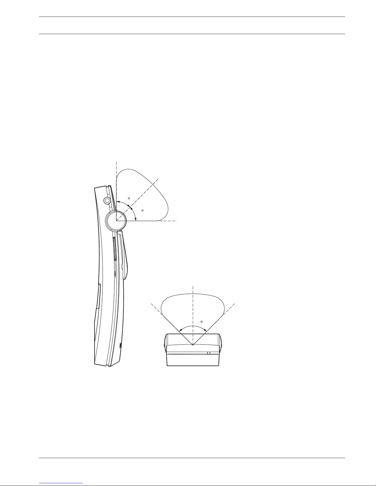
Directional sensitivity of the receiver
The sensitivity of a receiver is at its best when it is aimed directly towards a radiator. The axis
of maximum sensitivity is tilted upwards at an angle of 45 degrees (see the next figure).
Rotating the receiver will decrease the sensitivity. For rotations of less than +/- 45 degrees
this effect is not large, but for larger rotations the sensitivity will decrease rapidly.
45
45
90
Figure 4.3: Directional characteristics of the receivers
The footprint of the radiator
The coverage area of a radiator depends on the number of transmitted carriers and the output
power of the radiator. The coverage area of the LBB 4512/00 radiator is twice as large as the
coverage area of the LBB 4511/00. The coverage area can also be doubled by mounting two
radiators side by side. The total radiation energy of a radiator is distributed over the
transmitted carriers. When more carriers are used, the coverage area gets proportionally
smaller. The receiver requires a strength of the IR signal of 4 mW/m2 per carrier to work
4.2
4.2.1
4.2.2
Language Distribution System Planning | en 23
Bosch Security Systems B.V. Operation manual 2013.11 | V1.4 |
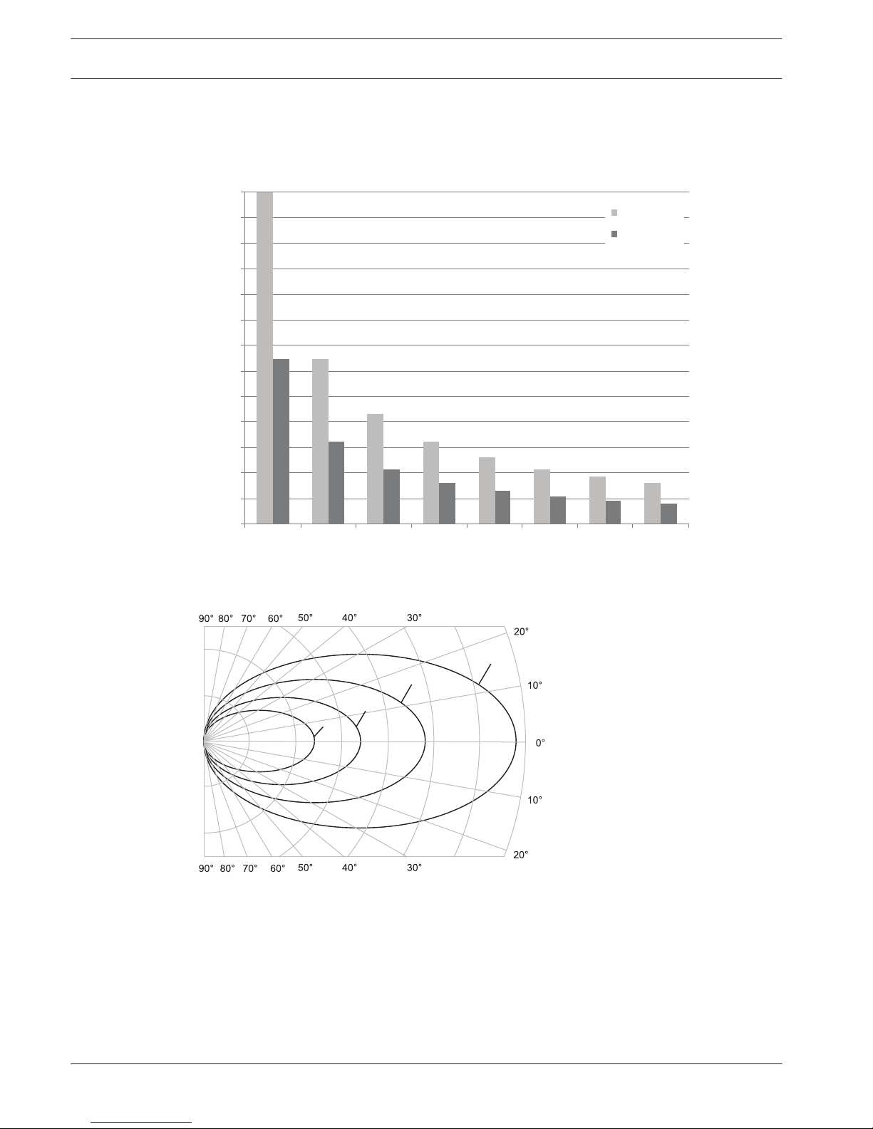
without errors (resulting in a 80 dB S/N ratio for the audio channels). The effect of the number
of carriers on the coverage area can be seen in the next two figures. The radiation pattern is
the area within which the radiation intensity is at least the minimum required signal strength.
0
200
400
600
800
1000
1200
1400
1600
1800
2000
2200
2400
2600
1 2 3 4 5 6 7 8
m
2
LBB4512/0 0
LBB4511/0 0
Figure 4.4: Total coverage area of LBB 4511/00 and LBB 4512/00 for 1 to 8 carriers
1
8
2
4
Figure 4.5: Polar diagram of the radiation pattern for 1, 2, 4 and 8 carriers
Footprint
The cross section of the 3-dimensional radiation pattern with the floor of the conference
venue is known as the footprint (the white area in the following three figures). This is the floor
area in which the direct signal is strong enough to ensure proper reception, when the receiver
is directed towards the radiator. As shown, the size and position of the footprint depends on
the mounting height and angle of the radiator.
24
en | Planning Language Distribution System
2013.11 | V1.4 | Operation manual Bosch Security Systems B.V.
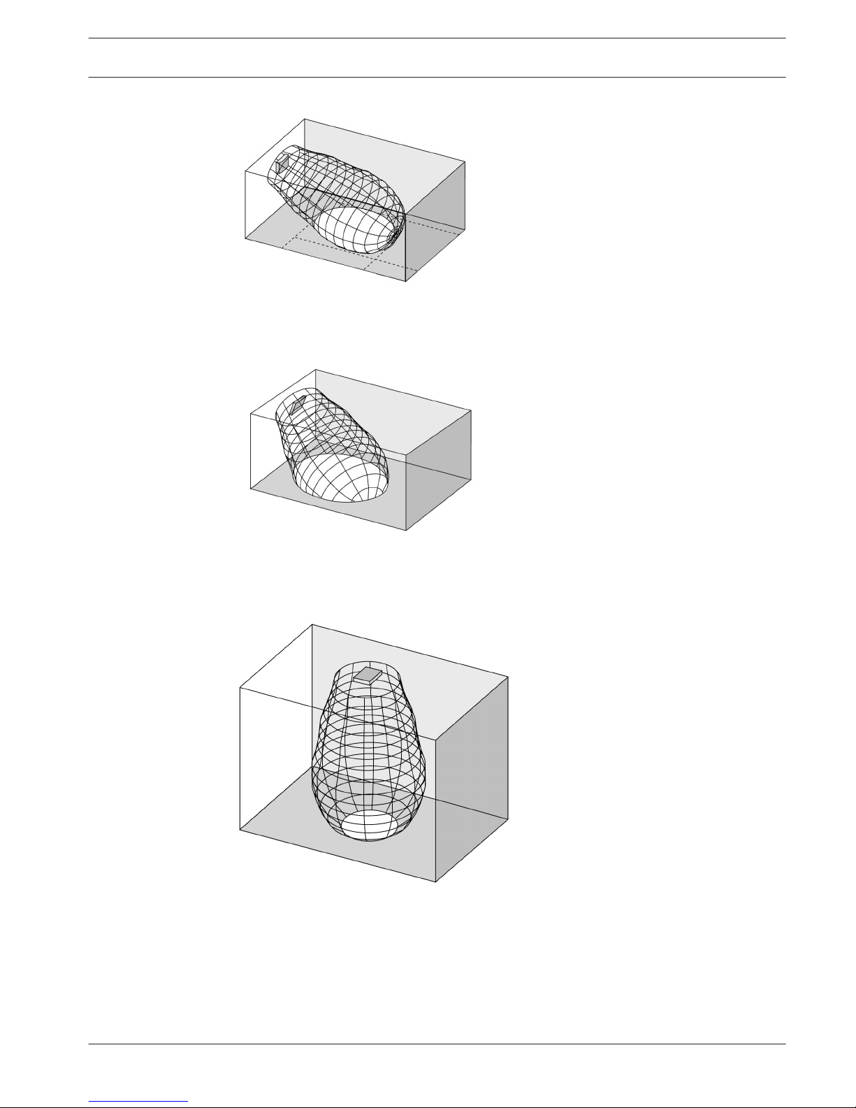
Figure 4.6: The radiator mounted at 15° to the ceiling
Figure 4.7: The radiator mounted at 45° to the ceiling
Figure 4.8: The radiator mounted perpendicular (at 90°) to the ceiling
Ambient lighting
The Integrus system is practically immune for the effect of ambient lighting. Fluorescent lamps
(with or without electronic ballast or dimming facility), such as TL lamps or energy saving
lamps give no problems with the Integrus system. Also sunlight and artificial lighting with
4.2.3
Language Distribution System Planning | en 25
Bosch Security Systems B.V. Operation manual 2013.11 | V1.4 |
incandescent or halogen lamps up to 1000 lux give no problems with the Integrus system.
When high levels of artificial lighting with incandescent or halogen lamps, such as spotlights or
stage lighting are applied, you should directly point a radiator at the receivers in order to
ensure reliable transmission. For venues containing large, unscreened windows, you must plan
on using additional radiators. For events taking place in the open air a site test will be
required in order to determine the required amount of radiators. With sufficient radiators
installed, the receivers will work without errors, even in bright sunlight.
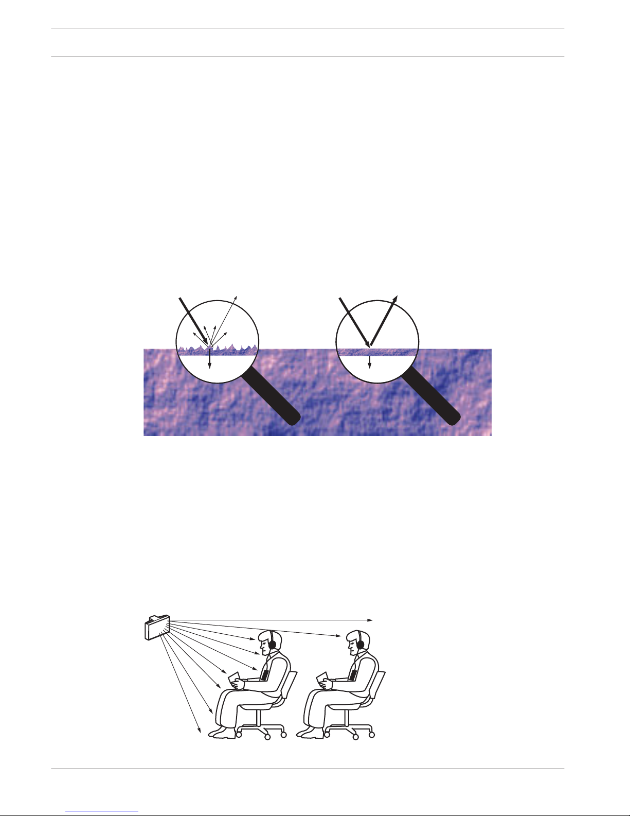
Objects, surfaces and reflections
The presence of objects in a conference venue can influence the distribution of infrared light.
The texture and color of the objects, walls and ceilings also plays an important role. Infrared
radiation is reflected from almost all surfaces. As is the case with visible light, smooth, bright
or shiny surfaces reflect well. Dark or rough surfaces absorb large proportions of the infrared
signal (see the next figure). With few exceptions it cannot pass through materials that are
opaque to visible light.
100% 40% 100% 80%
Figure 4.9: The texture of the material determines how much light is reflected and how much is absorbed
Problems caused by shadows from walls or furniture can be solved by ensuring that there are
sufficient radiators and that they are well positioned, so that a strong enough infrared field is
produced over the whole conference area. Care should be taken not to direct radiators
towards uncovered windows, as most of this radiation will subsequently be lost.
Position the radiators
Since infrared radiation can reach a receiver directly and/or via diffused reflections, it is
important to take this into account when considering the positioning of the radiators. Though
it is best if receivers pick up direct path infrared radiation, reflections improve the signal
reception and should therefore not be minimized. Radiators should be positioned high enough
not to be blocked by people in the hall (see the next two figures).
Figure 4.10: Infrared signal blocked by a person in front of the participant
4.2.4
4.2.5
26 en | Planning Language Distribution System
2013.11 | V1.4 | Operation manual Bosch Security Systems B.V.
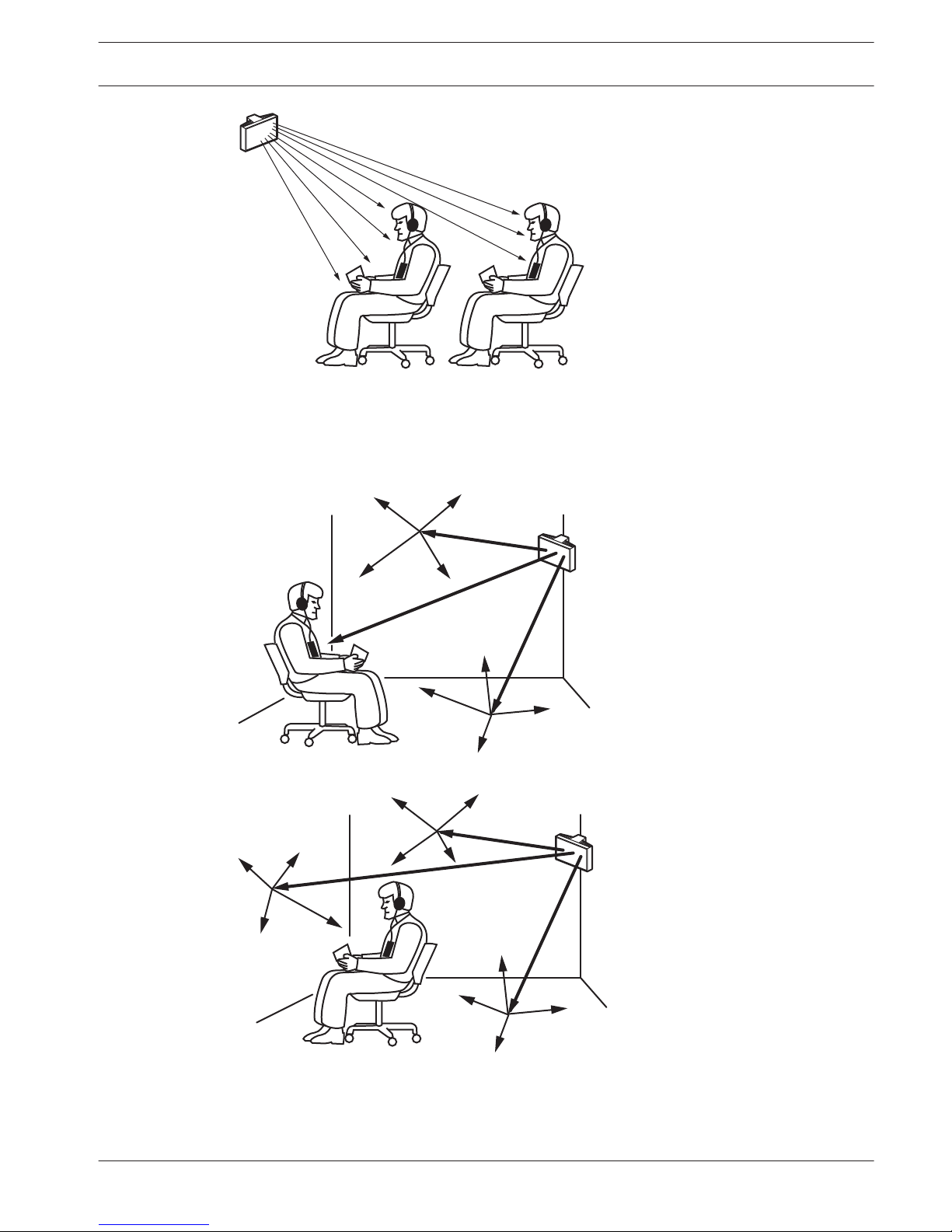
Figure 4.11: Infrared signal not blocked by a person in front of the participant
The figures below illustrate how infrared radiation can be directed to conference participants.
In figure 4.12, the participant is situated clear from obstacles and walls, so a combination of
direct and diffused radiation can be received. Figure 4.13 shows the signal being reflected
from a number of surfaces to the participant.
Figure 4.12: Combination of direct and reflected radiation
Figure 4.13: Combination of several reflected signals
For concentrically arranged conference rooms, centrally placed, angled radiators located high
up can cover the area very efficiently. In rooms with few or no reflecting surfaces, such as a
darkened film-projection room, the audience should be covered by direct path infrared
Language Distribution System
Planning | en 27
Bosch Security Systems B.V. Operation manual 2013.11 | V1.4 |
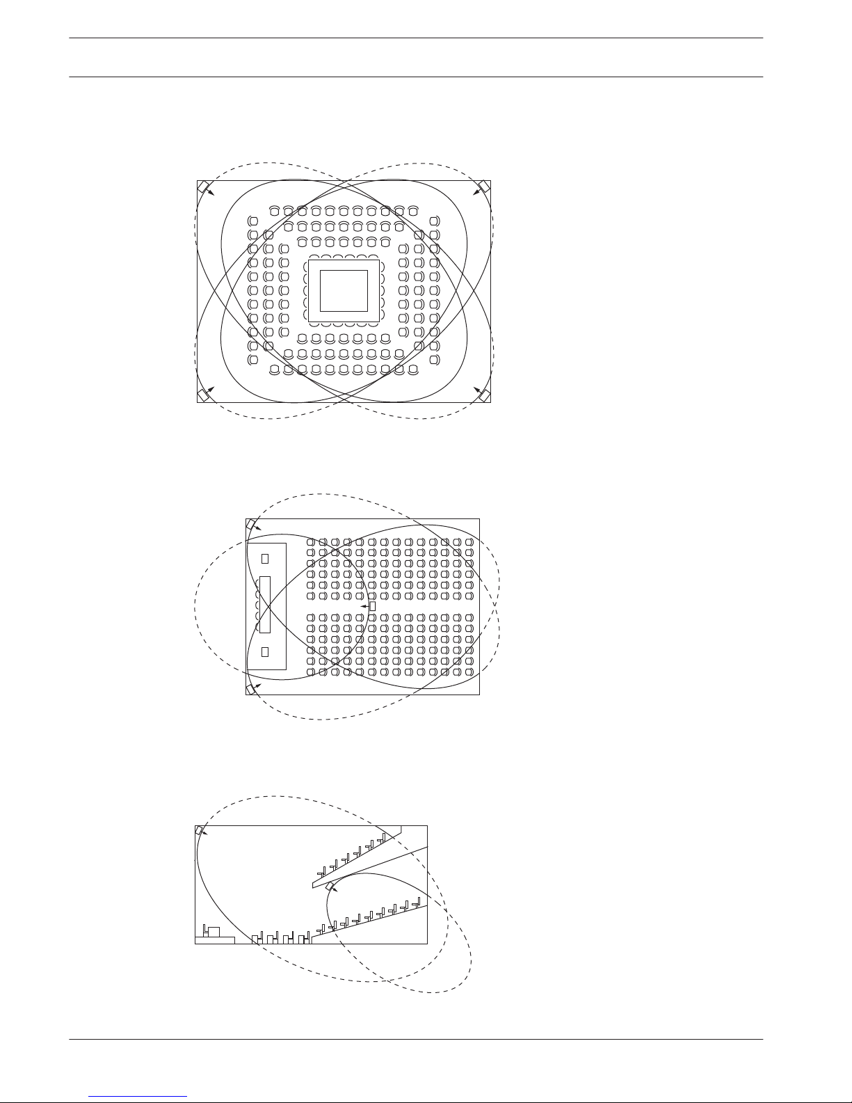
radiation from radiators positioned in front. When the direction of the receiver changes, e.g.
with varying seat arrangements, mount the radiators in the corners of the room (see the next
figure).
Figure 4.14: Radiator position for covering seats in a square arrangement
If the audience is always directed towards the radiators, you do not need radiators at the back
(see the next figure).
Figure 4.15: Radiator positioning in a conference hall with auditorium seating and podium
If the path of the infrared signals is partially blocked, e.g. under balconies, you should cover
the 'shaded' area with an additional radiator (see the next figure).
Figure 4.16: Radiator for covering seats beneath a balcony
28
en | Planning Language Distribution System
2013.11 | V1.4 | Operation manual Bosch Security Systems B.V.
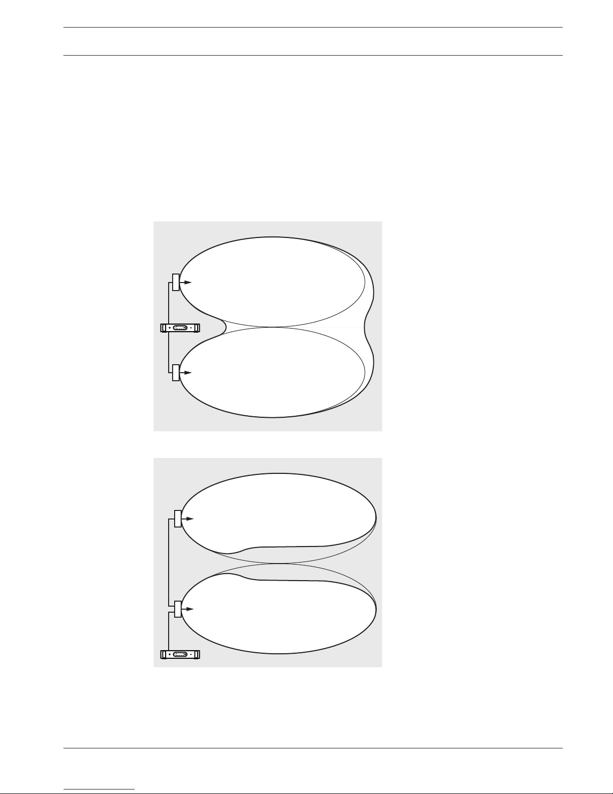
Overlapping footprints and black spots
When the footprints of two radiators partly overlap, the total coverage area can be larger than
the sum of the two separate footprints. In the overlap area the signal radiation power of two
radiators are added, which increases the area where the radiation intensity is larger than the
required intensity. However, differences in the delays of the signals picked up by the receiver
from two or more radiators can result in that the signals cancel each other out (multi path
effect). In worst-case situations this can lead to a loss of reception at such positions (black
spots).
The next two figures illustrate the effect of overlapping footprints and differences in signal
delays.
Figure 4.17: Increased coverage area caused by added radiation power
Figure 4.18: Reduced coverage area caused by differences in cable signal delay
The lower the carrier frequency, the less susceptible the receiver is for differences in signal
delays. The signal delays can be compensated by using the delay compensation switches on
the radiators (see section Determine the radiator delay switch positions, page 60).
4.2.6
Language Distribution System Planning | en 29
Bosch Security Systems B.V. Operation manual 2013.11 | V1.4 |
 Loading...