

Page 1
KTS 200
d e
Betriebsanleitung
Systemtester für die Steuergeräte-Di-
a gn o se
e n
Instruc tio n m anual
System tester fo r c o n tro l un it dia gn o -
sis
f r
Instruc tio ns d ‘em p lo i
T esteur systè me p o ur dia gn o stic des
c en tra les de c o mma n de
e s
Instruc c io nes d e m anejo
C o mp ro b a do r del sistema p a ra dia gn ó -
stic o de un ida des de c o n tro l
it
M anuale d ‘istruz io ni
T ester di sistema p er la dia gn o si delle
c en tra lin e di c o ma n do
s v
Bruk sanvisning
Systemtester fö r styrdo n sdia gn o s
p t
M anual d e serviç o
A p a relh o de teste do sistema p a ra a
dia gn o se de un ida des de c o ma n do
p l
Instruk c ja o bstugi
tester systemu do dia gn o styk i stero w -
n ik ó w
c s
N á v o d k o bsluz e
Systé mo v ý tester p ro dia gn o stik u
rídic íc h jedn o tek
t r
K ullanm a talim ati
K o n tro l ün iteleri a riz a tesh is islemi iç in
sistem test c ih a z i
Page 2

Bosch Diagnostics 1 689 989 001 2007-05-30|
Contents | KTS 200 | 15 | 15
1. Symbols Used 16
2. User instructions 16
2.1 Important notes 16
2.2 Safety instructions 16
2.3 Disposal 16
2.4 Electromagnetic compatibility (EMC) 16
2.5 Open Source software 16
3. Product description 17
3.1 Application 17
3.2 Requirements 17
3.2.1 Hardware 17
3.2.2 Software 17
3.3 Delivery specification 17
3.4 Special accessories 17
3.5 Device description 18
3.6 Selection and function keys 18
3.7 Wall bracket 19
4. Initial startup 19
4.1 Connection 19
4.2 Licensing with ESI[tronic] Startcenter 19
4.2.1 Installing ESI[tronic]
Startcenter from DVD 19
4.2.2 Starting the KTS 200 20
4.2.3 Licensing the KTS 200 by fax 21
4.2.4 Performing KTS 200 fax licensing 21
4.2.5 Online KTS 200 licensing 21
5. Operation 23
5.1 Connection to the vehicle 23
5.2 Turning on 23
5.3 Turning off 23
5.4 Program description 23
5.5 Software update 24
5.5.1 Software update using
the ESI[tronic] Startcenter DVD 24
5.5.2 Online software update 24
5.6 Faults 24
6. Maintenance 25
6.1 Cleaning 25
6.2 Spare and wearing parts 25
7. Technical data 25
7.1 General data 25
7.2 Interface protocols 25
7.3 Power pack 25
en
Contents
Page 3
Bosch Diagnostics1 689 989 001 2007-05-30|
16 | KTS 200 | Symbols Used
1. Symbols Used
Pictograms linked with the key words Danger, Warning
and Caution are warnings and always indicate an immediate or potential hazard to the user.
Danger
Immediate danger that could cause serious
personal injury or death.
Warning
Potentially dangerous situation that could
cause serious personal injury or death.
Caution
Potentially dangerous situation that could
cause personal injury or damage to property.
Important – warns of a potentially hazardous situation in which the product, the test sample or other
object in the vicinity could be damaged.
In addition to these warnings, the following symbols are
also used:
Info – In addition to these warnings, the following
symbols are also used.
Single-step procedure – instructions for a procedure
that can be completed in just one step.
Intermediate result – an intermediate r esult is
displayed during a procedure.
Final result – the final result is displayed at the end
of the procedure.
0
?
G
2. User instructions
2.1 Important notes
Important notes on the agreement pertaining to copyright, liability and warranty, about the user group and
obligation on the part of the contractor, are available
in the separate instructions entitled "Important notes"Important notesImportant notes
and safety instructions on Bosch Test Equipment".Bosch Test Equipment"..
These are to be read thoroughly before using, connecting and operating the product and they must be
observed.
2.2 Safety instructions
All safety instructions are available in the separate instructions "Important notes and safety instructions“ on"Important notes and safety instructions“ onImportant notes and safety instructions“ on
Bosch Test Equipment". These are to be read thorough-. These are to be read thoroughly before using, connecting and operating the product
and they must be observed.
2.3 Disposal
This product is subject to European guidelines 2002/96/EG (WEEE).
Old electrical and electronic devices, including
cables and accessories or batteries must be
disposed of separate to household waste.
Please use the return and collection systems in place for disposal in your area.
Damage to the environment and hazards to
personal health are prevented by properly
disposing of old equipment.
2.4 Electromagnetic compatibility (EMC)
This product is a product of Class A as under
EN 61 326.
This product can cause radio interference in the
home; in this case the operator may be asked to
implement appropriate measures.
0
2.5 Open Source software
An overview of the Open Source software licenses for
the KTS 200 is available on the "ESI[tronic] Startcenter"
DVD as an Adobe PDF document.
en
Page 4

Bosch Diagnostics
1 689 989 001 2007-05-30|
Product description | KTS 200 | 17 | 17
3. Product description
3.1 Application
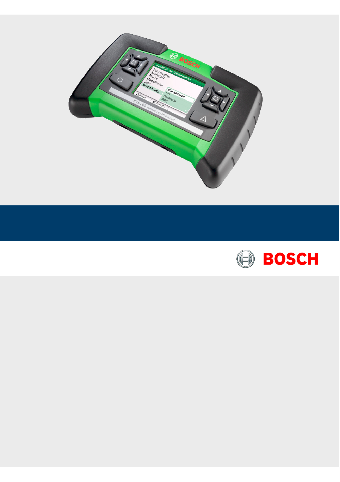
The KTS 200 is a system tester for control unit diagnosis
in vehicle workshops. The KTS 200 features licensed
control unit diagnosis software and has the following
functions:
Error memory reading
Actual value display
Actuator initiation
Use of control unit specific functions
The KTS 200 is a precision device and must not be
exposed to the effects of heat (e.g. direct sunlight),
impacts or vibration, magnetic fields or excessive
levels of dirt.
3.2 Requirements
3.2.1 Hardware
To license the KTS 200 ESI[tronic] software and perform the software update for KTS 200 control unit
diagnostics, a PC/laptop with the operating system
WIN 2000, WIN XP (SP2) or WIN Vista and at least one
free USB port is required. The USB port must support
the USB 2.0 protocol – USB 1.x protocols are not supported.
To license the KTS 200 ESI[tronic] software and update
the KTS 200 control unit diagnosis software, a PC/laptop
with the WIN XP or Windows Vista operating system and
at least one free USB port is required.
The KTS 200 may not be opened. Opening the
KTS 200 erases its licensing data. It is then no longer
possible to perform control unit diagnosis.
3.2.2 Software
The control unit diagnosis software on the KTS 200 must
be activated using the ESI[tronic] software license key.
R
R
R
R
3.3 Delivery specification
Description Order number
KTS 200
Power pack
Power supply lead
1 687 022 889
1 684 461 106
USB connecting lead, 1 m 1 684 465 491
OBD diagnostic lead, 1.5 m 1 684 465 555
DVD ESI[tronic] Startcenter 1 987 P12 005
Case 1 685 438 019
Connecting lead for
cigarette lighter socket (12 V)
1 684 465 584
Important information and safety instructions 1 689 979 922
KTS 200 operating instructions 1 689 989 001
Set of leads
<)
1 687 001 855
Set of leads
<)
1 687 001 875
Wall bracket
<)
1 681 320 082
<)
In some cases, special accessory only
Always store the KTS 200 and accessories in the
case when not in use.
3.4 Special accessories
Information on special accessories, such as vehiclespecific connecting leads, can be obtained from your
authorized Bosch dealer.
en
Page 5

Bosch Diagnostics1 689 989 001 2007-05-30|
18 | KTS 200 | Product description
3.5 Device description
The KTS 200 is a modular, portable diagnostic system
for control unit diagnosis that can be used anywhere.
The KTS 200 contains a computer unit with memory
card and a 3.5 inch LCD display. The KTS 200 control
unit diagnosis software is pre-installed on the memory
card in the factory.
The selection and function keys located next to the LCD
display are used to operate the unit.
The KTS 200 and the accessories are housed in a
protective case.
US
B
15V
D
C
KTS
200
Pow
ered by
ESI
[tronic]
B
O
S
C
H
459804/5K
o
1
4
6
5
4
3
2
3
Fig. 1: KTS 200
1 OBD diagnostic lead connection
2 LCD display
3 Selection keys
4 Function keys
5 Power pack connection
6 USB connection
3.6 Selection and function keys
The selection and function keys are assigned various
functions in the control unit diagnosis software. The
functions of the keys are specified in the soft key bar in
the control unit diagnosis software at each step in the
program.
The selection keys with the left and right arrow symbols
allow you to open and close selection lists.
The selection keys with the up and down arrow symbols
allow you to select one of the options in an open selection list (holding down a selection key automatically
scrolls through the options).
The selection keys located to the right and left of the
LCD display perform the same functions.
0
en
Page 6

Bosch Diagnostics 1 689 989 001 2007-05-30|
Product description | KTS 200 | 19 | 19
4. Initial startup
4.1 Connection
Before starting up for the first time, make sure that
the mains voltage matches the voltage specified on the
power pack (use power supply lead supplied).
The German power supply lead is included with
the unit.
4.2 Licensing with ESI[tronic]
Startcenter
Before you can use the KTS 200 to perform control unit
diagnosis, you must install the “ESI[tronic] Startcenter”
software on a PC/laptop and then license the KTS 200.
Do not connect the KTS 200 to the PC/laptop until
prompted to do so during the installation routine.
4.2.1 Installing ESI[tronic] Startcenter from DVD
Procedure:
Insert the “ESI[tronic] Startcenter” DVD in the DVD
drive (e.g. “D:\”) on the PC/laptop.
Open the “Run” input window (select “Start >>
Run...” in the taskbar).
Enter D:\setup.exe and confirm by
clicking <OK>.
The Setup routine is started.
4. Select the installation language and confirm
with <OK>.
The installation language selected will also be the
language used in ESI[tronic] Startcenter.
5. Follow the installation instructions on the screen.
In the “Country selection” installation menu, you
must select the country in which the KTS 200 will
be operated.
0
1.
2.
3.
?
0
0
3.7 Wall bracket
The KTS 200 can be hooked onto the wall bracket
(special accessory in some cases) for storage.
Attach the wall bracket at the desired location using
the 2 screw anchors and 2 wood screws supplied.
4598044
K
TS
2
00
P
o
w
er
edb
y
ESI
[
troni
c]
B
O
S
C
H
33 mm
Fig. 2: Wall bracket assembly
en
Page 7

Bosch Diagnostics1 689 989 001 2007-05-30|
20 | KTS 200 | Initial startup
The first time you connect the KTS 200 to the
PC/laptop, the USB driver installation in the Windows operating system must not be carried out. The
ESI[tronic] Startcenter installation routine automatically installs the USB driver that enables the KTS 200
to communicate with the PC/laptop.
If the Adobe Reader software is not yet installed on
the PC/laptop, it will be installed at the end of the
ESI[tronic] Startcenter installation routine. Adobe
Reader is required to display the logs from KTS 200
control unit diagnosis on the PC/laptop.
6. When installation is complete, restart the computer.
Windows is shut down and ESI[tronic]
Startcenter is restarted.
7. License the KTS 200 either by fax or online.
The “Help >> Help” menu opens up the online help.
Here, you will find all of the important information
about ESI[tronic] Startcenter.
0
?
0
4.2.2 Starting the KTS 200
Connect the KTS 200 to the mains using the power
pack supplied.
The KTS 200 starts up.
When turned on for the first time, the KTS 200
always starts in English.
If you want to use an alternative language on the
KTS 200, select it under “Menu >> Settings >>
Language”.
Connect the KTS 200 to the PC using the USB
connecting lead.
The KTS 200 waits for licensing to be completed.
1.
?
0
2.
3.
?
en
Page 8

Bosch Diagnostics 1 689 989 001 2007-05-30|
Initial startup | KTS 200 | 21 | 21
4.2.3 Licensing the KTS 200 by fax
In Startcenter, select “Licensing >> Fax” in the
menu.
The “License request” input window is opened.
Step 1: Enter your company data.
Step 2: Select the country for the license request.
Step 3: Enter the ID number and print out the
licensing form.
Sign the licensing form and return it by fax.
4.2.4 Performing KTS 200 fax licensing
Once you have received the license key by fax, you need
to perform the actual licensing.
Connect the KTS 200 to the mains using the power
pack supplied.
The KTS 200 starts up.
Connect the KTS 200 to the PC using the USB
connecting lead.
In Startcenter, click on “Licensing >> Perform
licensing” in the menu.
The “Perform license request” input window
is opened.
Enter the customer number, ID number and
license key.
Perform licensing.
The license key is transferred.
If licensing is successful, the KTS 200 is
restarted.
The KTS 200 is now licensed and you can perform
control unit diagnosis.
1.
?
2.
3.
4.
5.
1.
?
2.
3.
?
4.
5.
?
?
G
4.2.5 Online KTS 200 licensing
Online licensing can only be performed on a PC with
Internet access.
Connect the KTS 200 to the mains using the power
pack supplied.
The KTS 200 starts up.
Connect the KTS 200 to the PC using the USB
connecting lead.
In Startcenter, select “Licensing >> Online” in the
menu.
The “Online” input window is opened.
Step 1: Enter the customer number / password and
select <Login>.
The Internet connection for online licensing is
established.
If “Login” is not possible, check your proxy
settings under “Settings >> User settings”.
1.
?
2.
3.
?
4.
?
0
en
Page 9

Bosch Diagnostics1 689 989 001 2007-05-30|
22 | KTS 200 | Initial startup
Step 2: Select the contract ID and then select
<Generate>.
The license key is requested.
The request for the license key can take several
seconds.
While the license key is being transferred, the
USB connection and the power supply to the
KTS 200 may not be broken.
<Select <Execute>.
The license key is transferred to the KTS 200.
If licensing is successful, the KTS 200 is
restarted.
5.
?
0
6.
?
?
The KTS 200 is now licensed and you can perform
control unit diagnosis.
G
en
Page 10

Bosch Diagnostics 1 689 989 001 2007-05-30|
Operation | KTS 200 | 23 | 23
5. Operation
5.1 Connection to the vehicle
The KTS 200 is designed for operation on a vehicle
with a battery voltage of 12 Volts and 24 Volts.
Make sure that the OBD diagnostic lead is correctly
plugged into the KTS 200 and securely screwed
in. If incorrectly plugged in, the pins on the male
connector may bend or be broken off. Only use the
OBD diagnostic lead supplied.
1
2
3
4
5
6
7
8
9
10
11
12
13
14
15
16
1
3
5
2
U
SB
15VD
C
KTS 20
0
Pow
e
red by ESI[
tronic]
B
O
S
C
H
459804/3Ko
4
6
7
Fig. 3: KTS 200 connection schematic
1 OBD diagnostic socket in vehicle
2 OBD diagnostic lead
3 UNI connecting lead (special accessory)
4 KTS 200
5 Power pack
6 Connecting lead for cigarette lighter socket
7 USB connecting lead
When placing the KTS 200 on the steering
wheel, there is a risk of injury due to
triggering of the airbag.
The connection to the diagnostic interface in the
vehicle is made via
the OBD diagnostic lead (Fig. 3, item 2) or
the OBD diagnostic lead and also the UNI connecting
lead (Fig. 3, item 3; special accessory) or
the OBD diagnostic lead and a vehicle-specific
adapter lead (special accessory) or
a vehicle-specific adapter lead (special accessory).
5.2 Turning on
The KTS 200 is normally supplied with power by the
OBD diagnostic socket in the vehicle. If the position of
the OBD diagnostic socket in the vehicle is not known,
we recommend connecting the KTS 200 to the cigarette
lighter socket using the connecting lead and searching
for the OBD diagnostic socket using the KTS 200
control unit diagnosis software.
On some vehicles, the cigarette lighter socket only
supplies power when the ignition is turned on.
In test steps that require the engine to be started,
the battery voltage may drop to a point at which the
supply from the vehicle is no longer guaranteed. In
these cases, it may be necessary to use the power
pack to supply the KTS 200 with power.
On some vehicles, the power supply may only be
present on the OBD interface when the ignition has
been turned on.
If the KTS 200 is connected to a PC/laptop using the
USB connecting lead, the KTS 200 power supply must
come from the power pack supplied.
5.3 Turning off
The KTS 200 is always turned off when the OBD
diagnostic lead, the power pack or the connecting lead
for the cigarette lighter socket are not connected.
5.4 Program description
The online help for the KTS 200 control unit diagnosis software is opened under “Menu >> Help” in the soft key bar.
Basic information about the KTS 200 and ESI[tronic]
Startcenter can be found under “ESI[tronic] trainer” in
the ESI[tronic] Startcenter software.
R
R
R
R
0
0
0
en
Page 11

Bosch Diagnostics1 689 989 001 2007-05-30|
24 | KTS 200 | Operation
5.5 Software update
The software update is either performed using the
“ESI[tronic] Startcenter” DVD or “online”.
The online software update (section 5.5.2) can only
be performed with ESI[tronic] Startcenter version
2007/3 or later.
5.5.1 Software update using the ESI[tronic]
Startcenter DVD
Insert the “ESI[tronic] Startcenter” DVD in the DVD
drive (e.g. “D:\”) on the PC/laptop.
Open the “Run” input field (select “Start >> Run...”
in the taskbar).
Enter D:\setup.exe and confirm by
clicking <OK>.
The Setup routine is started.
Follow the installation instructions on the screen.
When installation is complete, restart the computer.
Windows is shut down and ESI[tronic]
Startcenter is restarted.
Connect the KTS 200 to the PC using the USB connecting lead.
Connect the KTS 200 to the mains using the power
pack supplied.
The KTS 200 starts up.
During the software update, the USB connection
and the power supply to the KTS 200 may not be
broken.
ESI[tronic] Startcenter: Open “KTS 200 >> Device
information”.
Select an available update.
Select <Update>.
The system software is installed on the KTS 200.
0
1.
2.
3.
?
?
4.
?
5.
6.
?
7.
8.
9.
G
5.5.2 Online software update
Start “ESI[tronic] Startcenter”.
Open the “Settings >>Online updates” input
window.
Enter the customer number and password and
select <Next>.
If “Login” is not possible, check your proxy
settings under “Settings >> User settings”.
Select an available update and start the software
update.
Follow the installation instructions on the screen.
When installation is complete, restart the computer.
Windows is shut down and ESI[tronic]
Startcenter is restarted.
Connect the KTS 200 to the PC using the USB
connecting lead.
Connect the KTS 200 to the mains using the power
pack supplied.
The KTS 200 starts up.
During the software update, the USB connection
and the power supply to the KTS 200 may not
be broken.
ESI[tronic] Startcenter: “KTS 200 >> Device
information”.
Select an available update
Select <Update>.
The system software is installed on the KTS 200.
5.6 Faults
The KTS 200 may not be opened. Opening the
KTS 200 erases its licensing data. It is then no
longer possible to perform control unit diagnosis.
No communication with the control unit
The fault message “No system found” appears during
control unit diagnosis.
Possible causes What can you do?
Incorrect lead
connected.
Check whether the correct
lead has been used.
Incorrect pin selected
in pin selection menu
Under “Start >> Diagnostic socket”,
check which pin has to be used.
If problems of a different nature occur, please
contact the ESI[tronic] service hotline directly.
1.
2.
3.
0
4.
5.
6.
?
7.
8.
?
9.
10.
11.
G
0
en
Page 12

Bosch Diagnostics 1 689 989 001 2007-05-30|
Maintenance | KTS 200 | 25 | 25
6. Maintenance
6.1 Cleaning
The housing and the display on the KTS 200 may only
be cleaned with soft cloths and with neutral cleaning
agents. Do not use any abrasive cleaning agent or rough
cleaning cloths.
6.2 Spare and wearing parts
Description Order number
System tester KTS 200 (green) 1 687 023 279
System tester KTS 200 (blue) 1 687 023 428
System tester KTS 200 (gray) 1 687 023 429
Power pack
Power supply lead
(<)
1 687 023 889
1 684 461 106
USB connecting lead, 1 m
(<)
1 684 465 491
OBD diagnostic lead, 1.5 m
(<)
1 684 465 555
Wall bracket 1 681 320 082
(<)
Wearing parts
7. Technical data
7.1 General data
Property Value/Range
Operating voltage 7 VDC — 34 VDC
Power consumption approx. 7 Watt
LCD display 3,5"
320 * 240 Pixel
Dimensions (L x W x H) 140 x 220 x 40 mm
Weight (without connecting leads) 600 g
Operating temperature 5 °C – 40 °C
Relative humidity 90 % (at 25 °C)
Protection class IP 30
7.2 Interface protocols
The following interfaces and their associated protocols
are supported for control unit diagnosis in compliance
with ISO 15031:
ISO 9141-2 (communication lines K and L)
SAE J1850VPW und SAE J1850PWM
(communication lines BUS+ and BUS-)
CAN ISO 11898 ISO 15765-4 (OBD)
(communication lines CAN-H and CAN-L)
CAN Single Wire
CAN Low Speed
7.3 Power pack
Property Value/Range
Input voltage 90 VAC — 264 VAC
Input frequency 47 Hz — 63 Hz
Output voltage 15 V
Operating temperature 0 °C — 40 °C
R
R
R
R
R
en
 Loading...