

Page 1
1
2
3
4
10
9
8
7
6
5
Intrusion Alarm Systems | ICP-MAP5000-COM Intrusion panel, 8 loop, communicator
ICP-MAP5000-COM Intrusion panel, 8
loop, communicator
www.boschsecurity.com
u Up to 1500 addresses, 500 areas, and 996 users
u 8 supervised inputs and one unsupervised tamper
input
Using a Bosch Data Bus (BDB) based on Controller
Area Network (CAN) technology as the internal and
external bus, the panel supports a range of
applications as part of the scalable Modular Alarm
Platform 5000 system.
The panel mounts on the MAP Hinged Mounting Plate
in the MAP Panel Enclosure Kit. This provides easy
access to all wiring terminals and communication port
connectors.
u Two programmable outputs for optical and
acoustical signaling device as well as for other local
notification devices; two programmable relay
outputs; and one auxiliary output
u Two Bosch Data Bus (BDB) interfaces and Ethernet
port
u Event reporting via Ethernet (optional) and via
integrated IP Communicator
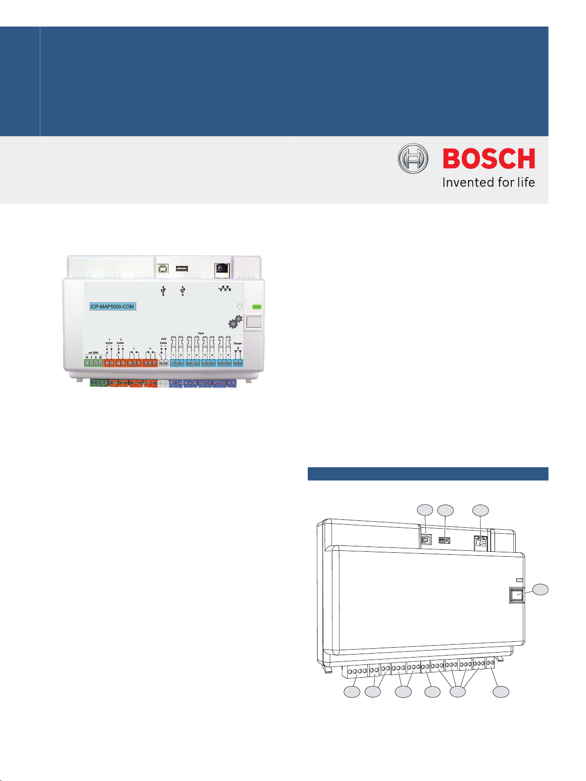
System overview
Terminals and connectors - front view
Page 2
1
2
2 | ICP-MAP5000-COM Intrusion panel, 8 loop, communicator
Element Description
1 USB host port – currently not enabled
2 USB port – currently not enabled
3 Ethernet port
4 Installer switch
5 Tamper switch input
6 Eight supervised inputs
7 Auxiliary power output
8 Two form C dry-contact relay ouputs
9 Two auxiliary switched voltage outputs
10 External Bosch Data Bus (BDB) port
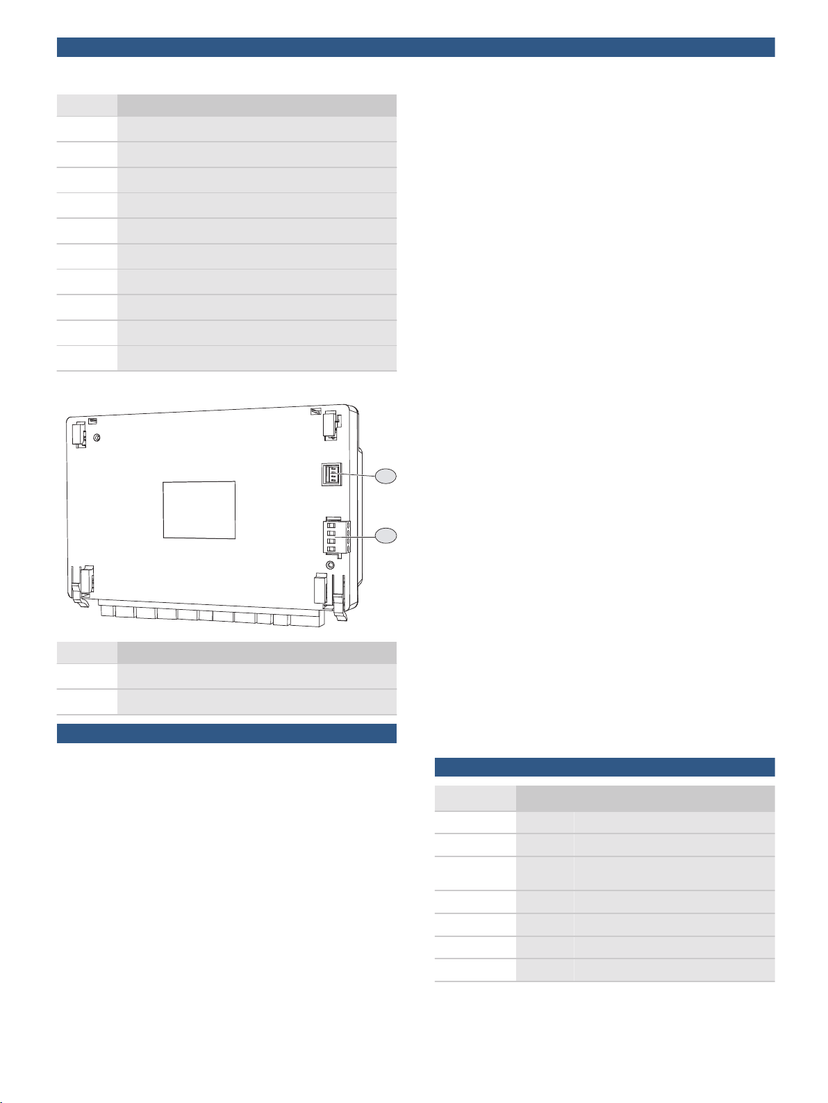
Terminals and connectors - back view
• External BDB –Up to 1000 m in total length, the
external BDB allows command centers, LSN
Gateways, CAN Splitter Modules and power supplies
to be placed at the point of use, promoting greater
efficiency.
Inputs and outputs
The panel supports one unsupervised tamper input
and eight supervised inputs. It also supports one
auxiliary output, two Form C dry-contact relay outputs,
and two programmable outputs for local notification
devices.
The auxiliary output and both power outputs are
over‑current protected. The outputs are designed to
provide individual protection. As a result, if a short
circuit occurs on one output, the fault does not
adversely affect the operation of another output.
Firmware upgrades
The firmware of all devices in the MAP system can be
upgraded or updated with the Bosch Remote
Programming Software (RPS). This allows for on‑site
or off‑site (IP through Ethernet) upgrades or updates.
Languages
For each user, a preferred language is selected when
the user is created. When the user logs in, the
preferred language is used at the command center.
Element Description
1 Power supply input connector
2 Internal Bosch Data Bus (BDB) port
Functions
The panel supports up to 1500 addresses, 500 areas,
and 996 users. As part of a Modular Alarm Platform
5000 solution, the panel connects to building
management systems through internet protocol (IP).
A VdS system is limited to two areas, when connecting
to the MAP control centers via the internal and
external Data Bus. More areas can be realized with
additional operating and display panels (one per area)
on the LSN bus or with additional control centers on
the external Data Bus using the CAN splitter module.
Bosch Data Bus (BDB) based on CAN technology
The panel provides two data buses:
• Internal BDB – Limited to 3 m in total length, the
internal BDB connects the panel to other MAP
devices.
Event reporting
Events can be transmitted via two separate paths
(Ethernet, GPRS) to a monitoring station.
Available protocols via integrated IP Communicator:
• VdS 2465-S2
• SIA DC-09 (TCP/IP and UDP/IP)
• Conettix IP
Communication with Bosch Software Packages
The MAP system allows separate communication with
the following:
• Management systems
• Bosch Remote Programming Software (RPS)
Programming and diagnostic software for control
panels that provides remote programming, record
storage, remote control, and diagnostics options.
Certifications and approvals
Region Regulatory compliance/quality marks
Germany VdS-S S 112016 [MAP 5000]
Austria VSOE W 160215/60 E, VSOE Class WS
Germany VdS G114801 ICP-MAP5000-COM ICP-
MAP5000-SC
VdS G111040 [ICP-MAP-5000]
VdS S 196602
VdS S 196001
Europe CE [MAP 5000 Modules]
Page 3

3 | ICP-MAP5000-COM Intrusion panel, 8 loop, communicator
Region Regulatory compliance/quality marks
EN50131EN-ST-000121 [MAP 5000]
France AFNOR 1230200016A1 ICP-MAP5000-COM
Parts included
Quantity Component
1 MAP panel 5000 COM
1 Accessory pack
• Eight 12.1 kΩ EOL resistors
• Two 120 Ω CAN terminal EOL resistors
• One panel power cable
• One 2-pin terminal plug (white)
• One 2-pin terminal plug (dark blue)
• Two 3-pin terminal plugs (orange)
• Four 3-pin terminal plugs (dark blue)
• One 4-pin terminal plug (green)
• Snap ferrite small
• Snap ferrite big
1 Literature, Operation Manual
1 Literature, Release Notes
Technical specifications
Electrical
Minimum operating voltage in
VDC
19
the batteries regarding local
regulations or EN standards if
needed.
Frequency bands of operation Power level for radio
equipment
GSM900 Class 4 (2W) - GPRS Class 10
GSM1800 Class 1 (1W) - GPRS Class 10
Mechanical
Dimension in cm (H x W x D) 14.6 x 21.6 x 5.5
Weight in g 450
Indicators Green LED for operating status
Number of output modules
Auxiliary output 1
Power output 2
Form C dry-contact relay output 2
Number of devices
LSN Gateways 8
Control Centers 32
Integrated IP Communicator 1
Environmental
Maximum operating voltage in
VDC
Rated voltage in VDC 28
Minimum current consumption inmA250
Maximum current consumption inmA500
On-board inputs
Maximum line resistance in Ω 100
Outputs
Maximum current consumption in
mA per output
Relay outoputs
Maximum operating voltage in
VDC
Maximum operating voltage in
VAC
Back‑up time Determined by battery capacity
29
1000
30
30
and system load. Consider time
or capacity limits for recharging
Minimum operating temperature
in °C
Maximum operating temperature
in °C
Minimum storage temperature in°C-20
Maximum storage temperature in°C60
Minimum relative humidity in % 5
Maximum relative humidity in % 95
Protection class IP30
Security level IK04
Environmental class II:
Usage Indoor
-10
55
IP31 (built into the MAP Panel
Enclosure with an edge
protection profile)
IK06 (built into the MAP Panel
Enclosure with an edge
protection profile)
EN50130-5, VdS 2110
Page 4

4 | ICP-MAP5000-COM Intrusion panel, 8 loop, communicator
Represented by:
Europe, Middle East, Africa: Germany: North America: Asia-Pacific:
Bosch Security Systems B.V.
P.O. Box 80002
5600 JB Eindhoven, The Netherlands
Phone: + 31 40 2577 284
emea.securitysystems@bosch.com
emea.boschsecurity.com
Bosch Sicherheitssysteme GmbH
Robert-Bosch-Ring 5
85630 Grasbrunn
Germany
www.boschsecurity.com
Bosch Security Systems, LLC
130 Perinton Parkway
Fairport, New York, 14450, USA
Phone: +1 800 289 0096
Fax: +1 585 223 9180
onlinehelp@us.bosch.com
www.boschsecurity.us
Robert Bosch (SEA) Pte Ltd, Security Systems
11 Bishan Street 21
Singapore 573943
Phone: +65 6571 2808
Fax: +65 6571 2699
apr.securitysystems@bosch.com
www.boschsecurity.asia
© Bosch Security Systems 2021 | Data subject to change without notice
15486384907 | en, V26, 01. Apr 2021
Ordering information
ICP-MAP5000-COM Intrusion panel, 8 loop, communicator
MAP panel 5000 with wiring terminals for tamper and
power supply inputs, eight supervised inputs form C
relay and auxiliary power outputs, switched voltage
outputs, two Bosch Data Bus ports and an Ethernet
port.
Suitable for 8 LSN Gateways and 32 Control Centers
(touch screen keypads).
Additional integrated IP Communicator.
Order number ICP-MAP5000-COM
Services
EWE-MAP5-IW 12mths wrty ext MAP5000 panel
12 months warranty extension
Order number EWE-MAP5-IW
 Loading...