

Bosch ICP-EZM2 Installer's Manual

Easy Series (ICP-EZM2)
EN
Installer Guide
Intrusion Control Panel

Easy Series (ICP-EZM2) | Installer Guide | Contents
Contents
1.0 Quick Reference .................................................... 3
1.1 System Overview .................................................3
1.2 Control Center Overview ...................................3
1.3 Basic Operation Information..............................4
1.4 System Setup (Wired and Wireless)..............5
1.5 Installer Phone Menu...........................................6
1.6 User Phone Menu ................................................7
2.0 Installation.................................................................8
2.1 Enclosure Installation (Step 1)..........................8
2.2 Control Panel Board Installation (Step 2)......9
2.3 Control Center Installation (Step 3) .............10
2.4 DX2010 Installation (Step 4).........................12
2.5 Wireless Hub Installation (Step 5)................13
2.6 Supervised Point Connections (Step 6) .....14
2.6.1 Fire Point Wiring........................................14
2.6.2 Intrusion Point Wiring...............................15
2.6.3 Keyswitch Wiring ......................................15
2.7 Programmable Output Connections (Step 7)
...............................................................................16
2.7.1 Programmable Output 1 Wiring............16
2.7.2 Programmable Outputs 2 to 4 Wiring.17
2.8 Phone Line Connections (Step 8) ................18
2.9 Insert Voice Module (Step 9).........................18
2.10 EZTS Connections (Step 10)........................18
2.11 Power Supply Installation (Step 11).............19
2.11.1 EZPS Wire-in Power Supply.................. 19
2.11.2 Plug-in Power Supply...............................21
2.11.3 12 VDC Standby Battery ........................21
2.12 Secure the Enclosure (Step 12) ...................22
2.13 Program the Control Panel (Step 13)..........22
2.14 Test the System (Step 14) .............................22
3.0 Point Expansion ...................................................23
3.1 Establishing the Wireless Network and
Configuring Wireless Devices .......................23
3.1.1 Discover New System..............................23
3.1.2 Establish and Configure the Wireless
Network .......................................................23
3.1.3 Configure Devices ....................................24
3.1.4 Test Devices...............................................24
3.2 Wireless Maintenance .....................................26
3.2.1 Wireless Configuration Menu ................ 26
3.2.2 Assigning Points 1 to 8 as Wireless
Points ...........................................................27
3.2.3 DX2010 Input Expanders and Wireless
Points ...........................................................27
3.2.4 Recovering the Wireless Network........27
3.3 Wireless System Messages...........................28
4.0 Programming ........................................................29
4.1 Enter Programming...........................................29
4.2 Basic Programming..........................................30
4.2.1 Points...........................................................31
4.2.2 Report Configuration................................32
4.2.3 Outputs ....................................................... 33
4.2.4 Country Code ............................................34
4.3 Expert Programming.........................................36
4.3.1 ROM Firmware Version Items................37
4.3.2 System Programming Items ................... 37
4.3.3 Communicator Programming Items......41
4.3.4 Report Routing Programming Items..... 43
4.3.5 Point Programming Items........................ 46
4.3.6 Output Programming Items ....................51
4.3.7 Control Center Programming Items ..... 52
4.3.8 User Programming Items.........................53
4.3.9 Factory Default ..........................................53
4.4 Exit Programming..............................................53
4.5 Programming Key..............................................54
4.6 Remote Programming Software (RPS) ....... 55
4.6.1 Installer Calls RPS....................................55
4.6.2 RPS Calls the Control Panel.................. 55
5.0 System Test...........................................................56
6.0 Maintenance ..........................................................56
7.0 Reference Materials...........................................57
7.1 Enclosure Wiring Label................................... 57
7.2 Power-limited Wire Routing ........................... 58
7.3 Standby Battery Calculation .......................... 59
7.4 Event Report Codes.........................................60
7.5 Display States....................................................62
7.6 Frequently Asked Questions (FAQ).............64
7.6.1 Programming Questions ......................... 64
7.6.2 System Operation Questions.................65
7.6.3 Control Center Questions ...................... 67
7.6.4 Passcode Questions................................ 67
7.7 Agency Approvals and Requirements..........68
7.7.1 Certifications and Approvals..................68
7.7.2 FCC..............................................................68
7.7.3 Industry Canada........................................ 69
7.7.4 SIA................................................................69
7.7.5 Underwriters Laboratories (UL) ............. 71
7.7.6 EN50131-1 ................................................ 72
7.7.7 PD6662 and DD243 Requirements .... 73
7.7.8 INCERT .......................................................73
7.7.9 cUL ...............................................................73
7.8 Specifications ....................................................74
7.9 Compatible Options.........................................76
2 Bosch Security Systems, Inc. | 5/07 | F01U025147-01
.
1.0 Quick Reference
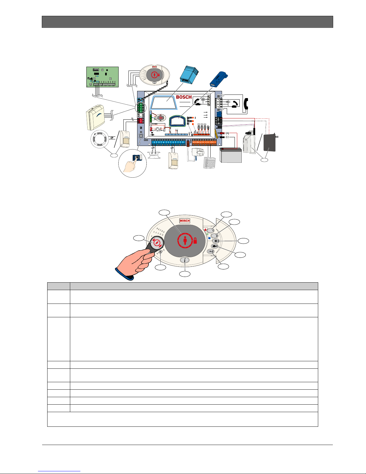
1.1 System Overview
Easy Series (ICP-EZM2) | Installer Guide | 1.0 Quick Reference
C =
C =12V
C =0V
NC
2345678
CNO
1
12 VDC
2
1
Connect either a two-wire smoke detector or an intrusion detector, such as a motion detector, to Point 1.
2
Use either the EZPS wire-in power supply or a transformer.
1.2 Control Center Overview
9
8
7
6
Callout Description
1
Press and hold [1] for two sec to start a fire alarm.
For an emergency alarm, press and hold [1] and [2] for two sec.
2 Press and hold [2] for two sec to start a panic alarm.
For an emergency alarm, press and hold [1] and [2] for two sec.
3 Press and hold [3] for 2 sec to enter User Menu, and then present token or enter passcode. Select an option1:
• Add User:
Press [1]. Use this option to add a new user. You must assign a passcode. You can
also record a description and assign a token or key fob. Follow all voice prompts.
• Change User:
Press [2]. Use this option to add or change the passcode, description, token, or key fob
assigned to an existing user. Follow all voice prompts.
• Delete User:
Press [3].
4 Press and hold [4] for 2 sec to turn Chime Mode on or off.
5
Press and hold [5] for 2 sec to enter Volume Menu, and then press again to select a level: low, medium, high, or
2
quiet
.
6 Press [i] to turn the system on or off. Follow all voice prompts.
7 Speak into the audio interface to talk to someone on the telephone during a two-way voice session.
8 Present token to control center to turn the system on or off.
9 Control center display. Refer to Section 7.5 Display States on page 62 for more information.
1
Master user token or passcode required to access these options. Other users can change only their own passcodes.
2
Quiet Control Center: Exit Delay and Entry Delay tones are silenced.
1
2
3
4
5
Bosch Security Systems, Inc. | 5/07 | F01U025147-01 3

Easy Series (ICP-EZM2) | Installer Guide | 1.0 Quick Reference
1.3 Basic Operation Information
Item Description
Press [#] three times, and enter a passcode.
Dial the house phone number, and press [*] three times when the call is
answered. Enter a passcode.
Connect a test telephone to the control panel’s test posts or telephone
terminals. Press and hold the system test button for approximately 15 sec. Enter
Start and end a
phone session
House phone:
Outside phone:
Installer quick connect:
a passcode.
End a phone session:
Press [#] repeatedly until the system says “goodbye.”
Start a phone session (refer to options above).
Enter installer passcode when prompted.
Enter and exit
programming
From the Installer Menu, press [3] for basic programming, or [4] for expert programming.
- For Basic Programming, refer to Section 4.2 on page 30.
- For Expert Programming, refer to Section 4.3 on page 36.
To exit programming, press [#] repeatedly until you hear the system announce the Installer Menu options.
Passcode length
Installer
passcode
Master user
passcode
Factory default
Add or change
users
System Test On the control panel board, press the System Test button once to start the System Test.
“Call for
Service” Details
Options are four digits or six digits. Selection affects all passcode lengths.
Expert programming →Expert Programming Item Number 861.
Four-digit default = 5432; six-digit default = 543211 (Expert Programming Item Number 7011).
Four-digit default = 1234; six-digit default = 123455. (Expert Programming Item Number 7001).
In expert programming, enter Expert Programming Item Number 9999. Doing this restores all factory default
values. All programming items, except for the country code, are reset when you restore the factory default
values. All recorded speech items are unaffected.
Start a phone session, or press and hold [3] on the control center (refer to Section 1.2 Control Center
Overview on page 3).
Enter the master user passcode.
Press [4] to select the User Menu.
Press [1] to add a new user, or press [3] to change an existing user. Follow all voice prompts.
When you add a new user or change an existing user, you can also assign a token or key fob.
Enter the installer passcode when you hear the “Call for Service” message.
The system announces the system trouble condition and then asks you to select a menu option.
4 Bosch Security Systems, Inc. | 5/07 | F01U025147-01
Easy Series (ICP-EZM2) | Installer Guide | 1.0 Quick Reference
.
1.4 System Setup (Wired and Wireless)
After the system is installed and configured, add key fobs when you add users.
Wireless support is not investigated by UL.
To install an Easy Series Intrusion Control Panel with wireless devices:
1. Follow all instructions in the wLSN Reference Guide (P/N: F01U009440) to verify adequate signal strength
exists at each device location.
2. Install all hard-wired devices, such as the control panel, control center, input and output devices, DX2010
Input Expanders, and the wireless hub.
Refer to the installation instructions supplied with each device for specific installation and configuration
instructions.
The control panel assigns wireless point numbers based on whether or not one or more DX2010
Input Expanders are connected to the control panel.
3. Install the bases for all wireless devices.
4. Apply power to the control panel.
5. Start the System Test:
- From Phone:
1. Start a phone session.
Refer to Section 1.3 Basic Operation Information on page 4 for instructions.
2. From the Installer Phone Menu, press [1] for System Maintenance.
3. Press [2] for Full System Test.
Refer to Section 1.5 Installer Phone Menu on page 6.
- From Control Panel: To start the full system test, press and hold the System Test button for one
second. Refer to Section 5.0 System Test on page 56 for more information.
6. When the system announces “Install all batteries,” install the batteries or remove the battery tabs from all
wireless devices. Mount the device covers on the bases.
7. When all batteries are installed and device covers are mounted, press [1] on the phone or control center to
continue.
The system identifies (discovers) new wireless devices on the system. This process takes up to 4 min to
complete. When the discovery process is complete, the system announces the number of devices
discovered.
8. When the system announces “Test all points,” test each device (fault and restore), including wireless inputs
and outputs.
Refer to Section 3.1.4 Test Devices on page 24 for more information.
Point numbers are assigned to wireless devices in the order that the devices are tested (tampered
or faulted and restored). If specific point numbers are preferred for wireless devices, ensure that the
wireless devices are tested in the appropriate order. Otherwise, the system assigns the lowest
available point number to the first tested wireless device.
9. As you test each device, complete Section 4.3.5 Point Programming Items on page 46, and Section 4.3.6 Output
Programming Items on page 51.
When you restore the device, the system announces the assigned device number.
Complete Sections 4.3.5 and 4.3.6 as you test the inputs and outputs. Otherwise, you cannot cross-reference
point numbers to point descriptions in the event of a point trouble.
The control panel completes the remaining system tests and notifies you when they are complete.
10. When the control panel completes all system tests, enter Basic Programming. You can also use RPS to
program the control panel.
Bosch Security Systems, Inc. | 5/07 | F01U025147-01 5
Easy Series (ICP-EZM2) | Installer Guide | 1.0 Quick Reference
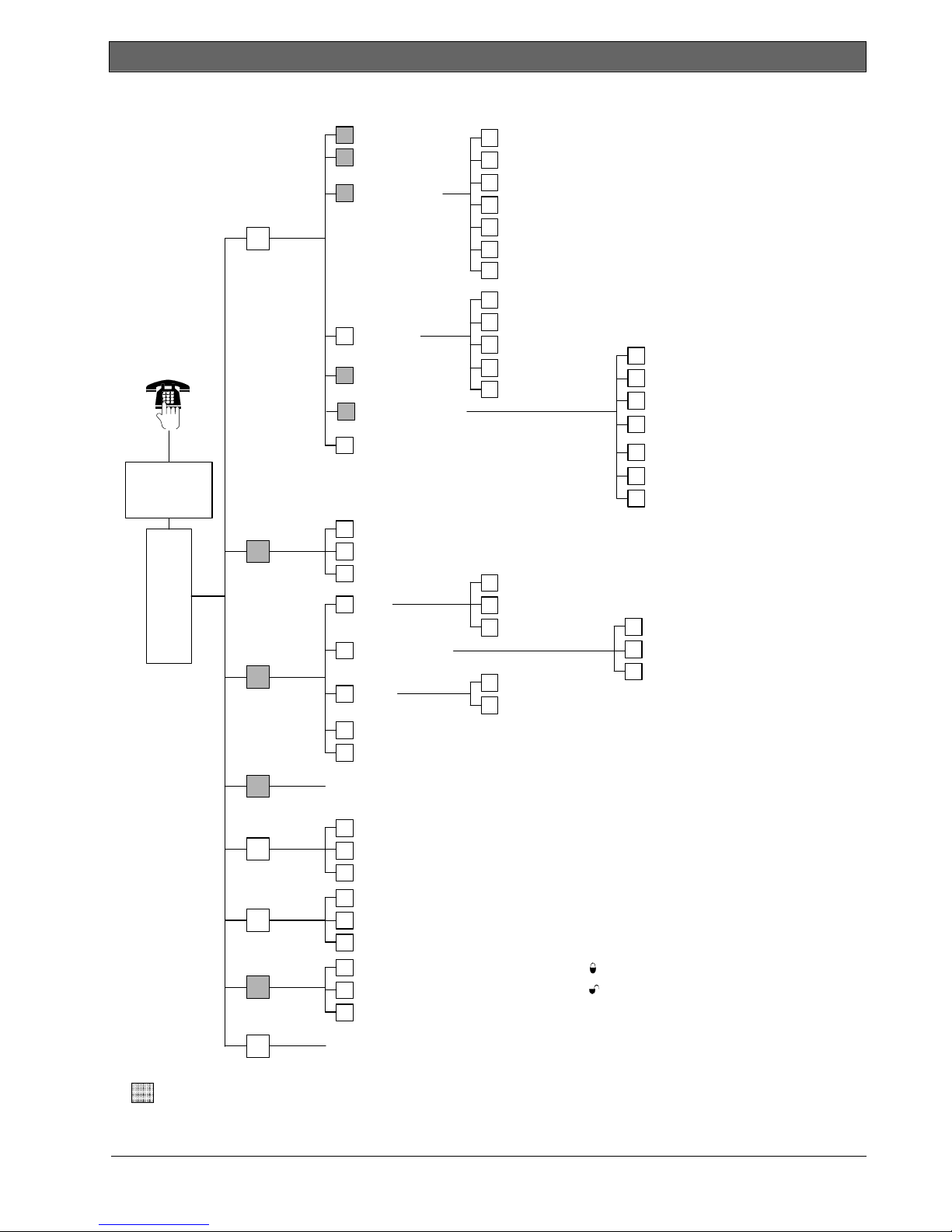
1.5 Installer Phone Menu
Installer passcode
4-digit default: 5432
6-digit default: 543211
1
System
Maintenance
1 Set date and time
Full system test
2
System test m enu
3
Event history
4
Reset system
5
6
Wireless configuration
Exit system maintenance
#
1
Warning device test
2
Battery test
Communication test
3
Control center test
4
Point test
5
Operate Outputs6
Exit system test menu
#
Most recent events
1
2
Events by date
Last alarm event
3
Last 10 events
4
Exit event history
#
1
Replace a device
Add a device
2
Delete a device
3
Transfer wireless data
4
(control panel-to-hub)
Transfer wireless data
5
(hub-to-control panel)
Erase and discover6
Exit Wireless configuration
#
Installer
Phone
Menu
2
User Menu
3
Basic
Programming
4
Expert
Programming
5
Two-Way
Voice Session
6
Custom
Messages
7
Programming
Key
Change installer passcode
1
Change master user (User 1) passcode
2
Exit user menu
#
1
Points
2
Report Configuration
3
Outputs
4
Country Code
#
Exit basic programming
Enter programming it em, enter selection.
1
Talk to person at control center
2
Listen to person at control center
End voice session
#
Record site description
1
Record call for service message
2
Exit custom mes sages
#
Send data from key to control panel (key position = )
1
Send data from control panel to key (key position = )
2
Exit programming key
#
Record point description
1
Set point type
2
Exit points
#
Select output function
1
Exit outputs
#
}
}
Enter account number
1
Configure report destinations
2
Exit report configuration
#
The voice session only lasts 90 seconds.
To reset the timer, press [1] on the phone during talk mode, or
[2] during listen mode.
Only the person on the phone can switch between talk and listen
modes.
Custom messages are stored in the voice module, and are not
saved with the control panel's programming data.
#
=
The system’s arming status (on or off) and Expert Programming Item Number 142’s setting of (0 or 1)
determines the availability of these menu items.
6 Bosch Security Systems, Inc. | 5/07 | F01U025147-01
Exit installer menu and end phone session.
Easy Series (ICP-EZM2) | Installer Guide | 1.0 Quick Reference
.
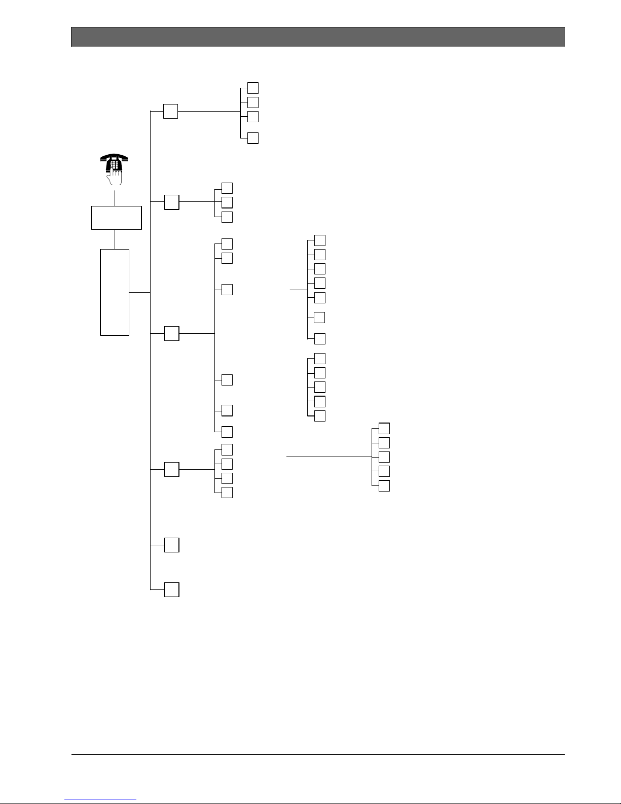
1.6 User Phone Menu
Turn system on and stay inside
1
Turn system on and leave
1
Turn System On or Off
Only use this option
on non-UL systems.
2
Enter user
1
passcode
Phone
Menu
1
Only a user passcode (Users 1 to 21) can access the User Menu.
2
If the system is on, the System Maintenance option is not available.
3
Only the master user can add, change, or delete users. Users 2 to 21 can only change their own passcodes.
Two-Way
Voice Session
3
System
Maintenance
4
User Menu
Only the Master User can
access the full User Menu.
Users 2 to 21 can only change
their own passcode.
5
Operate Outputs
To turn an output on or off, press the
corresponding number key on the phone.
#
Exit
End phone session.
2
3
2
3
Turn on custom protection
To hear this option, custom protection must be enabled.
# Exit
Talk to person at control center
1
2
Listen to person at control center
#
End voice session
1 Set date and time
2
Full system test
System test menu
3
Event history
4
5
Reset system
#
Exit
Add new user
1
2
Change user
3
Delete user
Exit
#
To add or change a user:
}
The voice session only lasts 90 seconds.
To reset the timer, press [1] on the phone during talk mode,
or [2] during listen mode.
}
Warning device test
1
2
Battery test
3
Communication test
4
Control center test
5
Point test
Operate outputs
OR
6
Expert Programming (Enable Installer Access)
Exit system test menu
#
Most recent events
1
2
Events by date
3
Last alarm event
4
Last 10 events
#
Exit
Change token
1
Record description
2
Change passcode
3
Change key fob
4
Exit
#
4
User voice descriptions are stored in the voice module and are not transferred to the control panel with
programming data.
4
Option 6 allows the master user (User 1) to enable the Installer Passcode. Refer to Expert Programming Item
Number 142 on page 39 for more information.
Availability of the menu items shown above depends on the system’s status.
Bosch Security Systems, Inc. | 5/07 | F01U025147-01 7
Easy Series (ICP-EZM2) | Installer Guide | 2.0 Installation
2.0 Installation
Only use authorized service personnel to install this system.
Because the control panel is permanently connected equipment, a readily accessible disconnect
To aid in system installation, this section is divided into sub-sections and labeled in a step-by-step format. Each
sub-section, or major step, might consist of several minor steps that must be completed before proceeding to
the next sub-section or major step.
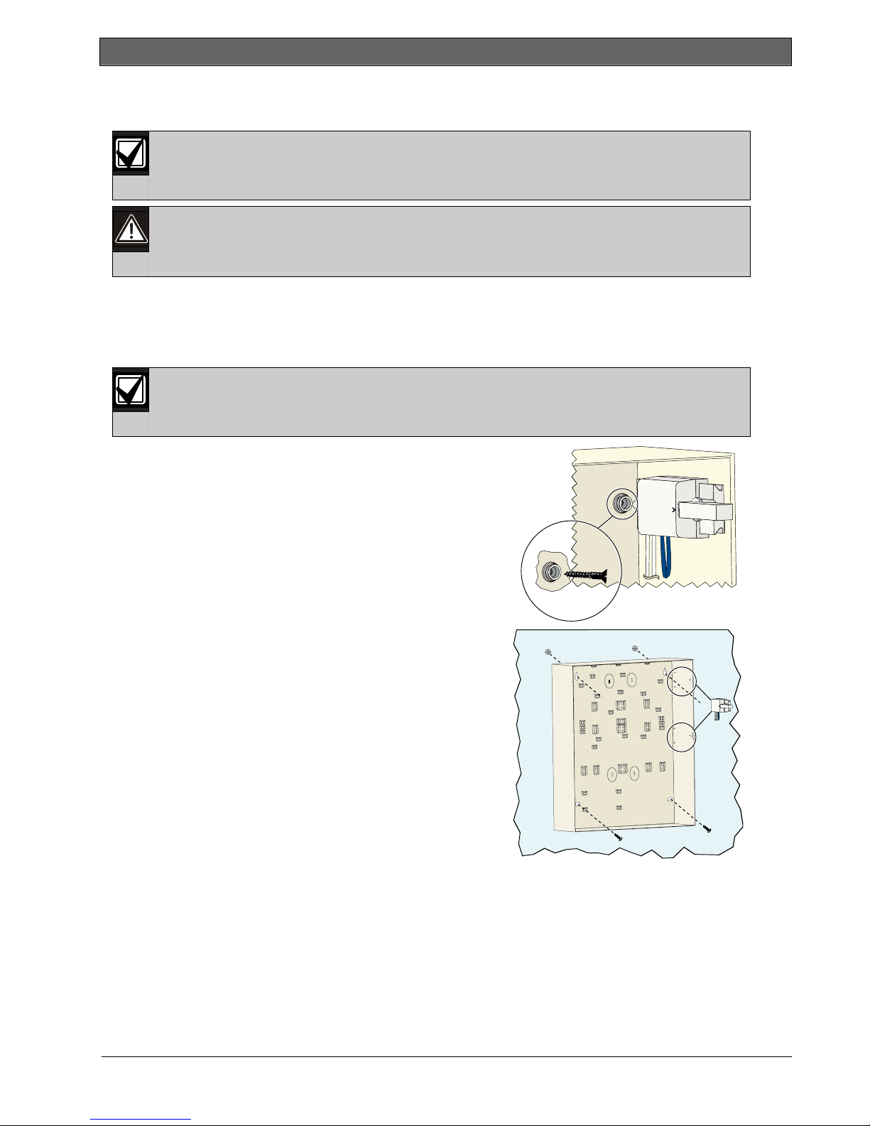
2.1 Enclosure Installation (Step 1)
device must be included into the building installation wiring.
Follow anti-static procedures when handling the control panel board.
Touch the earth ground terminal on the control panel board to discharge any static charge before
working on the control panel board.
Use proper anchor and screw sets when installing the enclosure on non-load-bearing surfaces,
such as drywall.
1. Mount the optional EZTS Tamper Switch.
If a wall tamper is required, insert the round plastic wall plug
before mounting the enclosure.
Refer to the EZTS Cover or Wall Tamper Switch Installation
Guide (P/N: F01U003734) for complete installation
instructions.
Refer to Programming Item 137 on page 39 for enclosure
tamper options.
2. Mount the enclosure. Screws not supplied.
8 Bosch Security Systems, Inc. | 5/07 | F01U025147-01
.
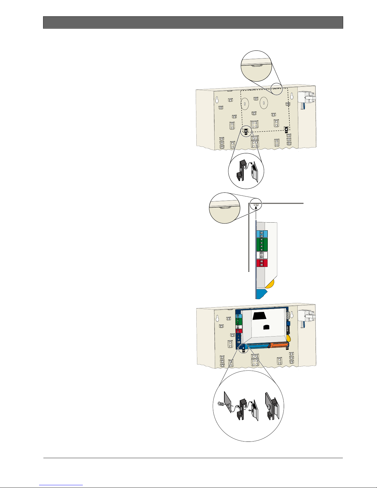
2.2 Control Panel Board Installation (Step 2)
1. Place the mounting clips on the enclosure
standoffs.
Easy Series (ICP-EZM2) | Installer Guide | 2.0 Installation
2. Place the top edge of the control panel board
between the enclosure retaining slots, and then
set the control panel board on the mounting
clips.
3. Secure the control panel board to the mounting
clips using the supplied screws.
=
Bosch Security Systems, Inc. | 5/07 | F01U025147-01 9
Easy Series (ICP-EZM2) | Installer Guide | 2.0 Installation
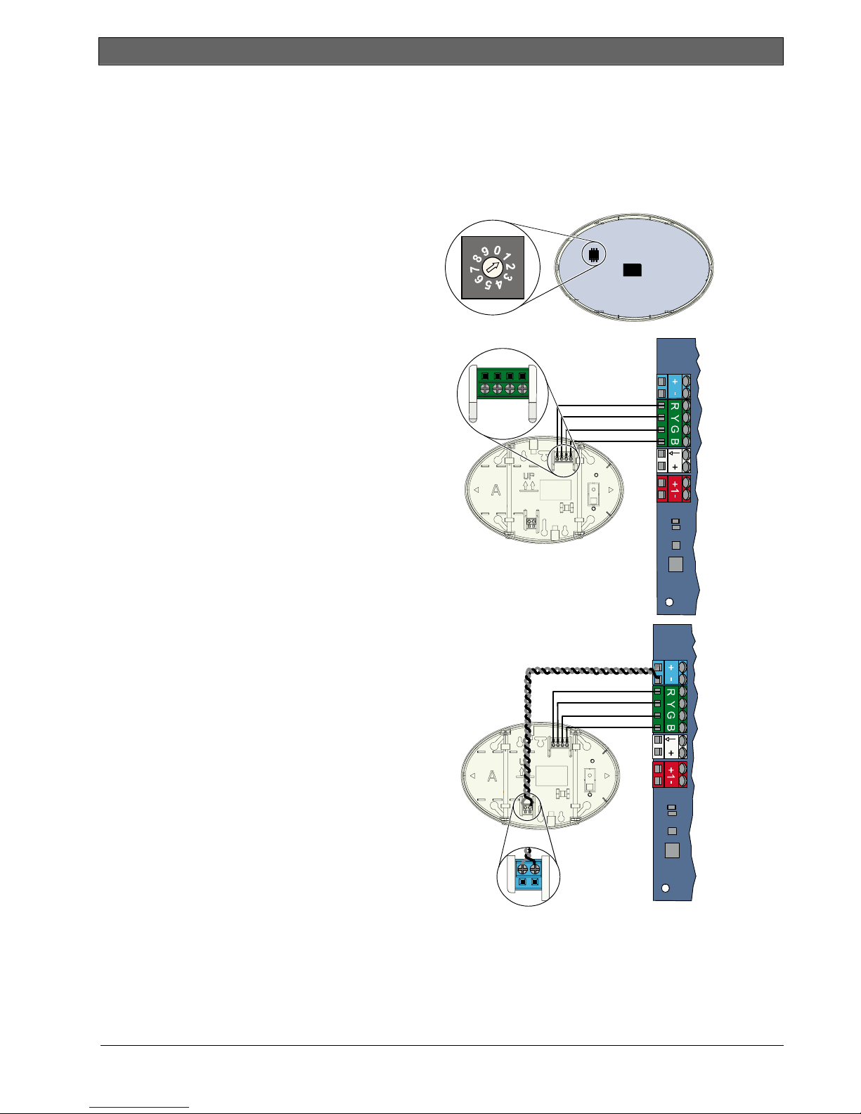
2.3 Control Center Installation (Step 3)
For complete control center installation instructions, refer to the EZ1 Control Center Installation Guide
(P/N: F01U003737) included with the control center.
To ensure proper RF ID reader operation, mount the control center only on a non-metallic surface.
If you install more than one control center, ensure that there is at least 1.2 m (4 ft) of space between each
control center.
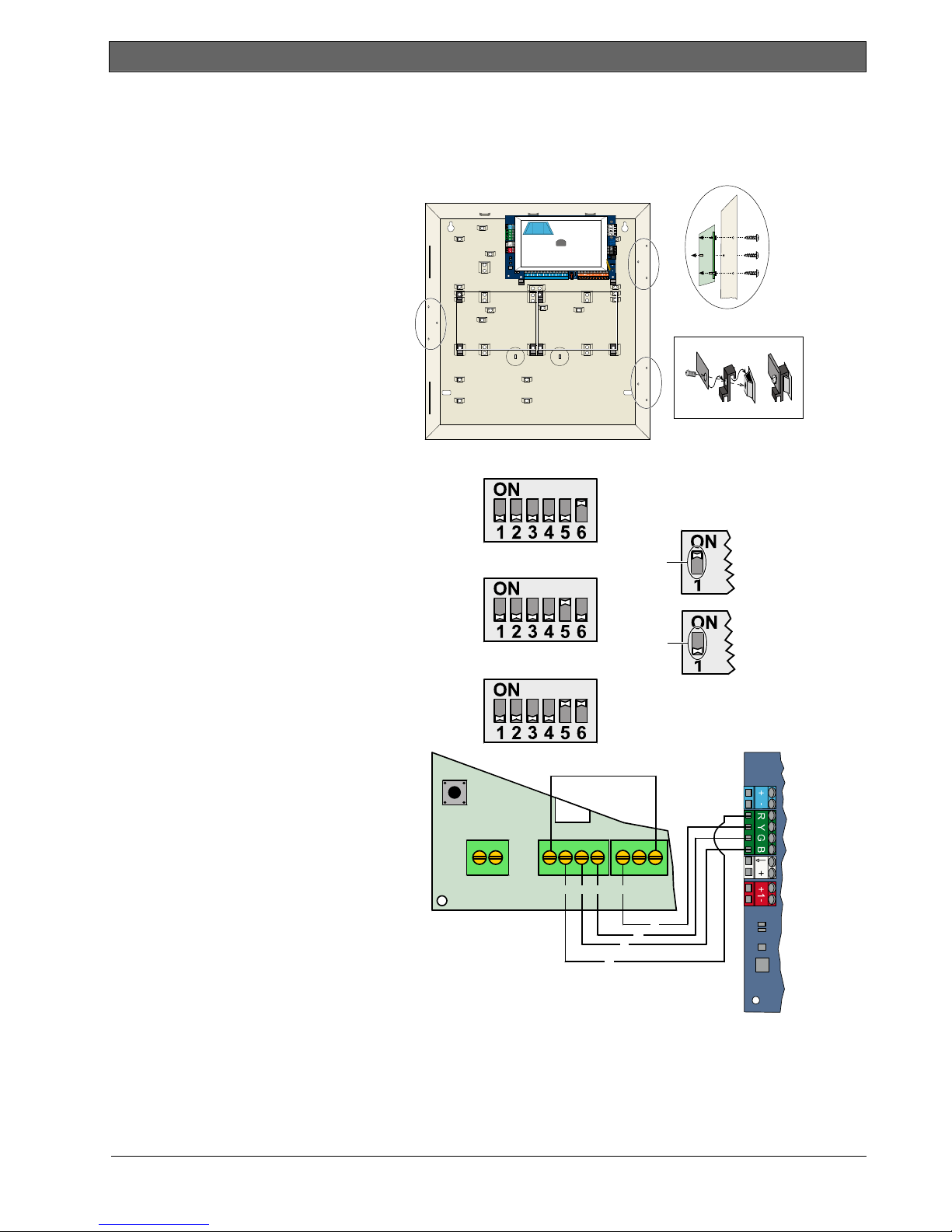
1. Set the address on the control center.
The control panel supports up to four
control centers.
Each control center must have a different
address. Valid addresses are 1 to 4.
The address switch is located on the inside
of the control center.
BGYR
2. Connect the control center data bus
terminals to the control panel data bus
terminals.
3. Connect the control center audio bus
terminals to the control panel audio bus
terminals.
Twisted pair wiring is recommended for
audio bus connections.
If CAT5 cable is used, refer to the following
CAT5 figure.
10 Bosch Security Systems, Inc. | 5/07 | F01U025147-01
-
+
.
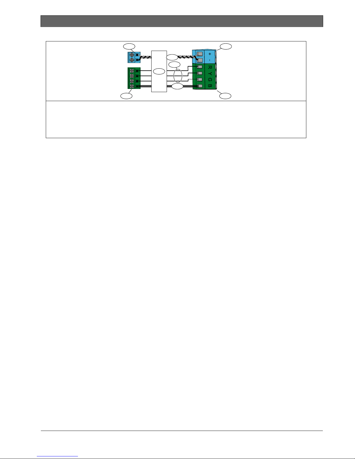
CAT5 Cable Connections
1
+
-
R
Y
G
B
2
1 - Control center audio bus terminals
2 - Control center data bus terminals
3 - CAT5 cable
4 - Blue and blue-and-white-striped
conductors (twisted pair)
Easy Series (ICP-EZM2) | Installer Guide | 2.0 Installation
7
4
5
3
6
8
5 - Solid color conductors
6 - White striped conductors
7 - Control panel board audio bus terminals
8 - Control panel board data bus terminals
Bosch Security Systems, Inc. | 5/07 | F01U025147-01 11
Easy Series (ICP-EZM2) | Installer Guide | 2.0 Installation
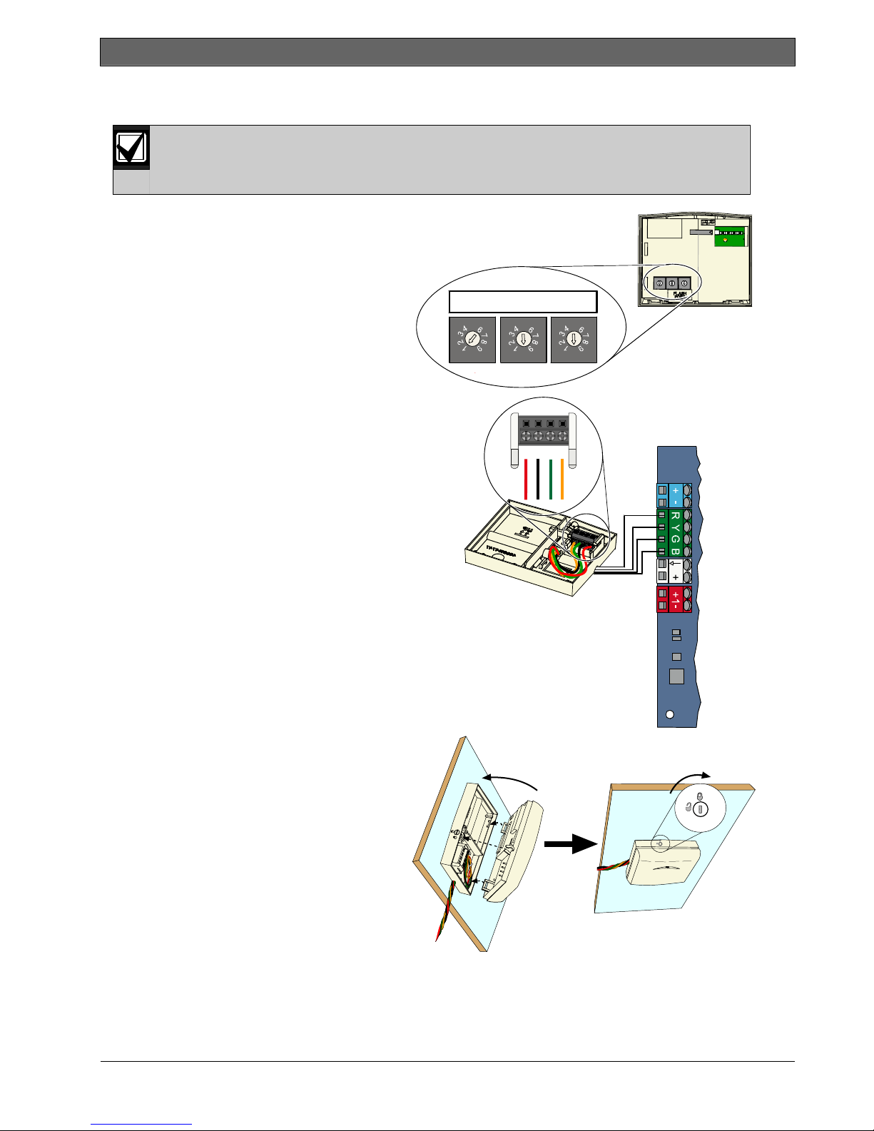
2.4 DX2010 Installation (Step 4)
The control panel supports up to three DX2010 Input Expanders for Points 9 to 32.
Refer to the DX2010 Installation Instructions (P/N: 49533) for more information.
1. Mount the DX2010 into the
control panel’s enclosure, or other
suitable enclosure.
102
=
2. Set the DX2010’s DIP switches.
- Points 9 to 16 = Address 102
- Points 17 to 24 = Address 103
- Points 25 to 32 = Address 104
3. Connect the DX2010 to the
control panel.
Connect a wire jumper to the
TMPR and COM terminals to
disable the DX2010’s tamper
input.
For point wiring options, refer to
Section 2.6 Supervised Point
Connections on page 14.
103
104
+OUT- TMPR 1 COMR B G Y
R
B
ON
OFF
Y
G
12 Bosch Security Systems, Inc. | 5/07 | F01U025147-01
.
2.5 Wireless Hub Installation (Step 5)
Before installing the wireless hub or any wireless devices, refer to Section 3.0 Point Expansion on
page 23, the ISW-BHB1-WX Installation Instructions (P/N: F01U500915), the wLSN Reference
Guide (P/N: F01U009440), and the installation instructions supplied with each wireless device.
1. Perform a site test as described in the
wLSN Reference Guide.
2. Set the S1 switch on the wireless hub to
Address 50 (Position 1).
The control panel supports one wireless
hub.
Switches S2 and S3 are not used for device
addressing.
Easy Series (ICP-EZM2) | Installer Guide | 2.0 Installation
S1
5
0
S2 S3
5
0
5
0
RBGY
3. Connect the hub to the control panel.
4. Put the cover on the wireless hub and lock
the cover to the hub.
5. Install the wireless device bases as
described in their installation instructions.
Bosch Security Systems, Inc. | 5/07 | F01U025147-01 13

Easy Series (ICP-EZM2) | Installer Guide | 2.0 Installation
2.6 Supervised Point Connections (Step 6)
Separate primary AC power and standby battery wires from all power-limited wiring. Refer to
Section 7.2 Power-limited Wire Routing on page 58 for more information.
2.6.1 Fire Point Wiring
Supervised Point 1 supports two- and four-wire smoke detectors.
Supervised Points 2 to 32 support only four-wire smoke detectors.
To program supervised points as fire points, refer to Section 4.2.1 Points on page 31.
For intrusion point configuration, refer to Section 2.6.2 Intrusion Point Wiring on page 15.
1
2
1 2
2
4
Two-wire smoke detector wiring
1 - Power-in terminal
2 - Power-out terminal
3 - Common (negative) terminal
Ω
4 - 2.2 k
end-of-line resistor (P/N: 25899)
3
1
33
5
3
5
7
8
Four-wire smoke detector wiring
1 - Supervised Points 1 to 32
(Point 8 shown in figure)
2 - Programmable Output (PO)
(PO 2 shown in figure)
4
4
3 - Power-in terminal
4 - Power-out terminal
5 - Alarm terminals
6 - Common (negative) terminal
7 - End-of-line resistor (P/N: 25899)
8 - Bosch EOL200 End-of-Line Module
Refer to the Easy Series Smoke Detector Compatibility List (P/N: F01U004853) for compatible two-wire smoke
detectors.
6
6
When using an output to supply power to a four-wire smoke detector, program the output function
for System Reset. Refer to Section 4.2.3 Outputs on page 33.
14 Bosch Security Systems, Inc. | 5/07 | F01U025147-01
Easy Series (ICP-EZM2) | Installer Guide | 2.0 Installation
.
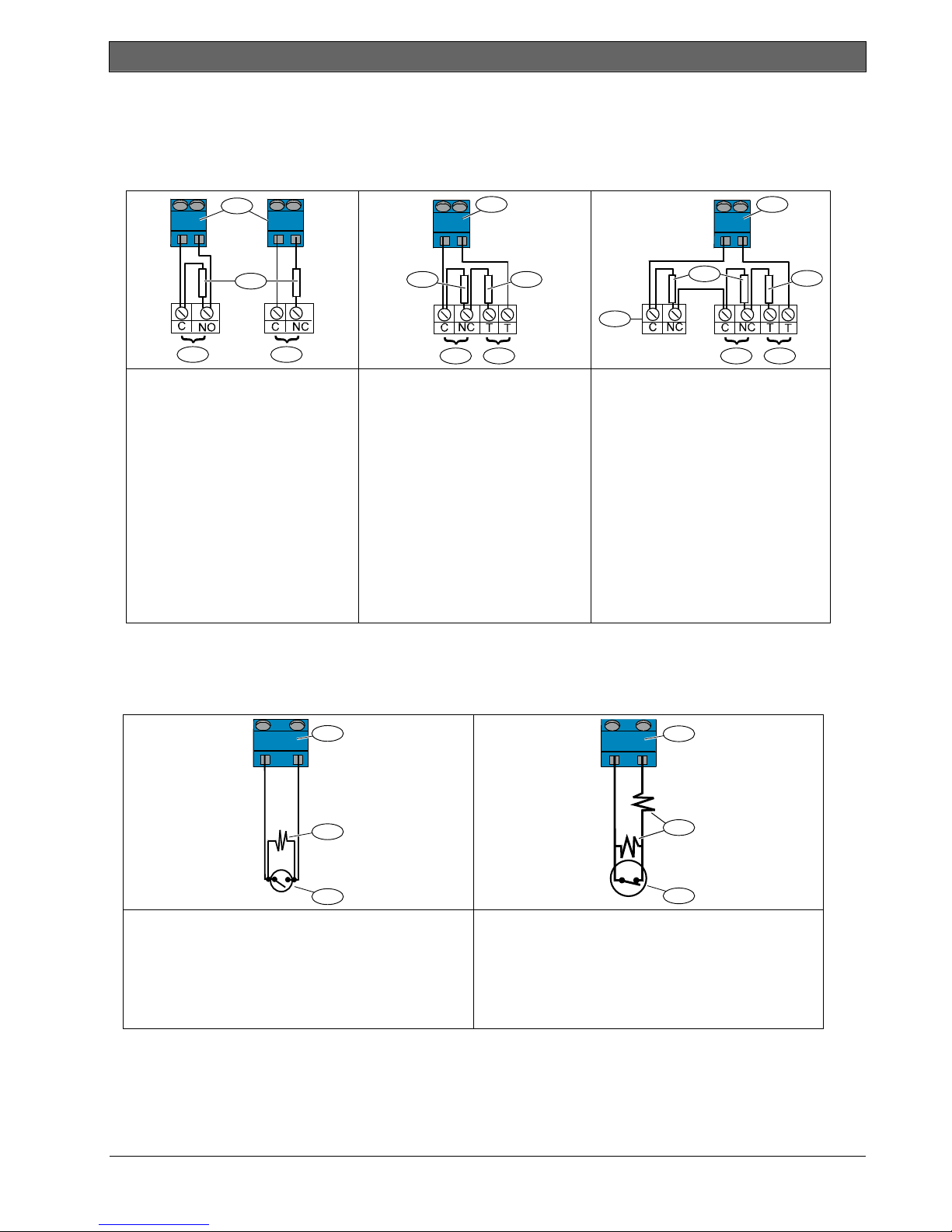
2.6.2 Intrusion Point Wiring
Refer to the figures below to wire Supervised Points 1 to 32 as wired or wireless intrusion points.
To program Supervised Points 1 to 32 as intrusion points, refer to Section 4.2.1 Points on page 31.
For fire point configuration, refer to Section 2.6.1 Fire Point Wiring on page 14.
1
1
1
2
3
Single 2.2 kΩ EOL resistor
1 - Supervised point
(on-board, DX2010, or
wireless input)
Ω
2 - 2.2 k
EOL resistor
3 - Alarm terminals
(Normally Open)
4 - Alarm terminals
(Normally Closed)
45
6
4
Dual 2.2 k
(Point Tamper*)
1 - Supervised point
(on-board, DX2010, or
wireless input)
2 - Alarm terminals
(Normally Closed)
3 - Tamper terminals
(Normally Closed)
4 - 2.2 k
5 - 2.2 k
* This option is not allowed by UL.
2 3
Ω
Resistors
Ω
EOL resistor
Ω
alarm resistor
Dual 2.2 k
(Point Tamper*)
1 - Supervised point (on-board,
DX2010, or wireless input)
2 - Alarm terminals
(Normally Closed)
3 - Tamper terminals
(Normally Closed)
4 - 2.2 k
5 - 2.2 k
6 - Additional devices
(up to 4 maximum)
* This option is not allowed by UL.
5
2 3
Ω
Resistors
Ω
end-of-line resistor
Ω
alarm resistor
2.6.3 Keyswitch Wiring
Refer to the figure below to wire Supervised Points 1 to 32 as keyswitch points (Point 2 shown in figures).
To program Supervised Points 1 to 32 as keyswitch points, refer to Section 4.2.1 Points on page 31.
1
1
4
Single 2.2 kΩ end-of-line resistor option
1 - Supervised point
(on-board, DX2010, or wireless device)
2 - 2.2 k
Ω
resistor
3 - Normally-open momentary or maintained
keyswitch
Bosch Security Systems, Inc. | 5/07 | F01U025147-01 15
2
3
Ω
Dual 2.2 k
resistors (point tamper option)
2
3
1 - Supervised point
(on-board, DX2010, or wireless device)
2 - 2.2 k
Ω
resistor
3 - Normally-closed momentary or
maintained keyswitch
Easy Series (ICP-EZM2) | Installer Guide | 2.0 Installation
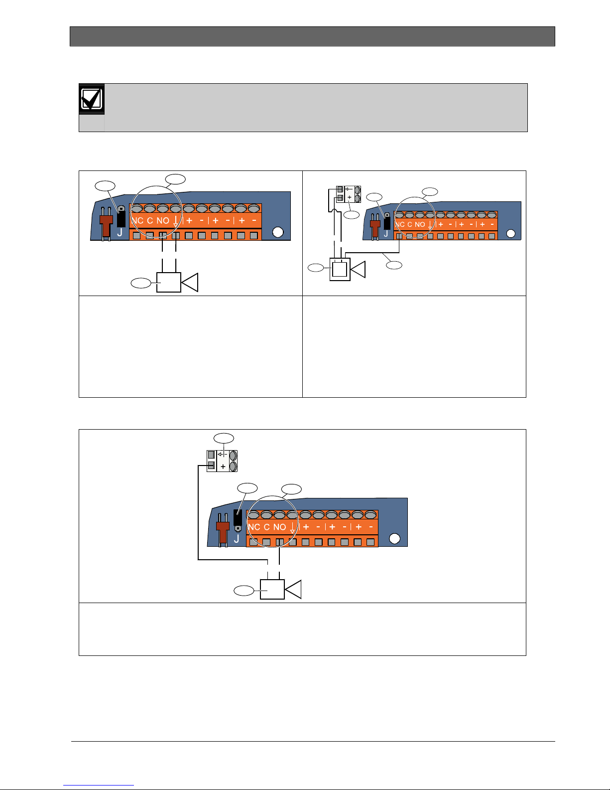
2.7 Programmable Output Connections (Step 7)
Separate primary AC power and standby battery wires from all power-limited wiring. Refer to
Section 7.2 Power-limited Wire Routing on page 58 for more information.
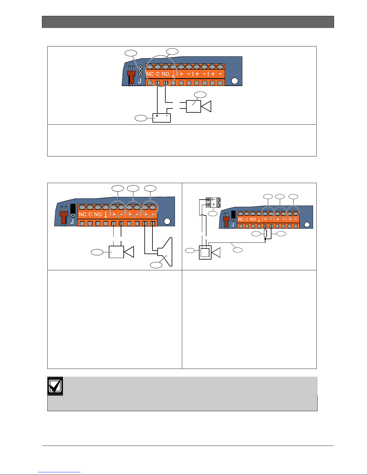
2.7.1 Programmable Output 1 Wiring
Switched 12 V Option
2
1
(+)
(+) (-)
+
4
3
Warning device (without battery)
1 - Programmable Output 1 (PO 1)
2 - Jumper plug position for switched 12 V option
3 - Warning device
Warning device (with battery)
1 - Programmable Output 1 (PO 1)
2 - Jumper plug position for switched 12 V option
3 - Control panel board white auxiliary power
terminals (12 VDC)
4 - Warning device
5 - Warning device activates when trigger voltage
Switched Ground Position
3
is removed
2
3
(-)
-
5
1
1 - Programmable Output 1 (PO 1)
2 - Jumper plug position for switched ground option
3 - Control panel board white auxiliary power terminals (12 VDC)
4 - Warning device
16 Bosch Security Systems, Inc. | 5/07 | F01U025147-01
2
1
(-)(+)
4
.
Dry Contact Option
2
1
(+)
(-)
4
1 - Programmable Output 1 (PO 1)
2 - Jumper plug position for dry contact option (no jumper)
3 - Warning device (normally-open option)
4 - Power source
2.7.2 Programmable Outputs 2 to 4 Wiring
32 4
Easy Series (ICP-EZM2) | Installer Guide | 2.0 Installation
3
21 3
(-)(+)
1
Warning device (without battery)
1 - Warning device (PO 2, 3, or 4)
2 - Programmable Output 2 (PO 2)
3 - Programmable Output 3 (PO 3)
4 - Programmable Output 4 (PO 4)
Ω
5 - 8
speaker (PO 4 option only)
If you program PO 4 as a supervised speaker driver, connect an 8 Ω speaker to prevent speaker
supervision troubles. Refer to Expert Programming Item Number 642 on page 51 for more
information.
For a UL-approved installation, only connect a UL listed, 85 dB sounding device to PO 4.
4
(+)
(-)
5
-
+
5
6
7 8
Warning device (with battery)
1 - Programmable Output 2 (PO 2)
2 - Programmable Output 3 (PO 3)
3 - Programmable Output 4 (PO 4)
4 - Control panel board white auxiliary power
terminals (12 VDC)
5 - Warning device (PO 2, 3, or 4)
6 - Trigger voltage
7 - 10 k
Ω
resistor
(Refer to warning device instructions for
recommended resistor value)
8 - Warning device activates when the
programmable output activates
Bosch Security Systems, Inc. | 5/07 | F01U025147-01 17
Easy Series (ICP-EZM2) | Installer Guide | 2.0 Installation
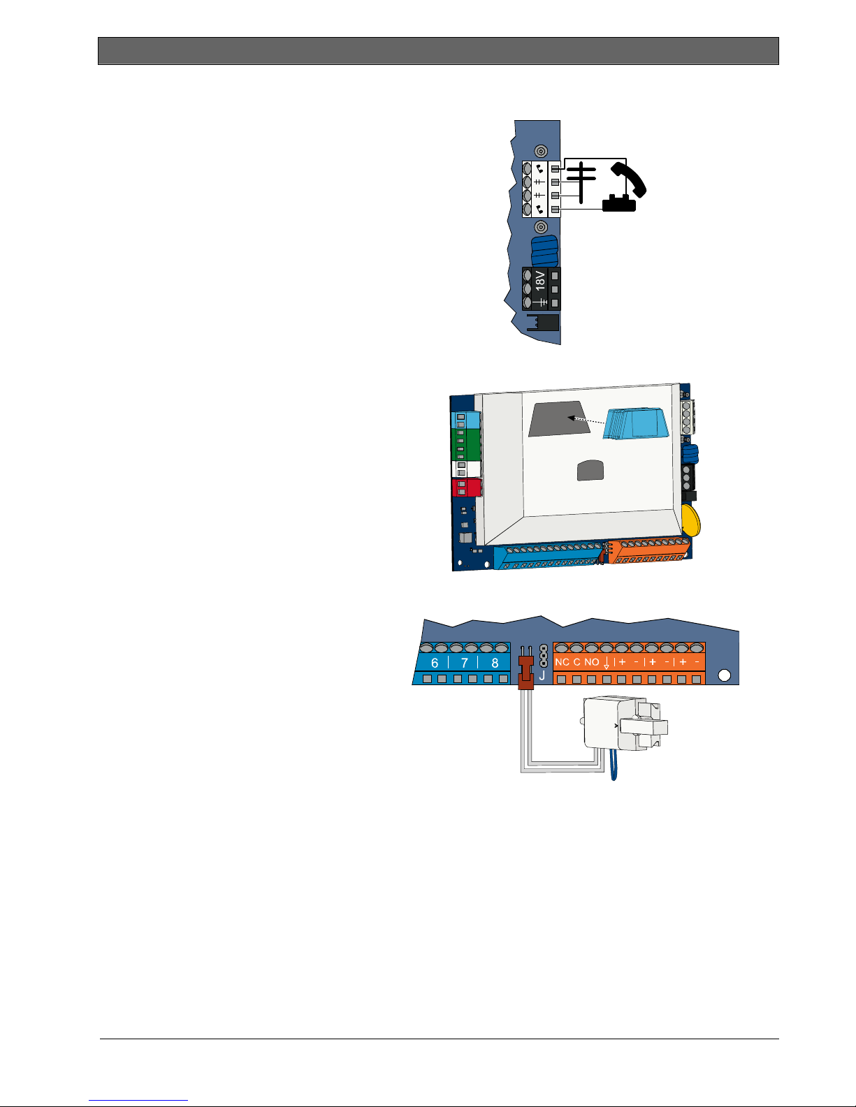
2.8 Phone Line Connections (Step 8)
Connect the incoming phone line and the house
phone to the control panel board.
2.9 Insert Voice Module (Step 9)
The voice module is required for system
operation.
2.10 EZTS Connections (Step 10)
If the optional EZTS Tamper Switch was
installed in Step 1 on page 8, connect its cable to
the two-pin connector on the control panel.
18 Bosch Security Systems, Inc. | 5/07 | F01U025147-01
.
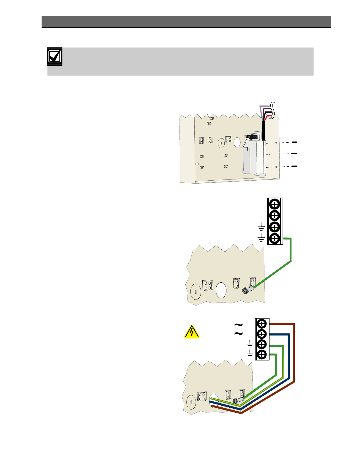
2.11 Power Supply Installation (Step 11)
This system uses either the EZPS wire-in power supply, OR a plug-in power supply. Both power
supplies require the enclosure ground wire and a standby battery.
The EZPS is not investigated by UL.
2.11.1 EZPS Wire-in Power Supply
1. Mount the EZPS on the enclosure using
2. Connect the earth ground wire from the
Follow the instructions below for the power supply used in your installation.
the screws supplied with the EZPS.
EZPS to the enclosure stud.
Easy Series (ICP-EZM2) | Installer Guide | 2.0 Installation
EZPS
L
3. Connect AC power to the EZPS.
100-240 V
0.5 A MAX
47-62 Hz
N
EZPS
L
N
Bosch Security Systems, Inc. | 5/07 | F01U025147-01 19
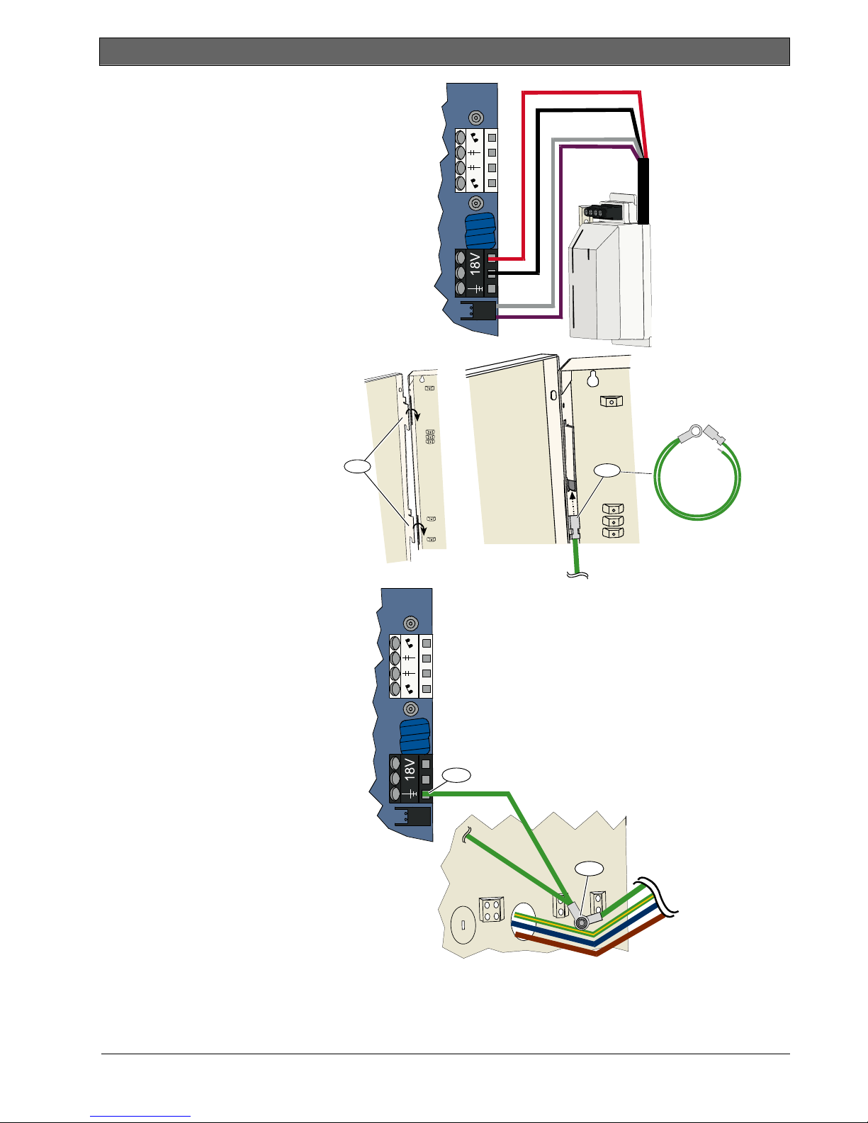
Easy Series (ICP-EZM2) | Installer Guide | 2.0 Installation
4. Connect the EZPS wires to the
control panel board.
5. Insert the door hinges onto the
enclosure.
6. Push the enclosure ground wire
connector onto the unpainted
part of the door’s top hinge.
7. Connect the enclosure ground
wire to the threaded enclosure
stud.
8. Connect the enclosure ground
wire to the control panel
board’s earth ground terminal.
5
8
6
7
EZPS
20 Bosch Security Systems, Inc. | 5/07 | F01U025147-01
.
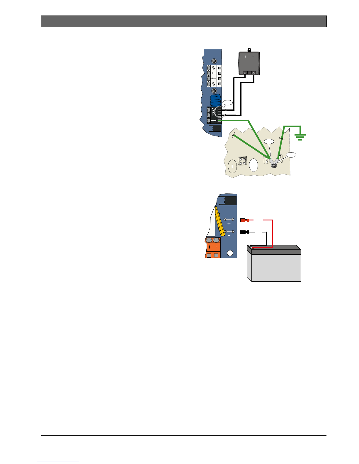
2.11.2 Plug-in Power Supply
1. Connect a ground wire from the enclosure to a good
earth ground source.
2. Connect the enclosure ground wire.
For instructions, refer to Steps 5 to 8 in Section 2.11.1
EZPS Wire-in Power Supply on page 19.
3. Connect the plug-in power supply to the control panel
board.
2.11.3 12 VDC Standby Battery
When all system wiring is complete, apply AC and standby
battery power to the control panel.
Easy Series (ICP-EZM2) | Installer Guide | 2.0 Installation
3
2
1
(+)
(-)
12 VDC
Bosch Security Systems, Inc. | 5/07 | F01U025147-01 21
Easy Series (ICP-EZM2) | Installer Guide | 2.0 Installation
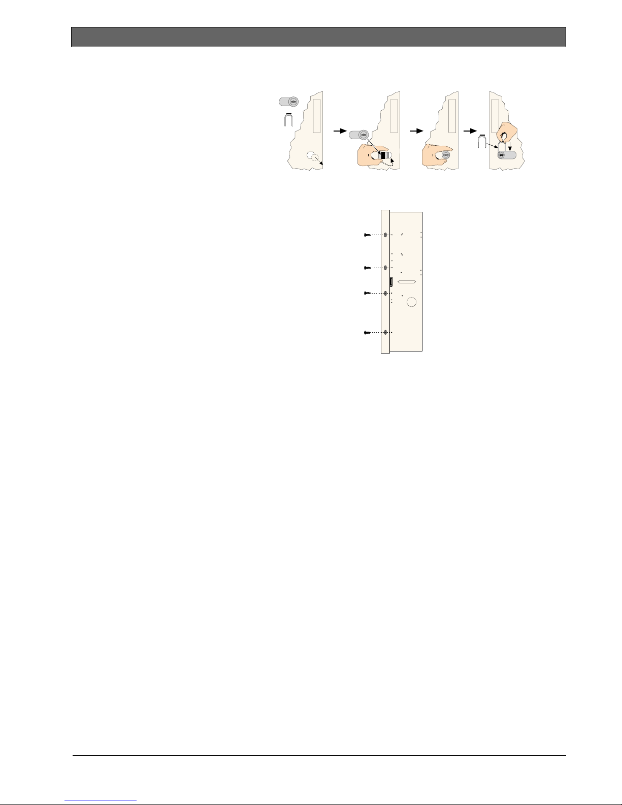
2.12 Secure the Enclosure (Step 12)
To secure the enclosure door:
• Install the enclosure door lock, or
• Secure the door with screws.
Screws not supplied.
OR
2.13 Program the Control Panel (Step 13)
When installation is complete, you can program the control panel.
Refer to Section 4.0 Programming on page 29 for more information.
2.14 Test the System (Step 14)
When programming is complete, you must test the system for proper operation.
Refer to Section 5.0 System Test on page 56 for more information.
22 Bosch Security Systems, Inc. | 5/07 | F01U025147-01
Easy Series (ICP-EZM2) | Installer Guide | 3.0 Point Expansion
.
3.0 Point Expansion
For complete wireless installation and configuration information, refer to the wLSN Reference Guide
(P/N: F01U009440) supplied with the wireless hub, and the installation instructions supplied with each wireless
device.
Wireless support is not investigated by UL.
3.1 Establishing the Wireless Network and Configuring Wireless Devices
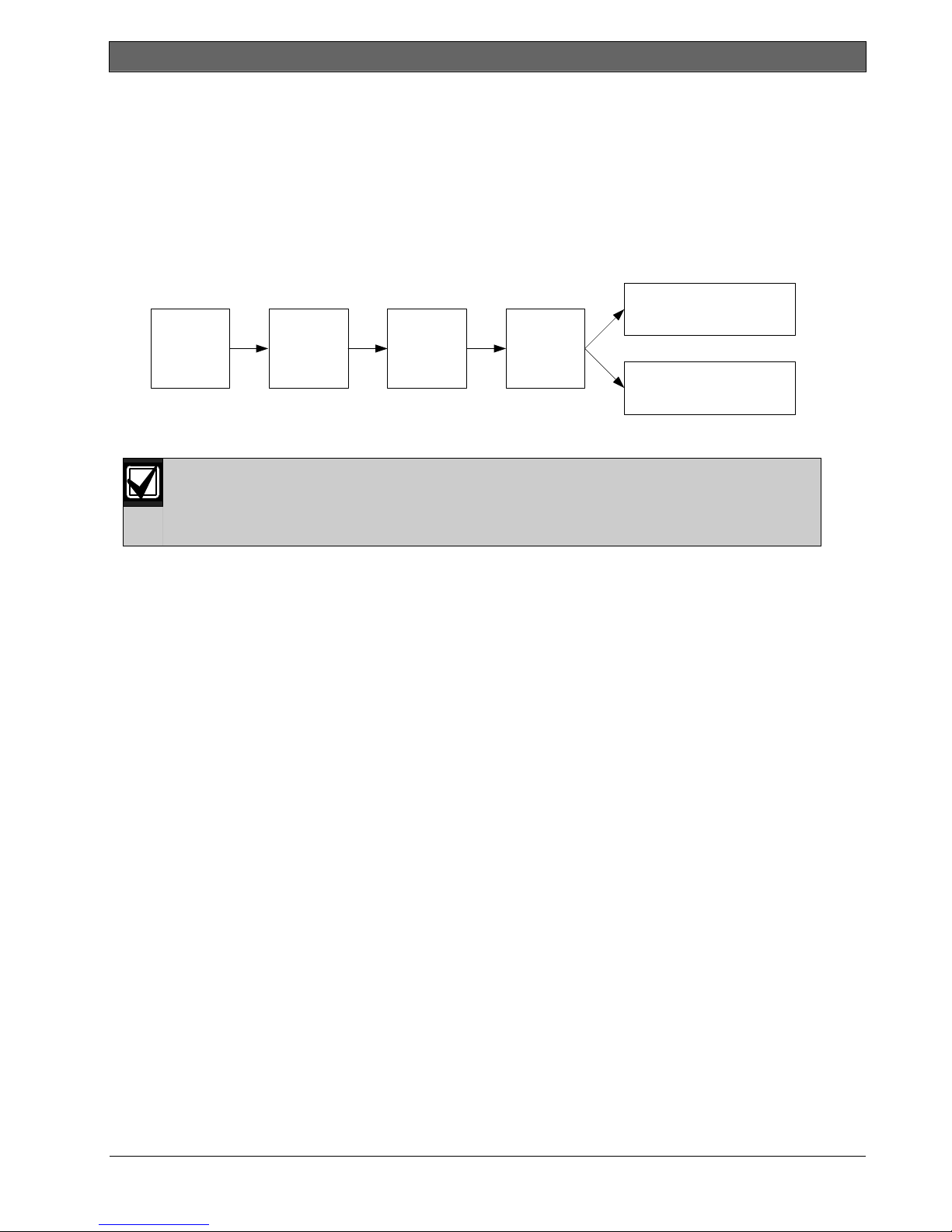
In order for the wireless network to operate properly, the following process must occur as shown below.
Inputs and Outputs
(Point Test)
Discover
Devices
3.1.1 Discover New System
Discovery is the process through which the wireless hub identifies and includes new (undiscovered)
devices into the system.
You can only perform the new system discovery process once. To update an existing wireless
system, refer to Section 3.2 Wireless Maintenance on page 26.
There are three ways to start the discovery process on a new system:
• System Test Button:
1. Ensure that all devices have exited RFSS Mode.
2. Press and hold the System Test button for one second.
The device discovery process automatically starts at the beginning of the Point Test.
• Wireless Configuration Menu:
1. Start a phone session.
Refer to Section 1.3 System Setup on page 5 for phone session options.
2. From the Installer Menu, select System Maintenance, and then select Wireless Configuration.
The device discovery process automatically starts.
• Point Test:
1. Start a phone session.
Refer to Section 1.3 System Setup on page 5 for phone session options.
2. From the Installer Menu:
- Press [1] to select System Maintenance, and then press [2] to select Full System Test.
The discovery process starts at the beginning of the Point Test.
- Press [1] to select System Maintenance, and then press [3] to select System Test Menu. From the
System Test Menu, press [5] to select Point Test.
The discovery process starts at the beginning of the Point Test.
3.1.2 Establish and Configure the Wireless Network
The wireless hub automatically establishes and configures the wireless network.
The wireless hub evaluates each available radio frequency (RF) for noise, RF signal strength, and other
adjacent wireless systems. The wireless hub then selects the frequency with the lowest amount of noise and
least amount of traffic for network operation.
To configure the wireless network, the wireless hub selects the best channel for broadcasting. Once a channel
is selected, the wireless hub then configures all discovered devices to operate on the selected frequency. This
process takes several minutes.
Establish
Network
Configure
Network
Configure
Devices
Key Fobs
(Add/Change User Menu)
OR
Bosch Security Systems, Inc. | 5/07 | F01U025147-01 23
Easy Series (ICP-EZM2) | Installer Guide | 3.0 Point Expansion
3.1.3 Configure Devices
Input and Output Devices
The ISW-BMC1-S135X Door/Window Contact and the ISW-BIN1-S135X Inertia Detector have a
magnetic switch as an input. If the magnetic switch is not used, remove the magnet from the device
before starting the Point Test.
Once the network is established and configured, the system announces “Test all points.” Test the wireless
devices in this order: input devices, output devices, and relay modules.
Do not exit the Point Test until all intended wireless devices are tested. Otherwise, you must
manually add devices to the system.
If extra wireless devices not intended for installation are within the wireless hub’s range, the hub
might also discover these devices. To exclude any unused devices from the system, press [#] (or [5]
from the control center) to exit the Point Test. The wireless hub returns all unused devices to the
undiscovered state.
As you test each device, complete Section 4.3.5 Point Programming Items on page 46, and Section 4.3.6 Output
Programming Items on page 51.
When you restore the device, the system announces the assigned device number.
3.1.4 Test Devices
Point numbers are assigned to wireless devices in the order that the devices are tested (tampered
or faulted and restored). If specific point numbers are preferred for wireless devices, ensure that the
wireless devices are tested in the appropriate order. Otherwise, the system assigns the lowest
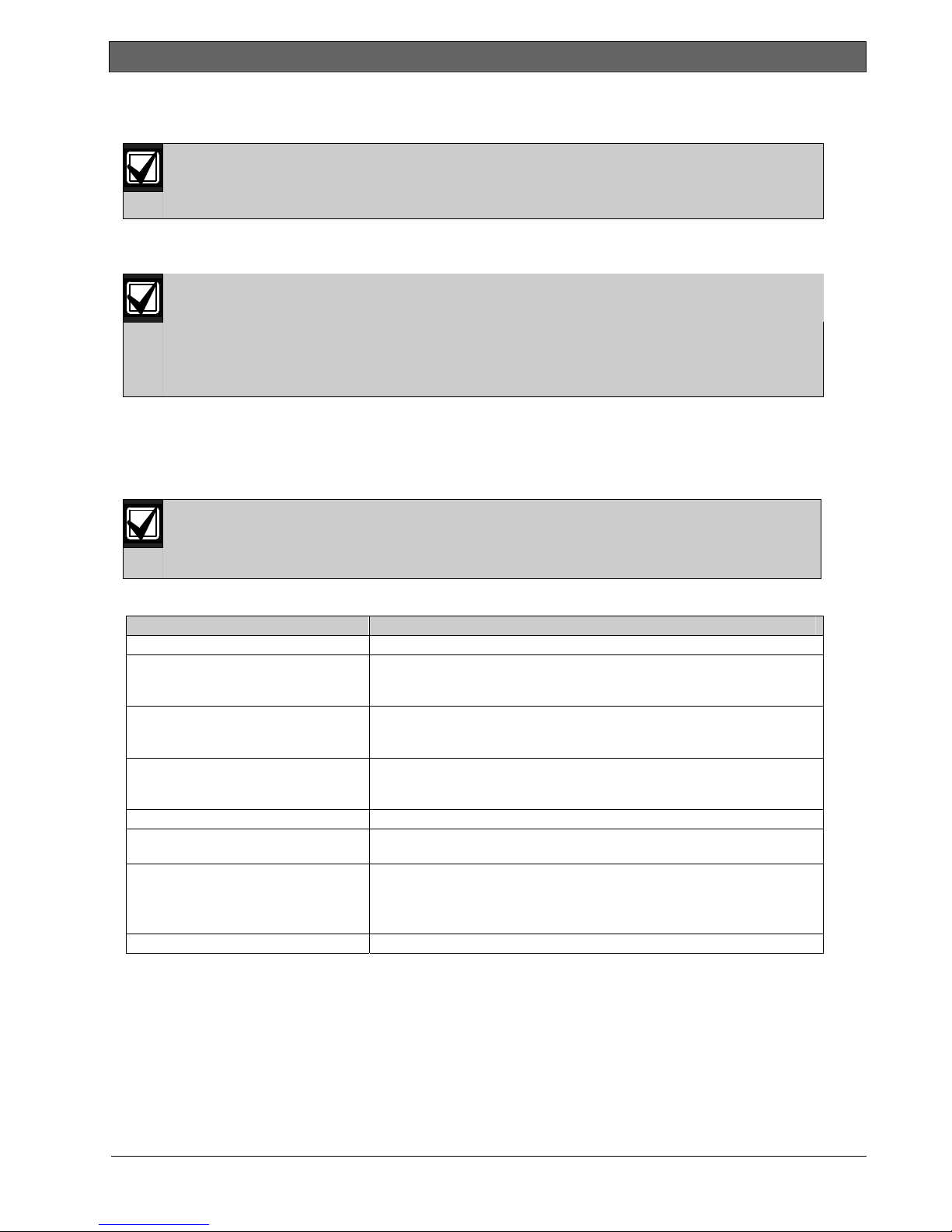
Refer to the following table for instructions on testing each wireless device.
Device To Test:
Motion Detectors Walk across the detector’s coverage pattern.
Smoke Detector
Relay Module
Inertia Detector
Glass Break Detector Cause an alarm and then restore the alarm2, or tamper the detector.3
Mini Door/Window Contact
Recessed Door/Window Contact
Door/Window Contact
Siren Tamper the device.
1
To test the inertia detector, create a shock to cause an inertia alarm, and then restore alarm.
2
To test the glass break detector, use a special tool to cause a glass break alarm, and then restore the alarm.
3
If you tamper the detector, the control panel enrolls the detector, but does not test it. You must create the
available point number to the first tested wireless device.
• Press and release the detector’s test button, or
• Blow smoke into the detector’s chamber to cause an alarm. Restore the
alarm.
• Input: Fault and restore the supervised loop.
• Output: Tamper the device.
Perform both tests only if both the input and output are used.
• Magnetic Switch: Open and then close the switch.
• Inertia Only: Cause an alarm and then restore the alarm
detector.
Open and then close the magnetic switch.
• Open and then close the magnetic switch, or
• Fault and then restore the supervised loop.
Perform both tests only if both the magnetic switch and supervised loop are
used.
3
1
, or tamper the
appropriate alarm and restore the alarm to test the detector.
24 Bosch Security Systems, Inc. | 5/07 | F01U025147-01
 Loading...