

Bosch ICP-COM-IF Installation Manual
Description of the ICP-COM-IF Module
The ICP-COM-
IF Module allows an isolated connection to be created between the MAP5000 (Interface
Module DE) and an external communicator (for e xa mple the AT 2000) via the parallel S1 interface. The
ICP-COM-IF Module offers:
Notes for installation
- The ICP-COM-I F Module can be mounted on the hinged mounting plate or the mounting rails of the
MAP contr ol panel housing.
- A clearance of 15 mm is required on either side for subsequent wiring. Pull to disconnect the
connectors.
- The enclo sur e of a n e xte rna l tra nsm iss ion unit has to be mo unte d s ide b y sid e to the pane l e nclos ur e
where the I CP-COM-IF mod u le is mounted.
Mounting
1. Hook the ICP-COM-IF Module carrier plate into the existing breadboard of the
hinged mounting
plate or onto the mounting rails.
2. Use the screw provided to secure the carrier plate to the bottom rail.
• Seven outputs :
The output signals from the MAP Interface Module DE
control the ICP-COM-IF Module rela ys that provide is olated
changeover contacts (R1 to R7)
• Two inputs:
The inputs ST and R (for the "Communicator fault" or
"Negative confirmation" signals, for instance) can be
controlled via the following:
- isolated contacts
- C points (isolated via optocouplers)
Technical specifications
Rated voltage +10 to +28 V DC
Rated current
67 mA at 28 V or 180 mA at 10 V
Relay contacts rating 3 A/120 V AC, 3 A/28 V DC
Temperature range
−25 °C to +55 °C
Weight 198 g
Dimensions (L x W x H)
132 mm x 85 mm x 20 mm (5.2 inches x 3.3
inches x 0 .8 inches)
Bosch Sicherheitssysteme GmbH
Robert
-Bosch-Ring 5
85630 Grasbrunn
Germany
www.boschsecurity.com
© Bosch Sicherheitssysteme GmbH, 2014
V
3 2014/11
1
ICP-COM-IF
EN
Installation guide
VdS class C G 111040
EN 50131
-2-6 Grade 3
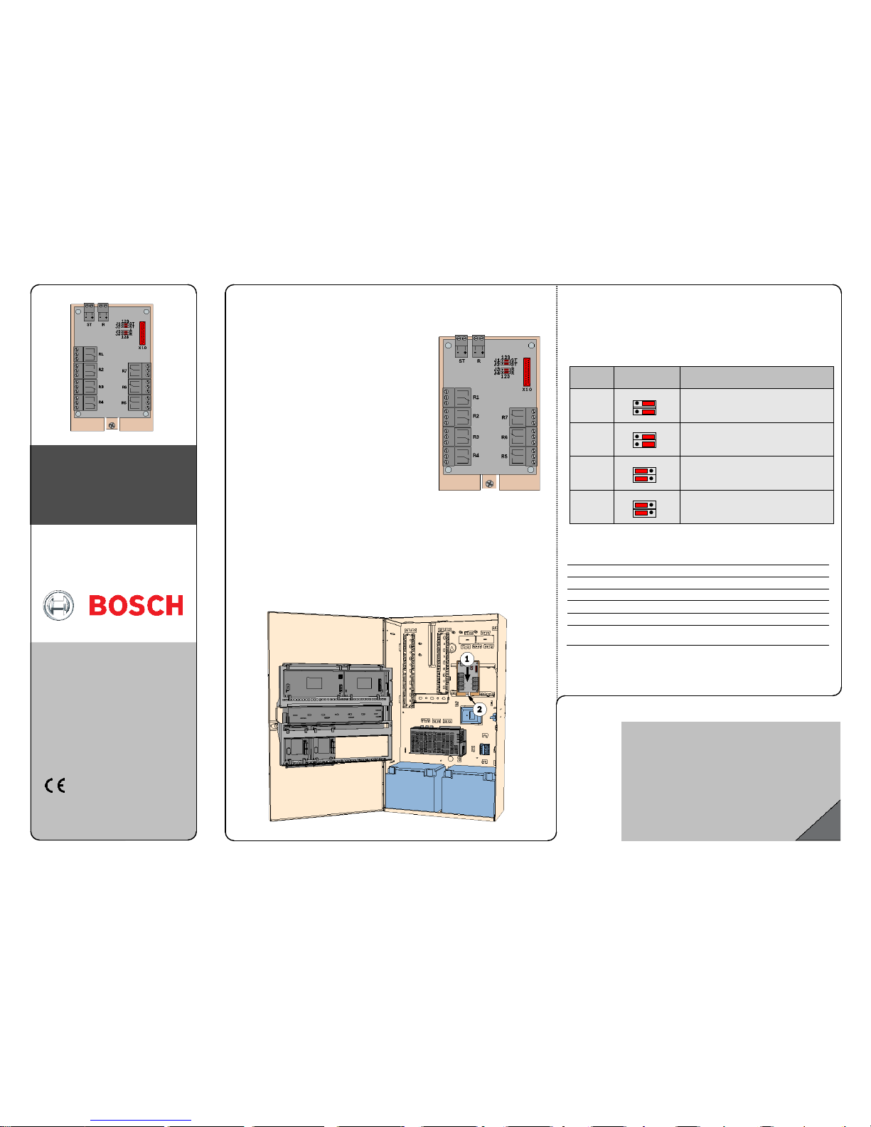
Jumper settings
The inputs ST and R can be controlled via the following:
• isolated contacts
• C points (isolated via optocouplers)
To control the inputs via external "isolated contacts " or "C points", the jumpers mu st be
connected as follows:
Input Jumper setting Description
ST
Control via isolated contact (factory default)
R
Control via isolated contact (factory default)
ST Control via C point
R Control via C point
3
1
J1
ST
2 3 1
J2
ST
2
3
1
J3
R
2
3
1
J4
R
2
1
J1
ST
2
3
1
J2
ST
2 3 1
J3
R
2
3
1
J4
R
2
3
Relays
Output/input
Stand-by mode
Activation with
R1
Output for the communicator alarm line ML1
On
Summary alarm
R2
Output for the communicator alarm line ML2
Off
Duress
R3
Output for the communicator alarm line ML3
Off
Holdup
R4
Output for the communicator alarm line ML4
On
Intrusion/Tamper
R5
Output for the communicator alarm line ML5
On
Summar y Trouble
R6
Output for the communicator alarm line ML6
Off
Fire
R7
Output for the communicator alarm line ML7
Off
Armed (any area)
ST
Input from externa l communicator
Communicator fault
R
Input from externa l communicator
Negative confirmation
© Bosch Sicherheit
ssyste me GmbH, 2014
V
3 2014/11
2
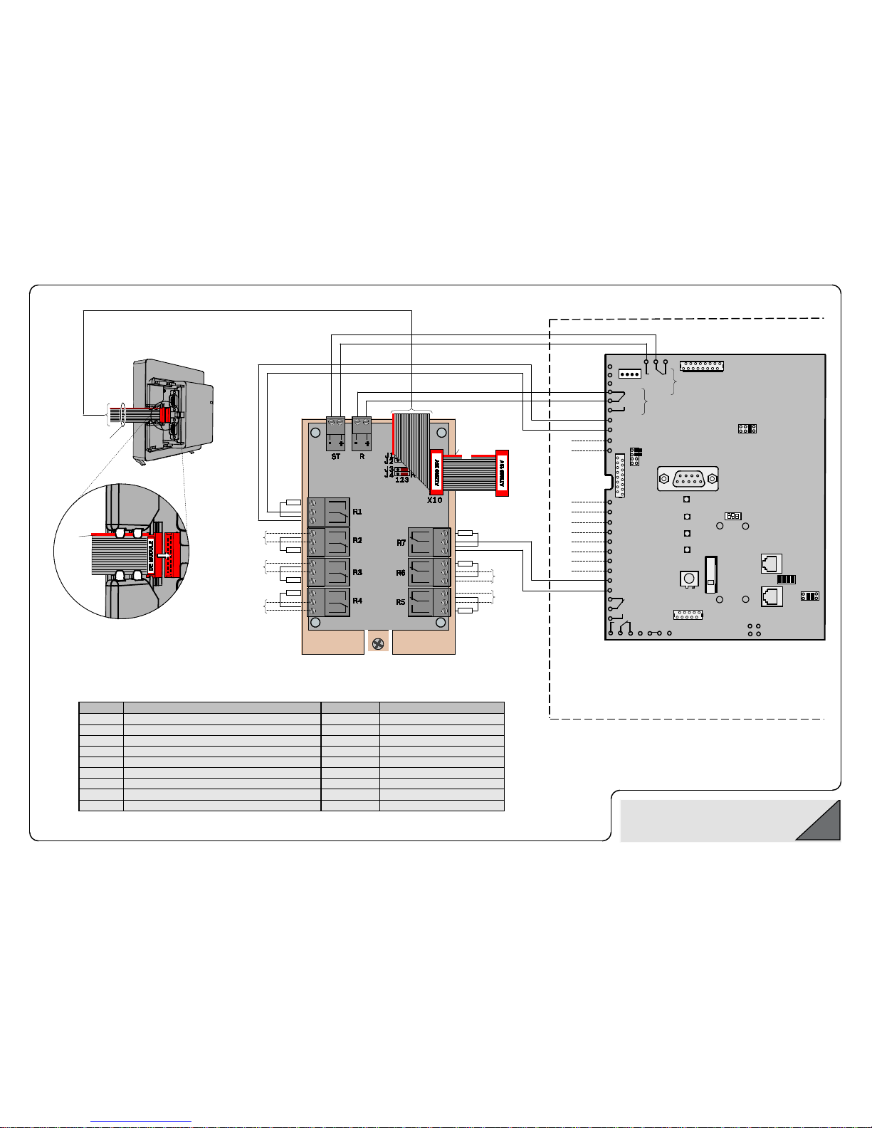
A
B
Relay 1
AT 2000
A
B
A
B
A
B
A
B
A
B
A
B
Relay 2
Remote communicator, for example the AT 2000
R1A
R1B
R1C
C1C
ML7
ML6
ML5
ML4
ML3
ML2
ML1
AT 2000 programming
•
Relay 1: "Contin uous activation", stand-by "on"
•
Relay 2: "5 seconds", stand-by "off"
•
ML1–ML7: Conventional Lines Intrusion
Relay 2:
Negative
confirmation
Relay 1:
Communicator fault
C1B
C1A
ICP
-COM-IF
MAP Interface Module DE
The ribbon cable is
a
ttached to the MAP
Inter
face Module DE
Parallel S1 interface
Red
marking at
top
1.
The size of the terminal resistors (RE) to be looped in
depends on the communicator (for example 10 k for the AT 2000).
2.
Pull to disconnect the connectors.
ML2
ML3
ML4
ML6
ML5
Red
m
arking
at top
 Loading...