

Bosch AMAX panel 4000, AMAX panel 4000 EN, ICP-AMAX4-P1, ICP-AMAX4-P2-EN, ICP-AMAX-P3-EN Installation Manual
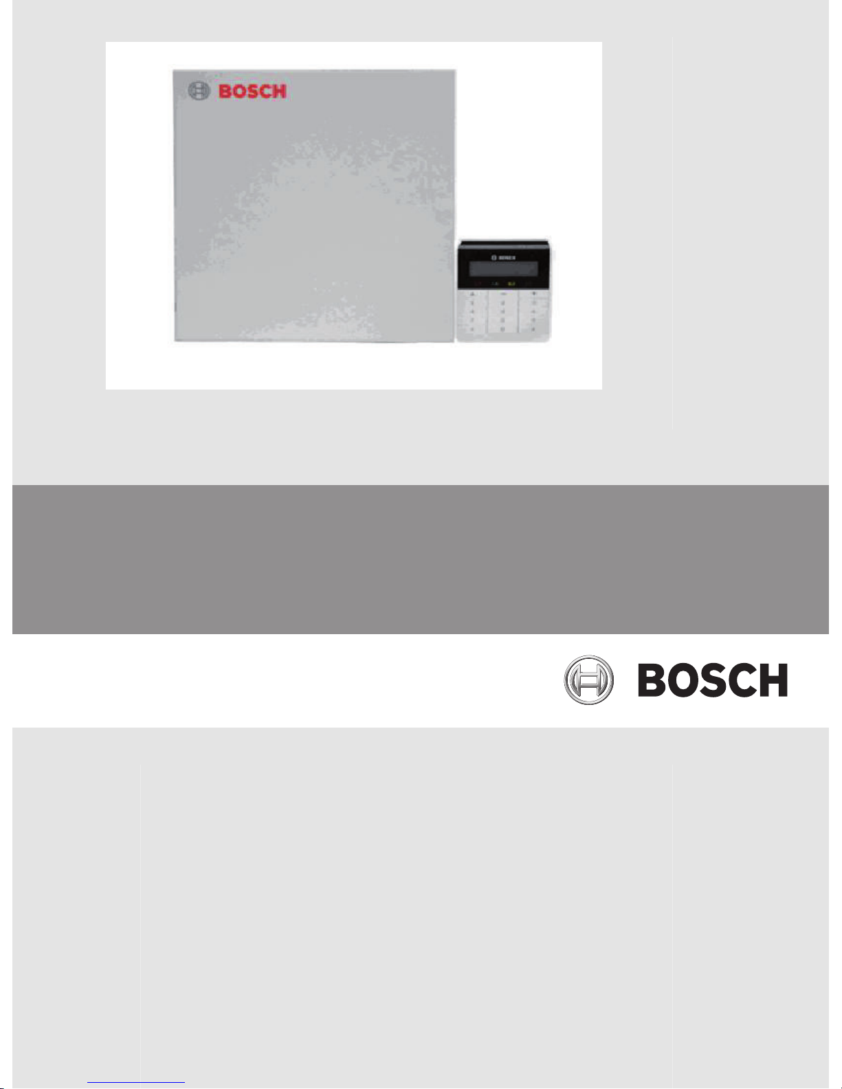
AMAX panel 4000 / AMAX panel 4000 EN
ICP-AMAX4-P1 / ICP-AMAX4-P2-EN / ICP-AMAX-P3-EN
en Installation Guide


Table of contents
1
Graphics 7
2
Safety 8
3
Short Information 9
4
System overview 10
4.1 Communication 10
4.2 Zones 10
4.3 Tamper Description 10
4.4 Area 10
4.5 User 10
4.6 Programmable Output 10
4.7 Key Switch 10
4.8 Event Log 10
4.9 Keypads 10
5
Optional Modules and Peripheral Devices 11
5.1 Keypad 11
5.1.1 Brief Introduction 11
5.1.2 Address Setting 11
5.1.3 Wiring and Installation 12
5.1.4 Test 13
5.2 DX2010 Input Expansion Module 13
5.2.1 Installation 13
5.2.2 Wiring 13
5.2.3 Tamper 15
5.2.4 Address Setting 15
5.2.5 Status Indicator 16
5.2.6 Test 16
5.3 DX3010 Output Expansion Module 17
5.3.1 Installation 17
5.3.2 Wiring 17
5.3.3 Address Setting 18
5.3.4 Test 19
5.4 B426 Network Interface Module 19
5.4.1 Brief Introduction 19
5.4.2 Installation 19
5.4.3 Wiring 19
5.4.4 Address Setting 20
5.4.5 Configuration 20
5.4.6 Status Indicator 20
5.4.7 Test 21
5.5 ITS-DX4020-G Communication Module 21
5.5.1 Brief Introduction 21
5.5.2 Installation 21
5.5.3 Connection 21
5.5.4 Test 22
5.6 RF 3227E RF Receiver 23
5.6.1 Brief Introduction 23
5.6.2 Installation 23
AMAX panel 4000 / AMAX panel 4000
EN
Table of Contents | en 3
Bosch Sicherheitsysteme GmbH Installation Guide 2013.07 | 03 | F.01U.267.112

5.6.3 Address Setting 26
5.6.4 Wiring 26
5.6.5 Status Indicator 27
5.7 RFRC-OPT Radion Receiver 27
5.8 Remote Programming Software 27
5.9 Programming Key / Firmware Upgrade Key 27
6
Installation 28
6.1 Module Installation 28
6.2 Battery Installation 29
6.3 System Power Up 30
6.4 System Status Indicator 31
6.5 Prerequisites for Certification conform Installation 31
6.5.1 EN 50131-3 Grade 2, Environmental Class 2 31
7
Settings 32
7.1 Communication and Reporting 32
7.1.1 Receiver Telephone number /IP Address and Port 32
7.1.2 Receiver Subscriber ID Number 33
7.1.3 Receiver Transmission Format 33
7.1.4 Receiver Network Programming Options 37
7.1.5 Dual IP 38
7.1.6 System Reporting 39
7.1.7 Automatic Test Report 44
7.1.8 Report Expiry Time 44
7.1.9 Remote PC Settings 44
7.1.10 Domestic Call 45
7.2 Zones 46
7.2.1 Zone Inputs 46
7.2.2 Zone Function Settings / Zone Types 47
7.2.3 Zone Function Settings / Zone Options 53
7.2.4 Adding and Changing Zone 57
7.2.5 Zone Indication Keypad and Event Log 57
7.3 Outputs 58
7.3.1 Onboard / Extension Output 58
7.3.2 Output Events 58
7.3.3 Output Options 63
7.3.4 Alarm Siren Ringing Time 64
7.4 Access Codes 64
7.4.1 Installer Code 64
7.4.2 User Codes 64
7.5 System Settings - General 65
7.5.1 Installer Access Until Next Arming 65
7.5.2 Force Arm When System Is In Trouble Condition 65
7.5.3 Siren / PO-1+PO-2 Supervision 65
7.5.4 Keypad 2 Button Alarm 65
7.5.5 Phone Line Monitor 65
7.5.6 Beep For Warning Devices 65
7.5.7 Silence Warning Device When Disarmed 65
7.5.8 Event Record Count per Set/Unset Period 66
7.5.9 System Tamper Indication In Area 66
4 en | Table of Contents
AMAX panel 4000 / AMAX panel 4000
EN
2013.07 | 03 | F.01U.267.112 Installation Guide Bosch Sicherheitsysteme GmbH

7.5.10 Internal Siren Beep As Indication 66
7.5.11 Battery Check Interval 66
7.5.12 Cross Zone Timer 66
7.5.13 AC Power Supply Fault Report Delay 66
7.5.14 Date and Time 66
7.5.15 Fault Inquiry 66
7.5.16 Quick Arming 77
7.5.17 Keypad Settings 77
7.5.18 Fault Report Settings 77
7.5.19 Zone Tamper Bypass when DEOL Zone is Bypassed 78
7.6 System Settings - RF Options 78
7.7 Area Settings 78
7.7.1 Common Area 78
7.7.2 Area Delay 79
7.7.3 Keypad Area 79
8
Configuration 80
8.1 System Power Up 80
8.2 System Status Indicator 80
8.3 Installer and User Code Commands 80
8.4 Reset to Factory Default Settings 82
8.5 Programming with Keypad 82
8.5.1 LCD Keypad Menu Programming 82
8.5.2 LED/LCD Keypad Programming 90
8.6 PC Programming 91
8.6.1 Direct Connection 93
8.6.2 Modem Connection 95
8.6.3 IP Connection 100
8.7 Programming with the ICP-EZPK Programming Key 105
8.8 Firmware Upgrade with the ICP-EZRU2 Upgrade Key 106
9
Programming 107
9.1 Communication and Reports Setting 107
9.2 Zone Programming 113
9.3 Output Programming 124
9.4 Access Codes 129
9.5 System Programming 135
10
Keypad Usage and Operations 153
10.1 Keypad Operating Instructions 153
10.2 Arming and Disarming the System 158
10.2.1 Arming the System 158
10.2.2 Disarming the System 159
10.3 Faults and Tamper Conditions 159
10.3.1 System Fault or Tamper Analysis Mode in LED Keypad 159
10.3.2 System Fault or Tamper Analysis Mode in Text Keypad 161
10.4 System Test 162
10.4.1 Siren Test 162
10.4.2 Communication Test 162
10.4.3 Walk Test Mode 162
10.5 Event Log Recall Mode 162
10.6 Reset the Control Panel 163
AMAX panel 4000 / AMAX panel 4000
EN
Table of Contents | en 5
Bosch Sicherheitsysteme GmbH Installation Guide 2013.07 | 03 | F.01U.267.112

10.7 Bypassing 163
10.7.1 Bypassing Zones 163
10.8 Codes 164
10.8.1 Add/Change and Delete User Code 164
10.8.2 Change Individual Code 165
10.9 Keypad Alarm Operation Commands 165
10.9.1 Keypad Panic Alarm 165
10.9.2 Keypad Fire Alarm 166
10.9.3 Keypad Medical Alarm 166
10.10 Domestic Dialing 166
11
Troubleshooting 167
12
Maintenance 170
13
Technical Data 171
6 en | Table of Contents
AMAX panel 4000 / AMAX panel 4000
EN
2013.07 | 03 | F.01U.267.112 Installation Guide Bosch Sicherheitsysteme GmbH
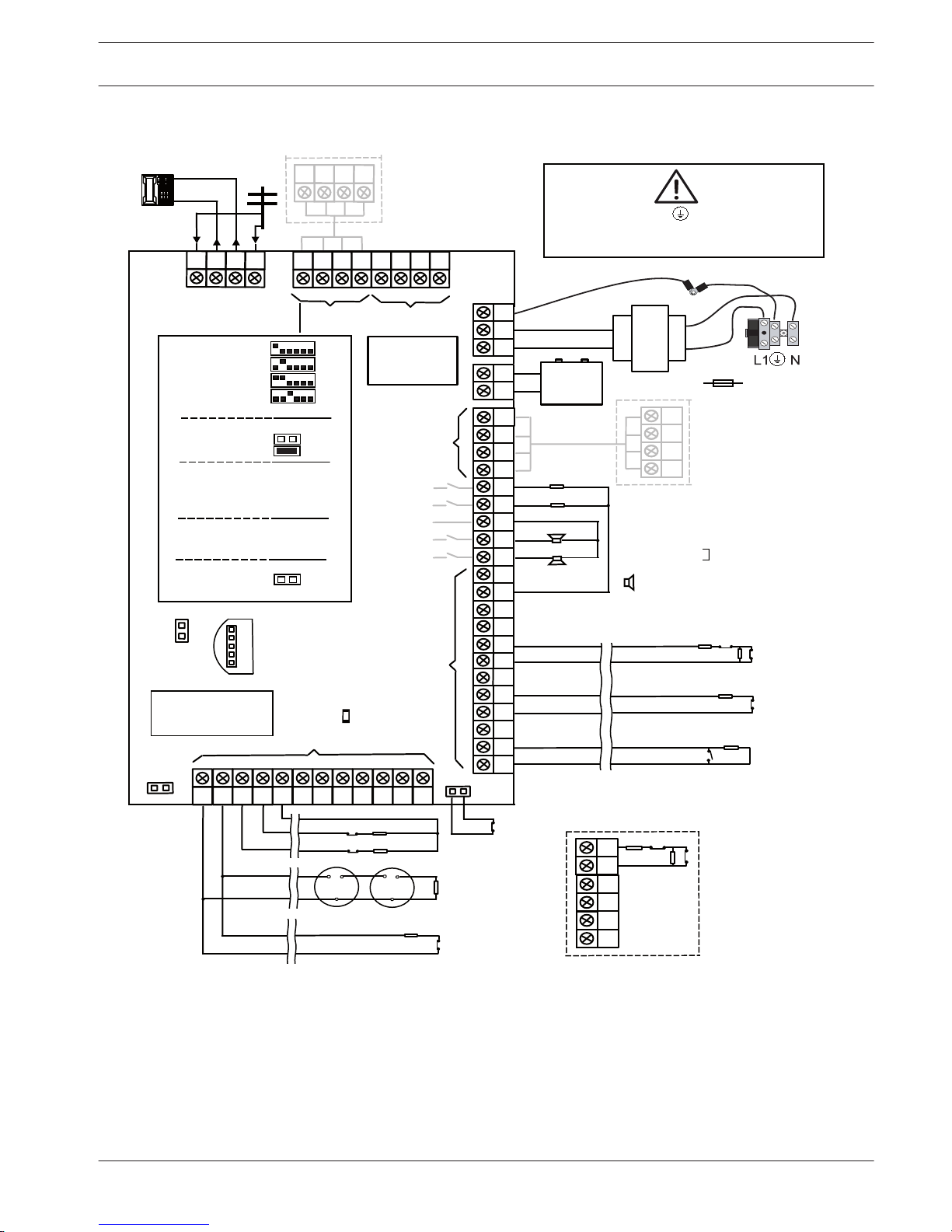
Graphics
Pro
gram Key Port
GND
-
+
A C
A
C
Transformer
Battery
Tam
per
L2 COM
COM
COM
L1a
L3
L4
L5
L6
L7
L8
L9
COM
COM
COM
COM
L10
L11
L12
L13
L14
L15
L16
P0+4
R
B
G
Y
AUX1
-
AUX2
-
AUX1
+12V
Y
G
B
R
RINGRHTHTIP
L1b
P0+3
P0+
P0-2
P0-1
Zones
Bosch Option
Bus 2 < 900mA
+12V
+
0 V
1
2
3
3
1 Tamper Switch
2 Zone Switch
3 EOL 2,2 k
3
2
3
2
Fuse 1 A
PO+4: < 750mA
PO+3: < 750mA
PO -2: < 500mA
PO -1: < 500mA
230V ~50Hz
230mA
Wac
hdog
outpu
t
<100
mA
12V < 18Ah
18VAC@50VA
Zones
AUX 1: < 900mA
AUX 2: < 900mA
AUX Power
Fir
e
Intrusion
Risk of shock if N,L1 or is connected incorrectly.
For operation safety, the ground terminals must
be connected.
3
3
2
Slow flash: Normal state
On: Trouble state
Off: Trouble state
_
_
_
_
_
_
_
_
+12V
+12V
+12V
COM
_
12V 7Ah
AUX2
+12V
_
COM
supervised
PO-5
Z1
2
2
3
3
Keypads:
IUI-AMAX4-TEXT
IUI-AMAX3-LED16
IUI-AMAX3-LED8
Keypads:
IUI-AMAX-LED8
IUI-AMAX-LCD8
I/O Moduls:
DX2010 Adr. 103 - 108
DX3010 Adr. 150 - 151
DX4010 Adr. 253
Communicators:
DX4020G Adr. 134
B426 Adr. 134(6) / 250(9)
RF Receiver:
RF3227E 1=
RFRC-OPT 1= (1)
1 =
2
=
3 =
4
=
1 =
2 =
Bosch Option
Bus
1 < 900
mA
COM
R
B
G
Y
R
B
G
Y
R
B
G
Y
♥
IUI-AMAX3
+4 Keypad
3
1
2
1
Facto
ry
Default
5-16 Inst. Guide
I
2000mA
100 Ω - 2,2 k
_
<
∑
3
Figure 1.1: Wiring Diagram
1
AMAX panel 4000 / AMAX panel 4000
EN
Graphics | en 7
Bosch Sicherheitsysteme GmbH Installation Guide 2013.07 | 03 | F.01U.267.112
Safety
This system / product must be installed by a qualified installer / service person.
During installation and wiring, the control panel power source must be switched-off to prevent
equipment damage.
– To switch off the Power Source, an easy accessible circuit breaker must be available.
– The System / product must be connected to a socket-outlet with a protective earthing
contact
The User has to disconnect all Telecommunication Network Connectors before unplug the
power adaptor.
After the control panel wiring is completed, connect the AC power and backup batteries.
The Mains indicator on the keypad will light to show that AC power is connected.
Notice!
- Use only non spillable battery
- Battery must be recycled
- When battery is not replaced correctly, risk of fire explosion or burning
- Replace the battery every 3-5 years under normal conditions of use.
- Place a Label with change date on the battery
Notice!
The system must be installed and maintained by qualified installer / service person.
Bosch recommends testing the whole alarm system at least once a week.
Maintenance should be done by qualified installer / service person four times a year.
Consequences
Danger!
As static-sensitive components are included in PCBs, anti-static steps should be followed and
they should be carefully installed.
Before installing the alarm control panel, the static electricity possibly carried should be
discharged by contacting the grounding terminal of the alarm control panel.
2
8 en | Safety
AMAX panel 4000 / AMAX panel 4000
EN
2013.07 | 03 | F.01U.267.112 Installation Guide Bosch Sicherheitsysteme GmbH

Short Information
Congratulations on selecting the AMAX panel 4000 for your installation. Spend some time
reading through this guide and familiarize yourself with the outstanding Operation and
installation features of this system so that you can get the most from your unit. In all aspects
of planning, engineering, styling, operation, convenience and adaptability, we try to anticipate
your every possible requirement. Programming simplicity and speed are our major
considerations; we believe that our objectives have been attained. This installation guide
explains all aspects of programming the AMAX panel 4000 from factory default to final
commissioning. All system parameters and options are dealt with in detail, but adaptability
differs with individuals. Each control panel can be tailored to meet your requirements quickly
and easily. The programming simplicity makes your installation quick, accurate and rewarding.
The AMAX panel 4000 equipped with 16 on-board wired zones can be expanded to 64 wired
zones.
3
AMAX panel 4000 / AMAX panel 4000
EN
Short Information | en 9
Bosch Sicherheitsysteme GmbH Installation Guide 2013.07 | 03 | F.01U.267.112
System overview
Communication
The AMAX panel 4000 transmits reports with Contact ID and SIA, also supports domestic call.
With additional modules B426 and/or DX4020G Conettix IP via Ethernet or GPRS is supported
as well as dual IP communication. AMAX panel 4000 supports remote programming and
system control by using remote programming software A-LINK PLUS.
Zones
The alarm control panel supports up to 64 zones, including 16 on-board zones and up to 48
zones increased with upto six DX2010 input expansion modules or wireless devices.
Tamper Description
The main board is equipped with a separate input for an enclosure tamper contact, not
belonging to the 16 on-board zones.
Area
The system supports up to 16 independent areas. Area 1 can be used as a common area.
User
The alarm control panel supports up to 64 independent users. User Code and authority can be
specified for each user.
When using RF up to 128 Keyfobs are possible, representing 128 additional users.
Programmable Output
The alarm control panel supports up to 20 programmable outputs, including 4 on-board
outputs and up to 16 external outputs using two DX3010 output modules.
Key Switch
The system can be armed / disarmed with toggle key switch and on/off key switch.
Key Switches are connected to onboard or extension module zone inputs.
Event Log
AMAX panel 4000 stores events in its non volatile memory. Even if the alarm control panel
does not transmit related event report, the event will be maintained. The events in history can
be directly inquired through the keypad or uploaded to the remote programming software.
AMAX panel 4000 stores the following lists of events:
Event log Event quantity Event type
All event log 254 All events
EN event log 254 EN events
Dialer event log 254 Dialer events
Keypads
The keypad and the document attached to the alarm control panel further simplify the
installation and operation of the alarm control panel.
4
4.1
4.2
4.3
4.4
4.5
4.6
4.7
4.8
4.9
10 en | System overview
AMAX panel 4000 / AMAX panel 4000
EN
2013.07 | 03 | F.01U.267.112 Installation Guide Bosch Sicherheitsysteme GmbH
Optional Modules and Peripheral Devices
Keypad
Brief Introduction
The system supports up to 16 keypads. Five supported keypads are as follows:
– IUI-AMAX4-TEXT (LCD Text Keypad)
– IUI-AMAX3-LED16 (16 Zone LED Keypad)
– IUI-AMAX3-LED8 (8 Zone LED Keypad)
– IUI-AMAX-LED8 (8 Zone LED Keypad)
– IUI-AMAX-LCD8 (8 Zone LCD Keypad)
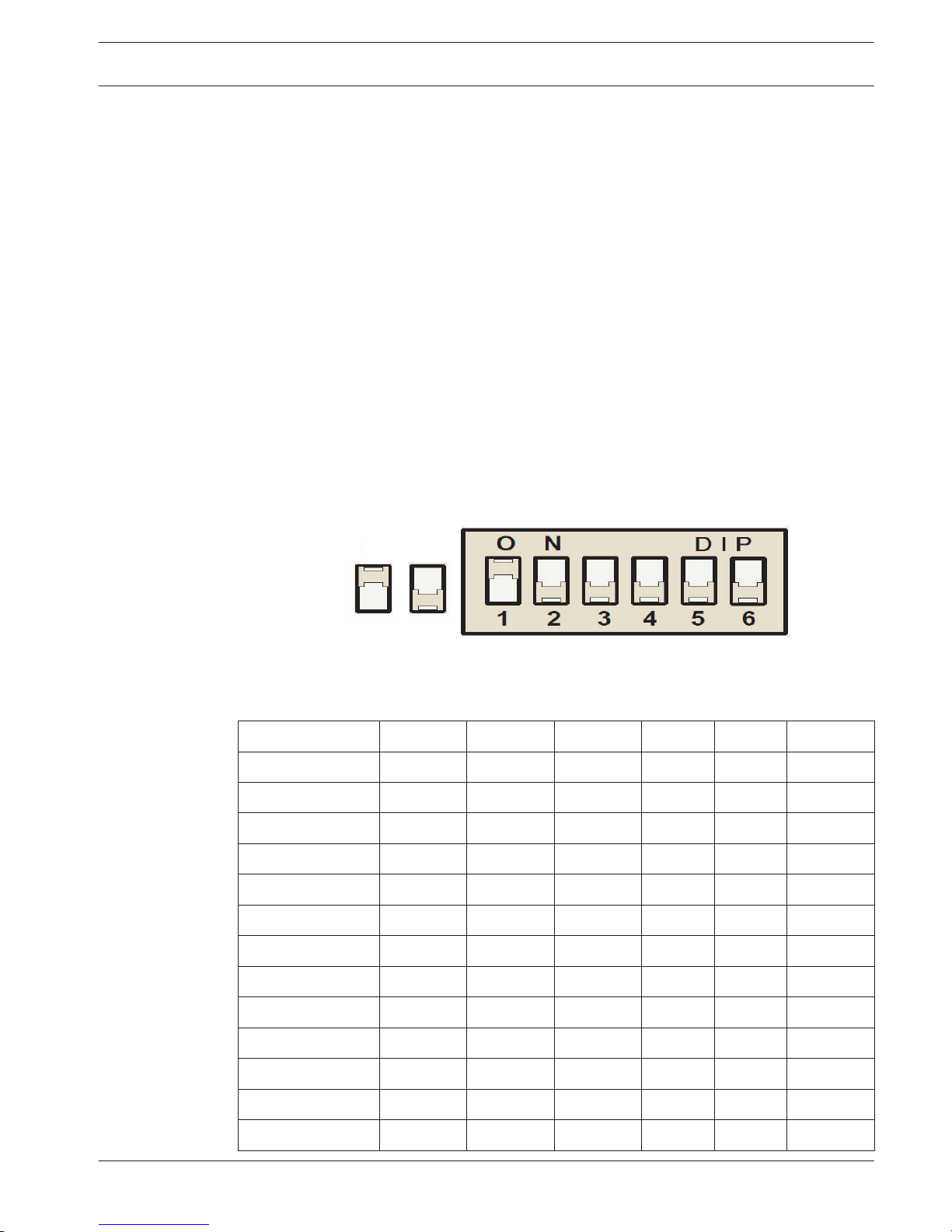
Address Setting
For IUI-AMAX4-TEXT, IUI-AMAX3-LED16, IUI-AMAX3-LED8 keypads, the address of the keypad is
programmed with 6-position DIP switch. See , page 11. The address of each keypad is
unique.
On Off
Figure 5.1: 6-Position DIP Switch
DIP switches 5 and 6 are not used.
DIP Switch
S1 S2 S3 S4 S5 S6
Keypad Address 1 2 3 4 5 6
1 On Off Off Off Off Off
2 Off On Off Off Off Off
3 On On Off Off Off Off
4 Off Off On Off Off Off
5 On Off On Off Off Off
6 Off On On Off Off Off
7 On On On Off Off Off
8 Off Off Off On Off Off
9 On Off Off On Off Off
10 Off On Off On Off Off
11 On On Off On Off Off
12 Off Off On On Off Off
5
5.1
5.1.1
5.1.2
AMAX panel 4000 / AMAX panel 4000
EN
Optional Modules and Peripheral Devices | en 11
Bosch Sicherheitsysteme GmbH Installation Guide 2013.07 | 03 | F.01U.267.112
13 On Off On On Off Off
14 Off On On On Off Off
15 On On On On Off Off
16 Off Off Off Off On Off
Table 5.1: Keypad Address Settings
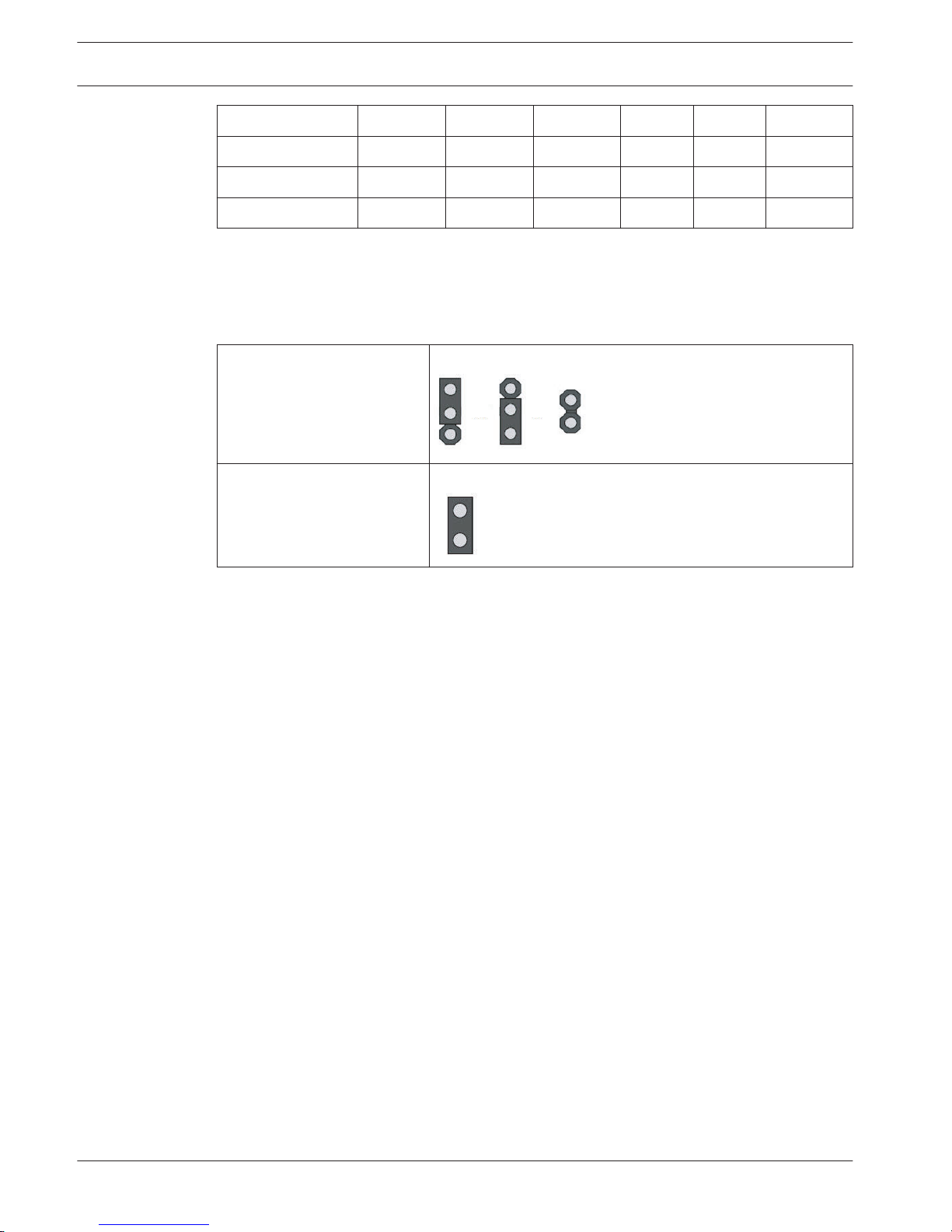
IUI-AMAX-LED8 and IUI-AMAX-LCD8 keypads can only be set to address 1 or address 2 through
the address jumper.
– Jumper not short-circuited: Address 1.
– Jumper short-circuited: Address 2.
Address 1
Jumper not short-circuited:
Address 2 Jumper short-circuited (both metal pins are covered)
Table 5.2: Keypad Jumper Settings
See also
– Keypad Address Settings, page 11
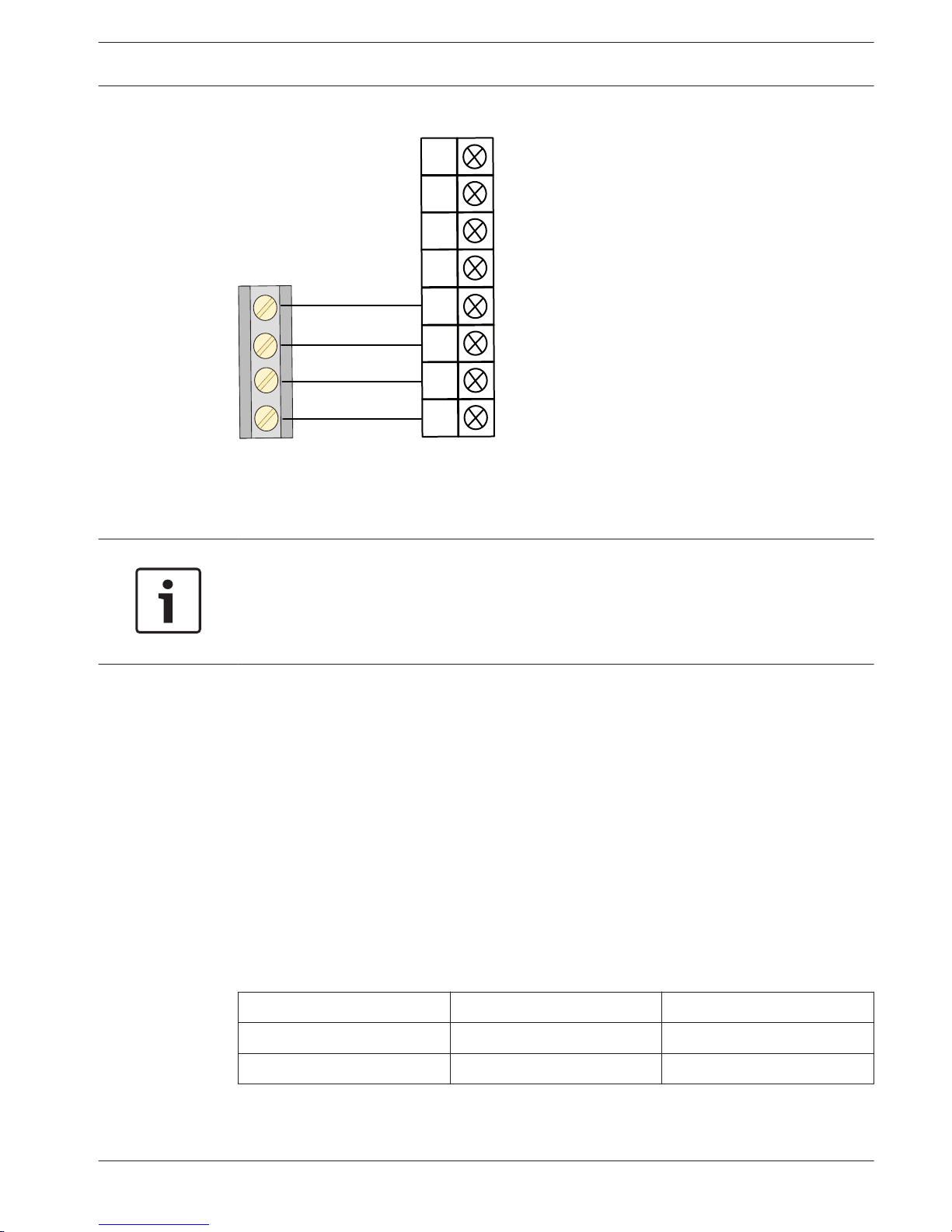
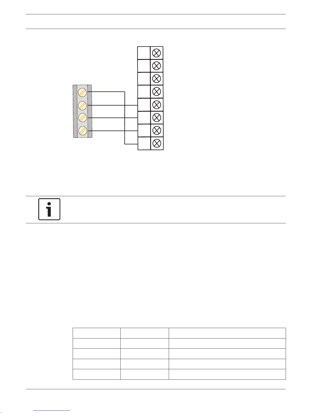
Wiring and Installation
Connect the keypad to the bus of the alarm control panel. See , page 13
– R: provides 12V power supply for the keypad and other devices.
– B: ground conductor.
– G: for the alarm control panel to transmit data to external devices.
– Y: for external devices to transmit data to the alarm control panel.
5.1.3
12 en | Optional Modules and Peripheral Devices
AMAX panel 4000 / AMAX panel 4000
EN
2013.07 | 03 | F.01U.267.112 Installation Guide Bosch Sicherheitsysteme GmbH
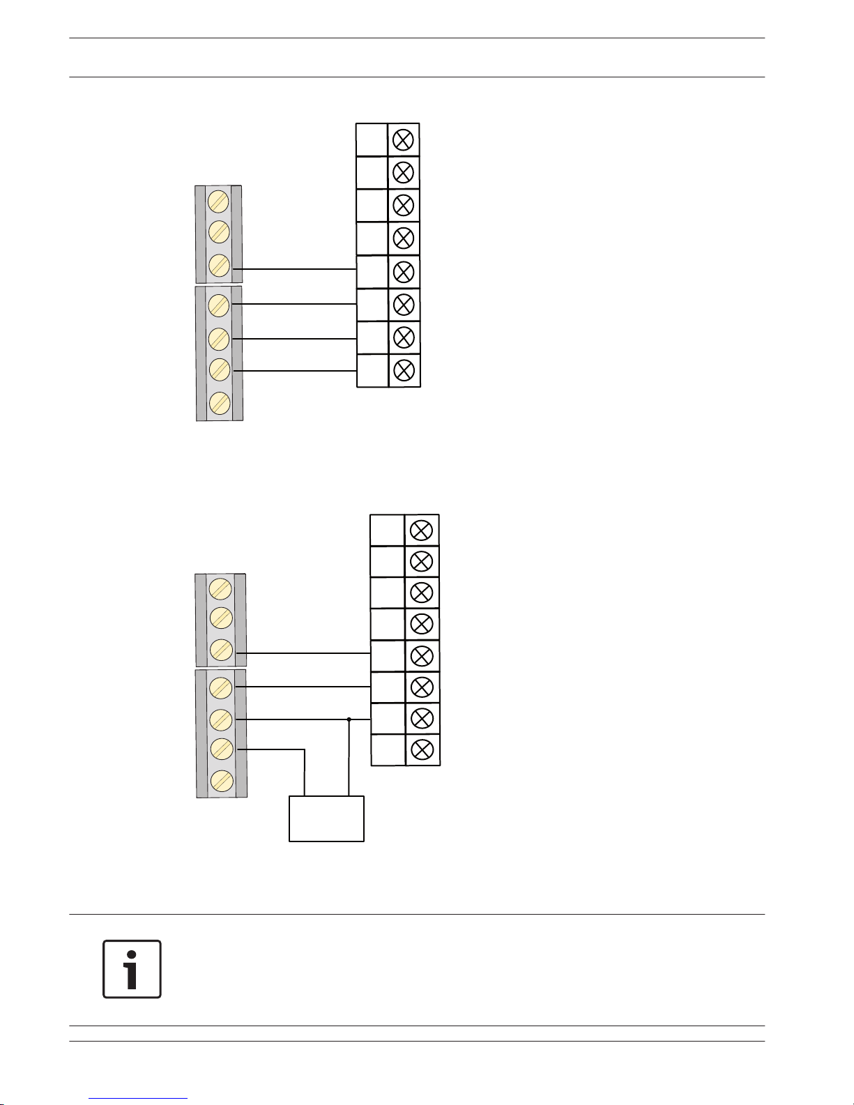
Y
G
B
R
PO 1
R
B
G
Y
Keypad
Yellow
Green
Black
Red
Alarm Control Panel
PO 3
PO 4
PO 2
Figure 5.2: Connecting to the Control Panel
The length of the 0.8mm or 1.0mm cable for connection of a single keypad cannot exceed 200
m.
Notice!
The alarm control panel can connect to up to 16 keypads at the same time, upto 8 wired to
Bosch Option Bus 1 and upto 8 wired to Bosch Option Bus 2. The total length of the cable for
connection of all keypads and expansion module wired to one Bosch Option Bus cannot
exceed 700m.
Test
The alarm control panel tests the communication with the keypad and transmits the keypad
communication failure report in case of failure of communication.
DX2010 Input Expansion Module
Installation
The alarm control panel supports up to six DX2010 input expansion modules. The module is
connected to Bosch option bus 1 or 2. the data bus of the alarm control panel. Each
expansion module supports up to eight zone inputs.
Please refer to , page 28 for more details.
Wiring
Do not use twisted pair or shielded cable to connect DX2010 and the alarm control panel. For
details on length of cable, refer the Table below.
Power Supply Wire diameter of 0.8mm Wire diameter of 1.2mm
External Power Supply 200m 200m
Alarm Control Panel 30m 76m
Table 5.3: Lengths of cable for DX2010
For connecting the DX2010 to the bus of the alarm control panel for power supply, refer to
Figure below.
5.1.4
5.2
5.2.1
5.2.2
AMAX panel 4000 / AMAX panel 4000
EN
Optional Modules and Peripheral Devices | en 13
Bosch Sicherheitsysteme GmbH Installation Guide 2013.07 | 03 | F.01U.267.112
Y
G
B
R
AUX 2+
AUX 2-
AUX 1-
AUX
1+
R
B
G
Y
DX2010
Yellow
Green
Black (-)
Red (+)
Alarm Control Panel
TMPR
1
COM
Figure 5.3: Connecting DX2010 to the Control Panel
For use of external power supply, refer to Figure below.
Y
G
B
R
AUX 2+
AUX
2-
AUX
1-
AUX 1+
R
B
G
Y
DX2010
Ye llow
Green
Black (-)
Red (+)
Alarm Control Panel
TMPR
1
COM
(+)
(-)
12VDC
External Power Supply
Figure 5.4: Connecting DX2010 to the Control Panel with External Power supply
Notice!
The alarm control panel provides 12 VDC power supply with maximum 900mA for each bus or
auxiliary power for the output of external devices.
When the total current of the bus and the auxiliary power supply exceeds 2A, an external
power supply is required.
14 en | Optional Modules and Peripheral Devices
AMAX panel 4000 / AMAX panel 4000
EN
2013.07 | 03 | F.01U.267.112 Installation Guide Bosch Sicherheitsysteme GmbH
Tamper
Each DX2010 module has an onboard tamper and one tamper input, not belonging to zone
inputs.
When the tamper event of DX2010 module occurs, the tamper report is sent with the module
address.
Address Setting
Notice!
When data bus address is changed, the module needs to be re-powered to make the new
address effective.
Each DX2010 module connected to the alarm control panel must have its own data bus
address. Refer to following Table for information.
Module Data Bus Address
DX2010 module 1 (zones 17 - 24) 103
DX2010 module 2 (zones 25 - 32) 104
DX2010 module 3 (zones 33 - 40) 105
DX2010 module 4 (zones 41 - 48) 106
DX2010 module 5 (zones 49 - 56) 107
DX2010 module 6 (zones 57 - 64) 108
Table 5.4: DX2010 Address Settings
For Address DIP switch settings, refer to the followingTable.
DIP Switch
S1 S2 S3 S4 S5 S6
Data Bus Address 32 16 8 4 2 1
103 Off Off Off Off On Off
104 Off Off Off Off On On
105 Off Off Off On Off Off
106 Off Off Off On Off On
107 Off Off Off On On Off
108 Off Off Off On On On
Table 5.5: DX2010 DIP Switch Settings
5.2.3
5.2.4
AMAX panel 4000 / AMAX panel 4000
EN
Optional Modules and Peripheral Devices | en 15
Bosch Sicherheitsysteme GmbH Installation Guide 2013.07 | 03 | F.01U.267.112

Example : Data Bus Location 103 - DIP Settings
On
Off
Figure 5.5: DX2010 DIP Switch Settings
Status Indicator
– Flashing once per second: Indicating normal operation.
– Constant illumination indicates following conditions:
– The grounding conductor is not connected or there is communication failure between the
alarm control panel and the module.
– No zones are distributed to modules with corresponding addresses.
– Module address setting error.
– Off: The module is de-Energized.
DIP Switch
Status Indicator
Figure 5.6: DX2010 Status Indicators
Test
The alarm control panel tests the communication normally with the module. In case of
communication failure, a fault report with the module address is sent.
5.2.5
5.2.6
16 en | Optional Modules and Peripheral Devices
AMAX panel 4000 / AMAX panel 4000
EN
2013.07 | 03 | F.01U.267.112 Installation Guide Bosch Sicherheitsysteme GmbH
DX3010 Output Expansion Module
Installation
The alarm control panel supports up to two DX3010 output expansion modules. The module is
connected to Bosch option bus1 or 2. Each module supports eight fully programmable relay
outputs. Like on-board output, DX3010 can be programmed as the output following the area
such as alarm event, arming / disarming status event and zone alarm event.
For more information about installation, see DX3010 Installation Guide.
Also refer to , page 28 for more details.
Wiring
When the module is placed in the enclosure of the alarm control panel, the power supply for
the control panel or external power supply can be used. For separate installation, the external
power supply must be used.
Power Supply Wire diameter of 0.8mm Wire diameter of 1.2mm
Alarm Control Panel 12.2m 24.4m
External Power Supply 305m 610m
Table 5.6: Lengths of cable for DX3010
For details refer to the Figure below.
Y
G
B
R
AUX 2+
AUX 2-
AUX 1-
AUX 1+
R
B
G
Y
DX3010
Yellow
Green
Black (-)
Red (+)
Alarm Control Panel
Figure 5.7: Connecting DX3010 to the Control Panel
When connecting to an external power supply refer to the following figure.
5.3
5.3.1
5.3.2
AMAX panel 4000 / AMAX panel 4000
EN
Optional Modules and Peripheral Devices | en 17
Bosch Sicherheitsysteme GmbH Installation Guide 2013.07 | 03 | F.01U.267.112
Y
G
B
R
AUX 2+
AUX 2-
AUX 1-
AUX 1+
R
B
G
Y
DX3010
Yellow
Green
Black (-)
Red (+)
Alarm Control Panel
External Power Supply
(+)
(-)
Figure 5.8: Connecting DX3010 to the Control Panel with External Power Supply
Notice!
When the external power supply is used, the black wire (-) is not allowed to be grounded.
Address Setting
Notice!
When data bus address is changed, the module needs to be re-powered to make the new
address effective.
Each DX3010 module connected to the alarm control panel must have its own data bus
address. For details refer to the Table below.
Module Data Bus Address
DX3010 module 1 (Output 5 ~ 12) 150
DX3010 module 2 (Output 13 ~ 20) 151
Table 5.7: DX3010 Address Settings
For Address DIP switch settings, refer to the Table below.
DIP Switch S1 S2 S3 S4 S5 S6
Data Bus Address 1 2 4 8 16 Mode
5.3.3
18 en | Optional Modules and Peripheral Devices
AMAX panel 4000 / AMAX panel 4000
EN
2013.07 | 03 | F.01U.267.112 Installation Guide Bosch Sicherheitsysteme GmbH
150 On On On On On Off
151 Off On On On On Off
Table 5.8: DX3010 DIP Switch Settings
Example : Data Bus Location 150 - DIP Settings
On
Off
Figure 5.9: DX3010 DIP Switch Settings
Test
The alarm control panel tests the communication normally with the module. In case of
communication failure, a fault report with the module address is sent.
B426 Network Interface Module
Brief Introduction
The B426 Ethernet communication module supports monitored two-way IP communication via
Ethernet to perform alarm transmission, remote programming and control of the alarm control
panel.
The alarm control panel supports up to two B426 modules.
Installation
Before installing B426, all power supplies (AC power supply and backup battery power
supply) of the control panel should be disconnected.
Use the standard three-hole installation mode to install B426 in the enclosure of the alarm
control panel case or in another enclosure.
For more information about installation, see B426 Installation and Operating Guide.
Also refer to , page 28 for more details.
Wiring
Connect B426 to Bosch option Bus 1 or 2. The cable may not exceed 150 meters.
5.3.4
5.4
5.4.1
5.4.2
5.4.3
AMAX panel 4000 / AMAX panel 4000
EN
Optional Modules and Peripheral Devices | en 19
Bosch Sicherheitsysteme GmbH Installation Guide 2013.07 | 03 | F.01U.267.112
Y
G
B
R
AUX
2+
AUX
2-
AUX 1-
AUX
1+
R
B
G
Y
B426
Yellow
Green
Black
Red
Alarm Control Panel
Figure 5.10: Connecting B426 to the Control Panel
Address Setting
Turn the rotary switch to 6, i.e., set the address to 134 when the first B426 is used. Turn the
rotary switch to 9, i.e., set the address to 250 when the second B426 is used.
Notice!
When data bus address is changed, the module needs to be re-powered to make the new
address effective.
Configuration
To reconfigure the module or connected to the alarm control panel with RPS, the network or
direct connection must be used to access its built-in Web server.
For more information about configuration, see B426 Installation and Operating Guide.
Status Indicator
B426 provides the following on-board LED indicators to help in troubleshooting.
– Blue system status indicator.
– Green data bus indicator.
– Green Ethernet link indicator.
Refer to the Table below for details.
Color Flash Mode Function
Blue Stable flash Normal operation.
Blue 3 flashes Normal power supply, without communication.
Blue Constant on Failure conditions.
Blue Constant off Power interruption or other failure conditions.
Table 5.9: Functions of B426 System indicators
5.4.4
5.4.5
5.4.6
20 en | Optional Modules and Peripheral Devices
AMAX panel 4000 / AMAX panel 4000
EN
2013.07 | 03 | F.01U.267.112 Installation Guide Bosch Sicherheitsysteme GmbH

For more information about indicators, see B426 Installation and Operating Guide.
Test
The alarm control panel tests the communication normally with the module. In case of
communication failure, a fault report with the module address is sent.
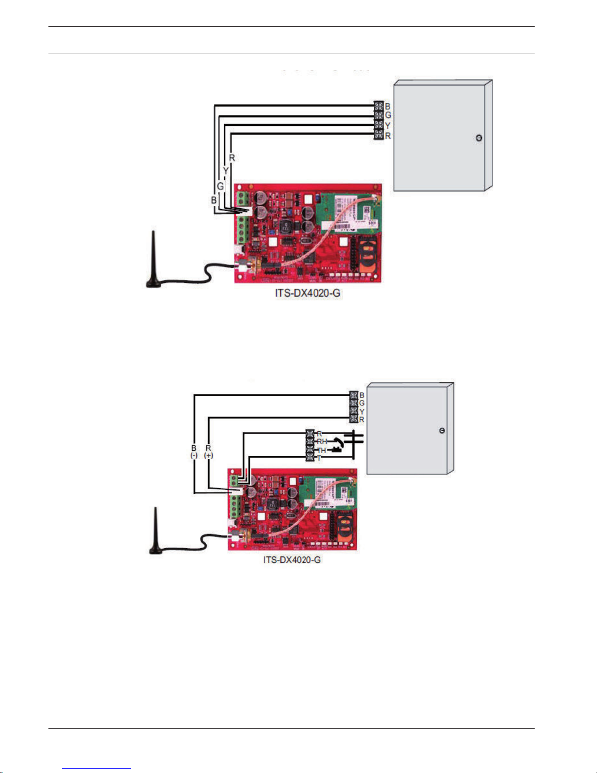
ITS-DX4020-G Communication Module
Brief Introduction
Conettix ITS-DX4020-G GPRS communication module allows IP communication via commercial
GPRS network. Transmission of alarm information via GPRS is the default for ITS-DX4020-G.
SMS or USB mode can be chosen for configuration. The remote programming and control of
the alarm control panel is supported.
The alarm control panel supports up to two communication modules.
– 1 ITS-DX4020-G and 1 B426, or
– 2 B426
Installation
1. Before installing ITS-DX4020-G, all power supplies of the control panel should be
disconnected.
2. Insert SIM card.
3. Use the standard three-hole installation mode to install ITS-DX4020-G in the enclosure of
the alarm control panel or another enclosure.
4. Connect the magnetic antenna ITS-DX4020-G.
Connection
When ITS-DX4020-G is used for communication with the alarm control panel, the bus address
should be set to 134.
The connection of ITS-DX4020-G and the alarm control panel is divided into two modes: GPRS
and GSM.
5.4.7
5.5
5.5.1
5.5.2
5.5.3
AMAX panel 4000 / AMAX panel 4000
EN
Optional Modules and Peripheral Devices | en 21
Bosch Sicherheitsysteme GmbH Installation Guide 2013.07 | 03 | F.01U.267.112
Alarm Control Panel
Figure 5.11: GPRS Mode in Support of IP
Alarm Control Panel
Figure 5.12: GSM Mode in Support of PSTN (Contact ID)
For the status indicator, configuration and more information about ITS-DX4020-G, see
Installation and Operation Guide.
Test
The alarm control panel tests the communication normally with the module. In case of
communication failure, a fault report with the module address is sent.
5.5.4
22 en | Optional Modules and Peripheral Devices
AMAX panel 4000 / AMAX panel 4000
EN
2013.07 | 03 | F.01U.267.112 Installation Guide Bosch Sicherheitsysteme GmbH
RF 3227E RF Receiver
Brief Introduction
The RF3227E RF Receiver allows the use of wireless devices using AMAX panel 4000.
Installation
Considerations
The receiver should be mounted in a central location in regard to all wireless sensors,
whenever possible.
The receiver should be mounted vertically with at least 25 cm clearance above it for the
antennas.
Avoid mounting the receiver in areas with significant metal or electrical wiring such as furnace
rooms or utility rooms. If this is unavoidable, mount the receiver with the antennas extending
above any metal surface.
Avoid mounting the receiver in areas where it may be exposed to moisture.
Reception distances are generally improved with higher mounting locations and with no metal
objects near the antennas.
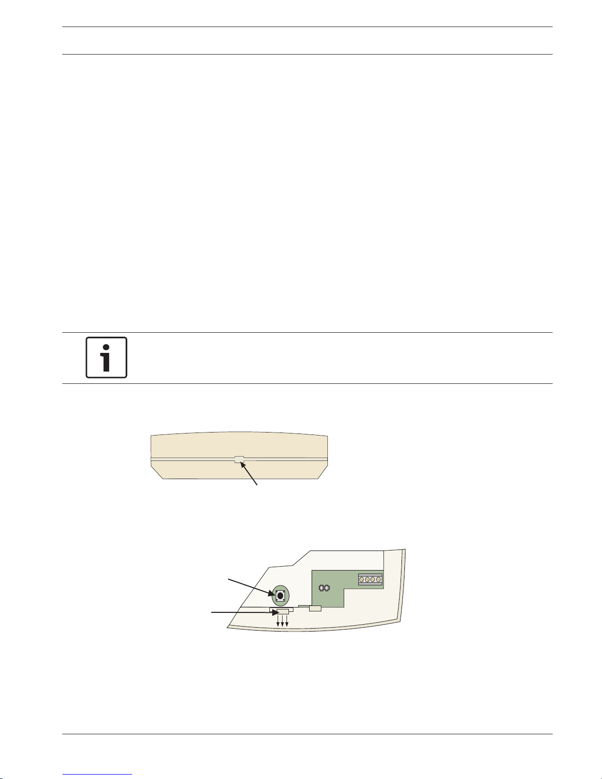
Setting Up the Wall Tamper
Notice!
If not using the wall tamper, proceed to Mounting the Receiver, page 24
To enable the wall tamper switch:
– Remove the cover of the receiver (see Figure 5.13).
Insert screwdriver here and press in.
Figure 5.13: Removing the Cover
– Remove the inner cover by pressing the latch.
Press latch
to remove
the inner cover.
Cover
Tamper
R
B
G
Y
ADDR
Figure 5.14: Removing the Inner Cover
– Move the wall tamper jumper as shown in Figure 5.15.
5.6
5.6.1
5.6.2
AMAX panel 4000 / AMAX panel 4000
EN
Optional Modules and Peripheral Devices | en 23
Bosch Sicherheitsysteme GmbH Installation Guide 2013.07 | 03 | F.01U.267.112

Wall Tamper
Jumper
Wall Tamper disabled
(Default position
)
R
B
G
Y
ADDR
Wall Tamper enabled
Jumper left on pin for storage only.
Figure 5.15: Wall Tamper Jumper
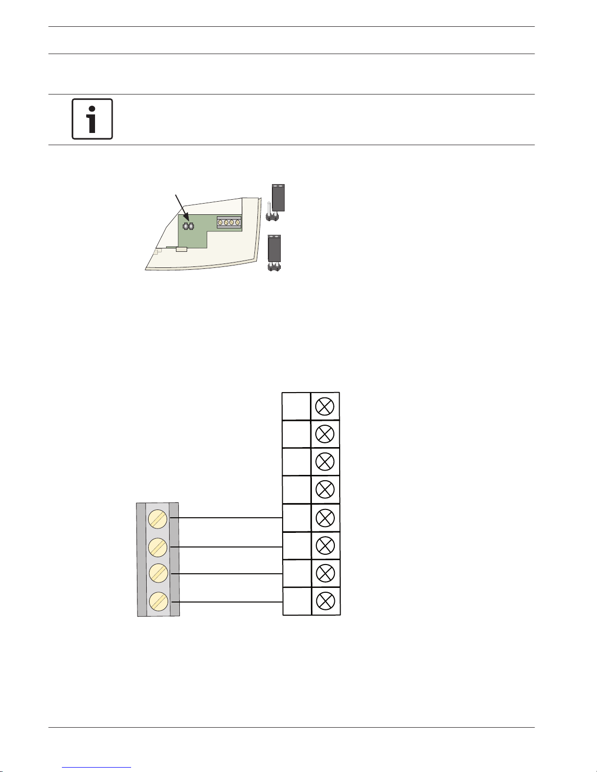
– Replace the inner cover.
– Place the spring from the hardware packet over the shaft of the tamper switch located on
the back of the receiver (see Figure 5.16).
Rear of Receiver
Figure 5.16: Rear of Receiver
Notice!
Cause of Hazard
Gently press the spring onto the tapered shaft. Do not force it down onto the shaft
Mounting the Receiver
• Determine the receiver’s mounting location.
• If not already done, remove the receiver’s cover (as shown in Figure 5.13).
• Place the receiver base on the wall at the desired mounting location and mark the two
mounting holes (see Figure 5.17).
24 en | Optional Modules and Peripheral Devices
AMAX panel 4000 / AMAX panel 4000
EN
2013.07 | 03 | F.01U.267.112 Installation Guide Bosch Sicherheitsysteme GmbH

Bus and Power
Connector
Cover Tamper
Switch
Mounting Holes
LED
R
B
G
Y
ADDR
Antenna Connectors
Figure 5.17: Mounting the Receiver
R
B
G
Y
ADDR
Figure 5.18: Bus and Power Connector
Use one of these
locations for the
antenna.
Preferred Location
Depending on the installation,
this location mighy provide
better performance.
Figure 5.19: Connecting Antennas
AMAX panel 4000 / AMAX panel 4000
EN
Optional Modules and Peripheral Devices | en 25
Bosch Sicherheitsysteme GmbH Installation Guide 2013.07 | 03 | F.01U.267.112
Address Setting
Notice!
When data bus address is changed, the module needs to be re-powered to make the new
address effective.
The receiver address option must have setting, Receiver #1.
AMAX panel 4000 supports Receiver 1 only, Receiver 2 is not supported.
No Jumper = Receiver # 1 (Default)
Jumper = Receiver # 2
Address Jumper
Jumper left on pin for storage only.
R
B
G
Y
ADDR
Figure 5.20: Address
Wiring
Connect RF3227E receiver to Bosch option Bus 1 or 2. The cable may not exceed 300 m.
Adding additional devices to the bus might reduce the maximum distance. Shielded cable is
not required. Do not use twisted pair wire.
Y
G
B
R
AUX 2+
AUX 2-
AUX 1-
AUX 1+
R
B
G
Y
RF3227E
Yellow
Green
Black (-)
Red (+)
Alarm Control Panel
Figure 5.21: Connecting RF3227E
5.6.3
5.6.4
26 en | Optional Modules and Peripheral Devices
AMAX panel 4000 / AMAX panel 4000
EN
2013.07 | 03 | F.01U.267.112 Installation Guide Bosch Sicherheitsysteme GmbH
Status Indicator
Table describes the receiver’s status based on the LED condition.
LED Condition Indicates
On The receiver is functioning normally.
Off A power failure occurred or the receiver is not correctly
wired.
Turns on momentarily The receiver acknowledged receiving a message from a
compatible transmitter
Flashes rapidly for less than one
minute
The receiver is being programmed with zone and
transmitter IDs from the compatible panel. This condition
occurs at system initialization (power up) or when new
zone information is programmed into the system. The rapid
flashing lasts less than one minute.
Flashes rapidly for more than
one minute
The receiver failed power-up self tests. Replace the
receiver
RFRC-OPT Radion Receiver
General Information
The RFRC Opt Radion Receiver allows the use of wireless devices using AMAX panel 4000.
Installation
Address Setting
AMAX 4000 panel supports one receiver only.
Wiring
Connect RFRC - OPT Radion Receiver to Bosch opton Bus 1 or 2.
Status Indicator
Remote Programming Software
It can be remotely connected to the software ITS-A-LINK PLUS developed by Bosch or the
third-party software integrated with BOSCH SDK to program the alarm control panel. The
software can access all the options and functions and manage and maintain event records and
service reports.
For more information about ITS-A-LINK PLUS, see User Guide.
Programming Key / Firmware Upgrade Key
The programming key can copy and store all programming information in the alarm control
panel. Firmware Upgrade Key is used for firmware upgrade.
5.6.5
5.7
5.8
5.9
AMAX panel 4000 / AMAX panel 4000
EN
Optional Modules and Peripheral Devices | en 27
Bosch Sicherheitsysteme GmbH Installation Guide 2013.07 | 03 | F.01U.267.112
Installation
This chapter specifies installation and system power up of the AMAX panel 4000.
This system / product must be installed by a qualified installer / service person.
During installation and wiring, the control panel power source must be switched-off to prevent
equipment damage.
– To switch off the Power Source, an easy accessible circuit breaker must be available.
– The System / product must be connected to a socket-outlet with a protective earthing
contact
The User has to disconnect all Telecommunication Network Connectors before unplug the
power adaptor.
After the control panel wiring is completed, connect the AC power and backup batteries.
The power light on the keypad will light to show that AC power is connected.
Notice!
- Use only non spillable battery
- Battery must be recycled
- When battery is not replaced correctly, risk of fire explosion or burning
- Replace the battery every 3-5 years under normal conditions of use.
- Place a Label with change date on the battery
Notice!
The system must be installed and maintained by qualified installer / service person.
Bosch recommends testing the whole alarm system at least once a week.
Maintenance should be done by qualified installer / service person four times a year.
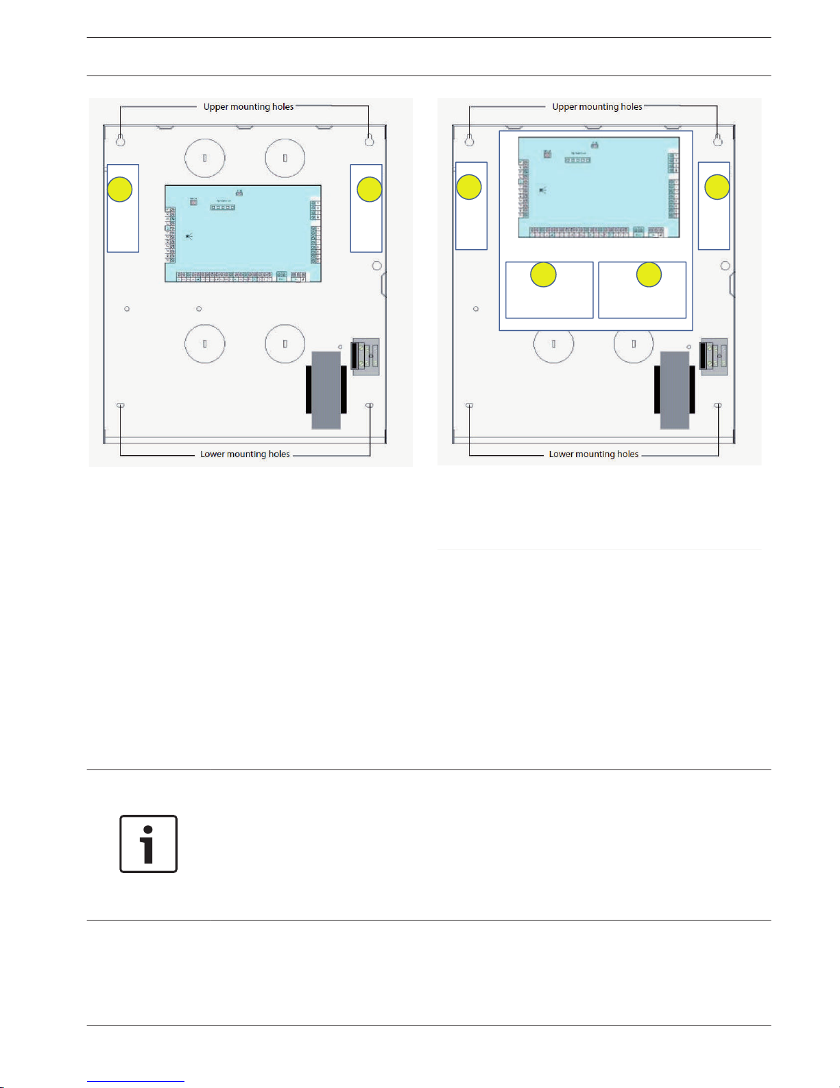
Module Installation
The enclosure contains only PCBs and transformers of the fixed alarm control panel, not other
hardware for installation.
1. Open the knockout holes for wiring in the module.
2. Position two upper mounting holes on the installation wall with the module.
3. Pre-install screws on the mounting holes (provided by the installer).
4. Mount the screws on the module.
5. Fasten the screws.
6. Fix the two lower mounting holes with screws.
Notice!
Please choose appropriate positioning screw kit when installed in a non-load-bearing wall.
6
6.1
28 en | Installation
AMAX panel 4000 / AMAX panel 4000
EN
2013.07 | 03 | F.01U.267.112 Installation Guide Bosch Sicherheitsysteme GmbH
1 2
3 4
E N √ E N √
1 2
Enclosure - Standard
6.2 Enclosure with mounting plate
Enclosure with mounting plate
Figure 6.1: Enclosure / with mounting plate
Expansion modules can be placed in enclosure of the alarm control panel. Several places are
available. Figure 6.1. shows standard enclosure installation and enclosure installation with
mounting plate
Battery Installation
The system supports one sealed lead-acid rechargeable battery. After fully charged, the
battery can be used as a backup power supply to support the system.
Please refer to , page 171
Notice!
- Use only non-spillable battery
- Battery must be recycled
When battery is not replaced correctly
- Risk of fire explosion or burning.
Replace the battery every 3-5 years under normal conditions of use. Label on the battery the
date each time a new battery is installed.
6.2
AMAX panel 4000 / AMAX panel 4000
EN
Installation | en 29
Bosch Sicherheitsysteme GmbH Installation Guide 2013.07 | 03 | F.01U.267.112
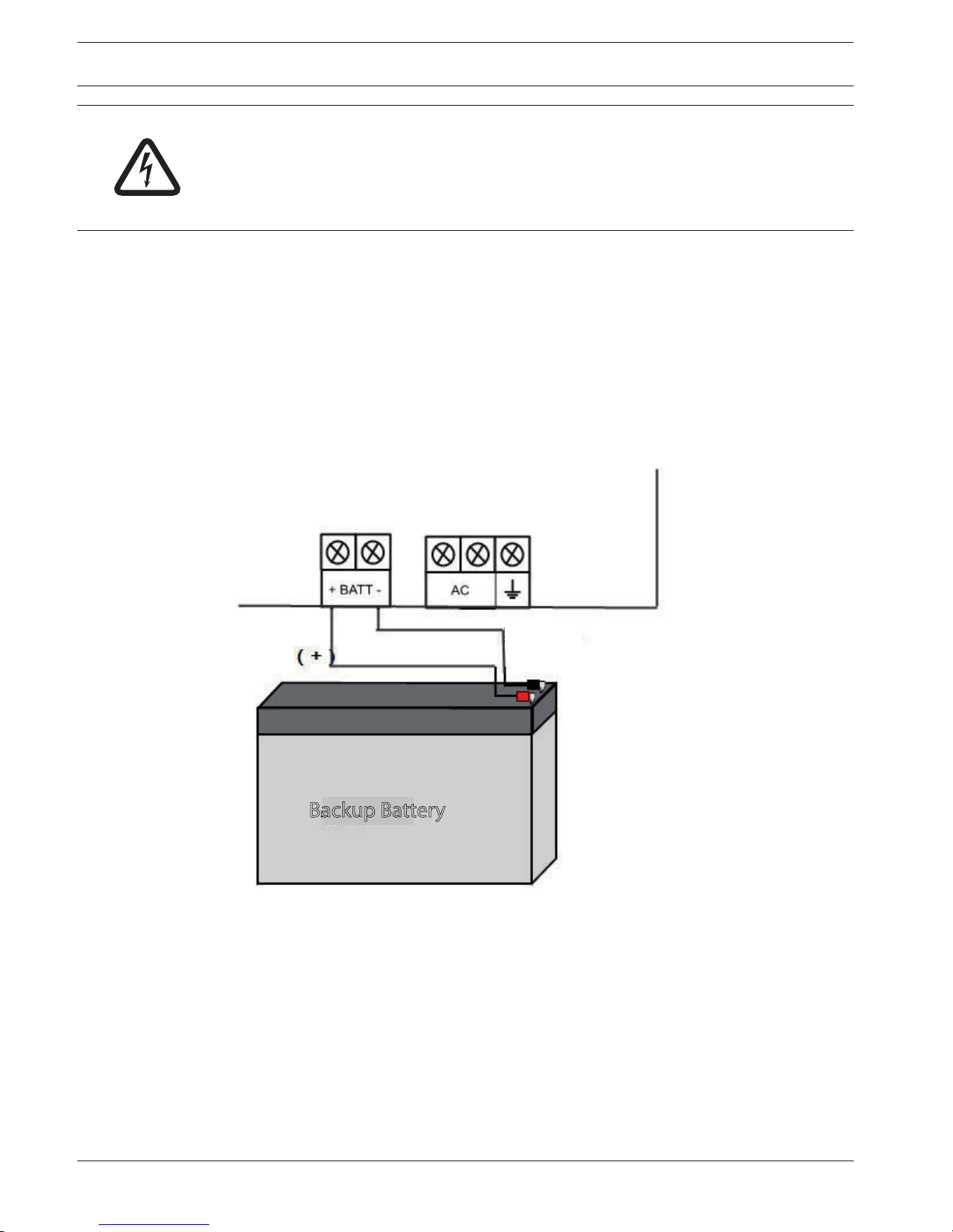
Danger!
Special care is required in connecting the positive (red) wire and the “BATT +” port of the
alarm control panel. If short-circuiting with the “BATT +” port of the alarm control panel or the
enclosure, electric arc will occur. To remove the battery from the control panel, the positive
wire of the battery should be disconnected first.
1. Place the battery on the bottom of the module.
2. Position the red and black wires supplied with the battery.
3. Connect one end of the black wire to the "BATT -" port of the alarm control panel, the
other end to the negative (-) pole of the battery.
4. Connect one end of the red wire to the "BATT +" port of the alarm control panel, the
other end to the positive (+) pole of the battery.
After the backup battery and the main power are connected, once the installation is
completed, the alarm control panel will began to charge the battery.
Red Lead
Black Lead ( - )
Backup Battery
Figure 6.2: Connection of Battery
System Power Up
After the system is powered up, set date and time. Otherwise, the system prompts as fault.
After the system is powered up or reset, it resets to previous arming / disarming status.
To reduce false alarms caused by system power-up (or by power supply restoration after both
mains supply and AUX power supply fail), the system is designed to not perform zone test
within one minute after power-up.
6.3
30 en | Installation
AMAX panel 4000 / AMAX panel 4000
EN
2013.07 | 03 | F.01U.267.112 Installation Guide Bosch Sicherheitsysteme GmbH
 Loading...