

Bosch ICP-AMAX4-P1, ICP-AMAX4-P2-EN, ICP-AMAX-P3-EN, AMAX 4000, AMAX 4000EN Installation Manual
Page 1
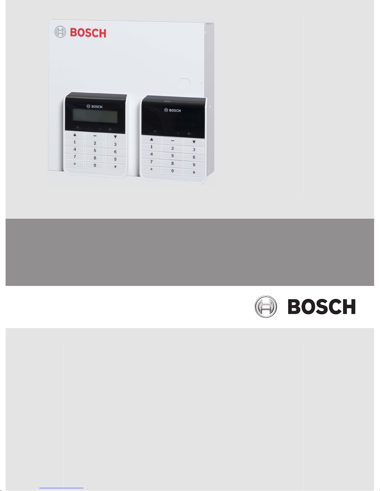
AMAX panel 4000 / AMAX panel 4000 EN
ICP-AMAX4-P1 / ICP-AMAX4-P2-EN / ICP-AMAX-P3-EN
en Installation Guide
Page 2

Page 3

Table of contents
1
Graphics 6
2
Safety 8
3
Short Information 9
4
System overview 10
5
Optional Modules and Peripheral Devices 11
5.1 Bosch Option Bus 11
5.2 Keypad 12
5.2.1 General 12
5.2.2 Address Setting 12
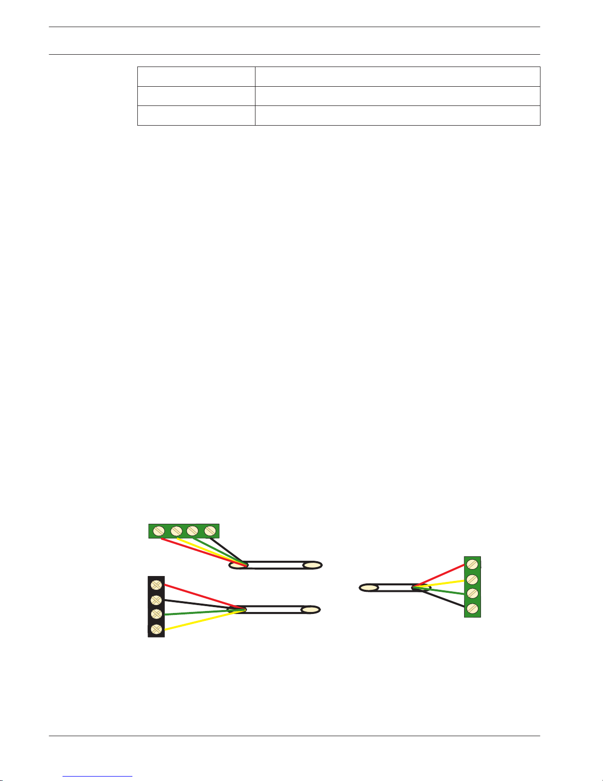
5.2.3 Wiring 13
5.2.4 Status Indicator 13
5.3 DX2010 13
5.3.1 General 13
5.3.2 Address Setting 14
5.3.3 Wiring 14
5.3.4 Status Indicator 15
5.4 DX3010 15
5.4.1 General 15
5.4.2 Address Setting 15
5.4.3 Wiring 16
5.4.4 Status Indicator 16
5.5 B426 17
5.5.1 General 17
5.5.2 Address Setting 17
5.5.3 Wiring 17
5.5.4 Status Indicator 17
5.6 DX4020-G 18
5.6.1 General 18
5.6.2 Address Setting 18
5.6.3 Wiring 18
5.6.4 Status Indicator 19
5.7 RF 3227E RF 19
5.7.1 General 19
5.7.2 Address Setting 19
5.7.3 Wiring 20
5.7.4 Status Indicator 21
5.8 RF Radion Receiver 21
5.8.1 General 21
5.8.2 Address Setting 21
5.8.3 Wiring 21
5.8.4 Status Indicator 21
6
Installation 23
6.1 Module Installation 23
6.2 Battery Installation 24
6.3 System Power Up 25
6.4 System Status Indicator 25
6.5 Prerequisites for Certification conform Installation 26
AMAX panel 4000 / AMAX panel 4000
EN
Table of Contents | en 3
Bosch Sicherheitssysteme GmbH Installation Guide 2014.4 | 01 | F.01U.267.112
Page 4

6.5.1 EN 50131-3 Grade 2, Environmental Class 2 - AMAX 2100 / 3000 / 4000 26
6.5.2 NFA2P AFNOR / CNPP - AMAX 4000 28
6.5.3 INCERT - AMAX 4000 28
6.5.4 SFF – AMAX 2100 / 3000 / 4000 29
7
Settings 30
7.1 Communication and Reporting 30
7.1.1 Receivers 30
7.1.2 Reports 36
7.1.3 Automatic Test Report 40
7.1.4 Dual IP 40
7.1.5 Remote Access 40
7.1.6 Remote PC 41
7.1.7 Call back and Domestic Call 41
7.1.8 Ring Times 42
7.2 Codes 42
7.2.1 User Code and Code Commands 42
7.2.2 Installer Code 46
7.2.3 Code Length 46
7.2.4 Code Reporting 46
7.2.5 Code Permissions 47
7.3 Zones 47
7.3.1 Add / Delete Zone 47
7.3.2 Pulse Count Duration 55
7.3.3 Cross Zone Timer 55
7.3.4 Zone Function Settings 55
7.3.5 Zone Indication Keypad and Event Log 59
7.4 Keypads and Areas 60
7.4.1 Keypad Area 60
7.4.2 Area Timing 61
7.4.3 Common Area 61
7.4.4 Keypad Tone / Lockout 61
7.5 System 61
7.5.1 System Setting 61
7.5.2 System View 63
7.6 Outputs and Sirens 66
7.6.1 Outputs 66
7.6.2 Sirens 72
7.7 RF Devices 72
7.7.1 RF Options 72
7.7.2 RF Devices / User 73
7.8 Address and Key Programming 74
7.8.1 Address Programming 74
7.8.2 Programming with the ICP-EZPK Programming Key 74
8
Configuration 76
8.1 Programming with the Keypad 76
8.1.1 Text Keypad Menu Programming 76
8.1.2 LED/LCD Keypad Programming 84
8.2 PC Programming 85
8.2.1 Direct Connection 86
4 en | Table of Contents
AMAX panel 4000 / AMAX panel 4000
EN
2014.4 | 01 | F.01U.267.112 Installation Guide Bosch Sicherheitssysteme GmbH
Page 5

8.2.2 Modem Connection 88
8.2.3 IP Connection 91
9
Address Programming 95
9.1 Communication and Reports Setting 95
9.2 Zone Programming 101
9.3 Output Programming 114
9.4 Access Codes 119
9.5 System Programming 121
10
Troubleshooting 138
10.1 General Trouble 138
10.2 Trouble Fault Inquiry 140
11
Maintenance 150
11.1 Firmware Upgrade with the ICP-EZRU2 Upgrade Key 150
12
Technical Data 151
AMAX panel 4000 / AMAX panel 4000
EN
Table of Contents | en 5
Bosch Sicherheitssysteme GmbH Installation Guide 2014.4 | 01 | F.01U.267.112
Page 6
Graphics
Pro
gram Key Port
GND
-
+
A C
A
C
Transformer
Battery
Tam
per
L2 COM
COM
COM
L1a
L3
L4
L5
L6
L7
L8
L9
COM
COM
COM
COM
L10
L11
L12
L13
L14
L15
L16
P0+4
R
B
G
Y
AUX1
-
AUX2
-
AUX1
+12V
Y
G
B
R
RINGRHTHTIP
L1b
P0+3
P0+
P0-2
P0-1
Zones
Bosch Option
Bus 2 < 900mA
+12V
+
0 V
1
2
3
3
1 Tamper Switch
2 Zone Switch
3 EOL 2,2 k
3
2
3
2
Fuse 1 A
PO+4: < 750mA
PO+3: < 750mA
PO -2: < 500mA
PO -1: < 500mA
230V ~50Hz
230mA
Wac
hdog
outpu
t
<100
mA
12V < 18Ah
18VAC@50VA
Zones
AUX 1: < 900mA
AUX 2: < 900mA
AUX Power
Fir
e
Intrusion
Risk of shock if N,L1 or is connected incorrectly.
For operation safety, the ground terminals must
be connected.
3
3
2
Slow flash: Normal state
On: Trouble state
Off: Trouble state
_
_
_
_
_
_
_
_
+12V
+12V
+12V
COM
_
12V 7Ah
AUX2
+12V
_
COM
supervised
PO-5
Z1
2
2
3
3
Keypads:
IUI-AMAX4-TEXT
IUI-AMAX3-LED16
IUI-AMAX3-LED8
Keypads:
IUI-AMAX-LED8
IUI-AMAX-LCD8
I/O Moduls:
DX2010 Adr. 103 - 108
DX3010 Adr. 150 - 151
DX4010 Adr. 253
Communicators:
DX4020G Adr. 134
B426 Adr. 134(6) / 250(9)
RF Receiver:
RF3227E 1=
RFRC-OPT 1= (1)
1 =
2
=
3 =
4
=
1 =
2 =
Bosch Option
Bus
1 < 900
mA
COM
R
B
G
Y
R
B
G
Y
R
B
G
Y
♥
IUI-AMAX3
+4 Keypad
3
1
2
1
Facto
ry
Default
5-16 Inst. Guide
I
2000mA
100 Ω - 2,2 k
_
<
∑
3
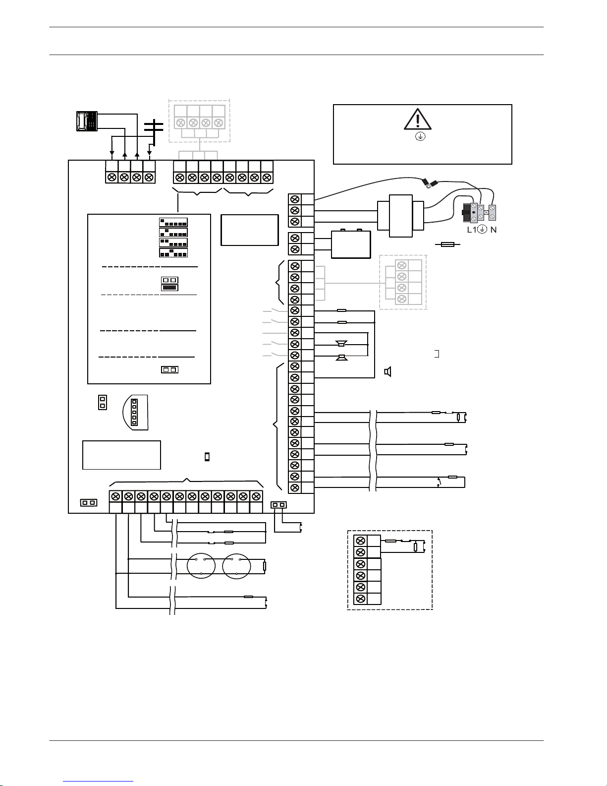
Figure 1.1: AMAX 4000
1
6 en | Graphics
AMAX panel 4000 / AMAX panel 4000
EN
2014.4 | 01 | F.01U.267.112 Installation Guide Bosch Sicherheitssysteme GmbH
Page 7
Program Key P
ort
GND
-
+
AC
Transformer
Battery
Tam per
L8
12V
R
B
G
Y
1RING
TIP
P0+
P0-2
P0-1
1 Tamper Switch
2 Zone Switch
3 EOL 2,2 k
Fuse 500 mA
PO -2: < 500mA
PO -1: < 500mA
230V ~50Hz
85mA
18V-22V@20VA
Risk of shock if N,L1 or is connected incorrectly.
For operation safety, the ground terminals must
be connected.
Slow flash: Normal state
On: Trouble state
Off: Trouble state
_
_
12V 7Ah
supervised
Z1
Keypads:
IUI-AMAX4-TEXT
IUI-AMAX3-LED16
IUI-AMAX3-LED8
Keypads:
IUI-AMAX-LED8
IUI-AMAX-LCD8
I/O Moduls:
DX2010 Adr. 102 - 105
DX3010 Adr. 150 - 151
DX4010 Adr. 253
Communicators:
DX4020G Adr. 134
B426 Adr. 134(6) / 250(9)
RF Receiver:
RF3227E 1=
RFRC-OPT 1= (1)
1 =
2
=
3 =
4
=
1
=
2
=
COM
R
B
G
Y
R
B
G
Y
♥
IUI-AMAX3 +4 Keypad
3
1
2
Factory
Default
5-8 Inst. Guide
I
1100mA
100 Ω - 2,2 k
_
<
∑
3
TIP
COM
L7
L6
COM
L5
COM
L4
L3
L2
COM
L1
AC
Zones
+12V
COM
COM
1
2
3
3
3
2
3
2
1
_
Bosch Option
Bus 1 < 500mA
OPT/SDI
COM
B
A
PWR
1RING
_
Rel
ay
PO-3: < 100mA
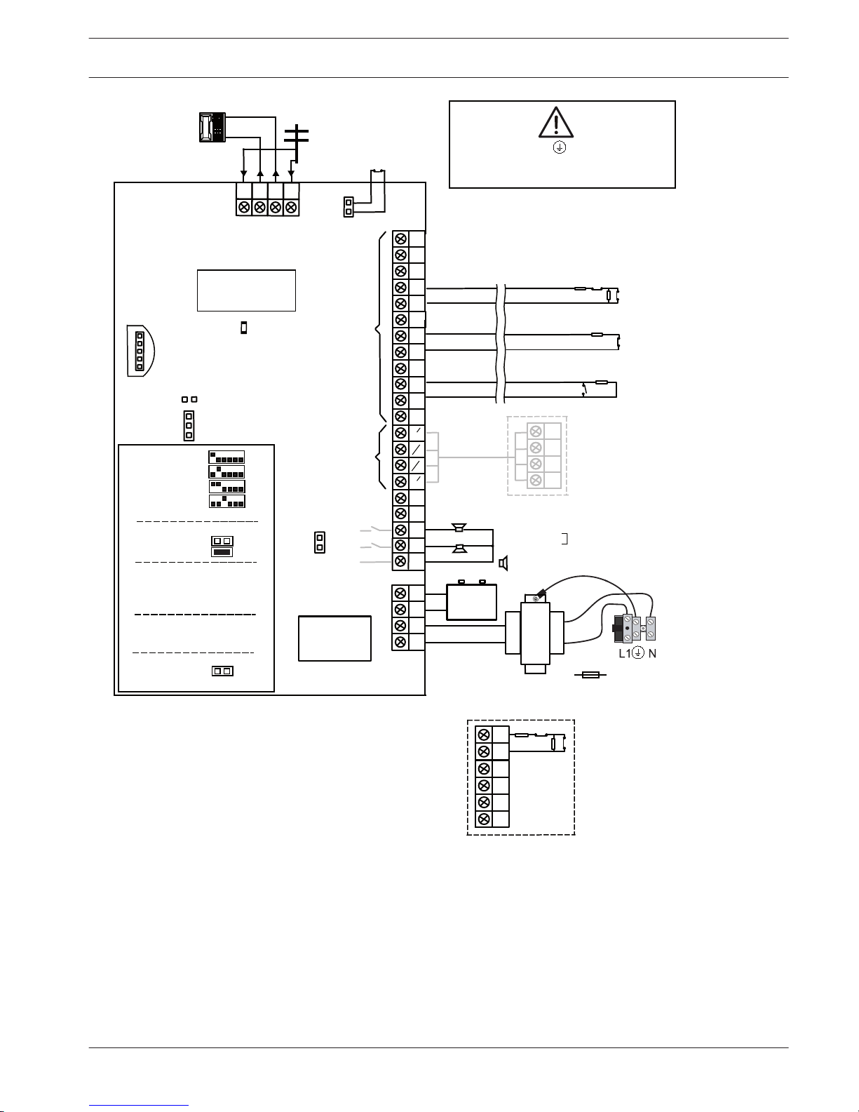
Figure 1.2: AMAX 2100/3000
AMAX panel 4000 / AMAX panel 4000
EN
Graphics | en 7
Bosch Sicherheitssysteme GmbH Installation Guide 2014.4 | 01 | F.01U.267.112
Page 8
Safety
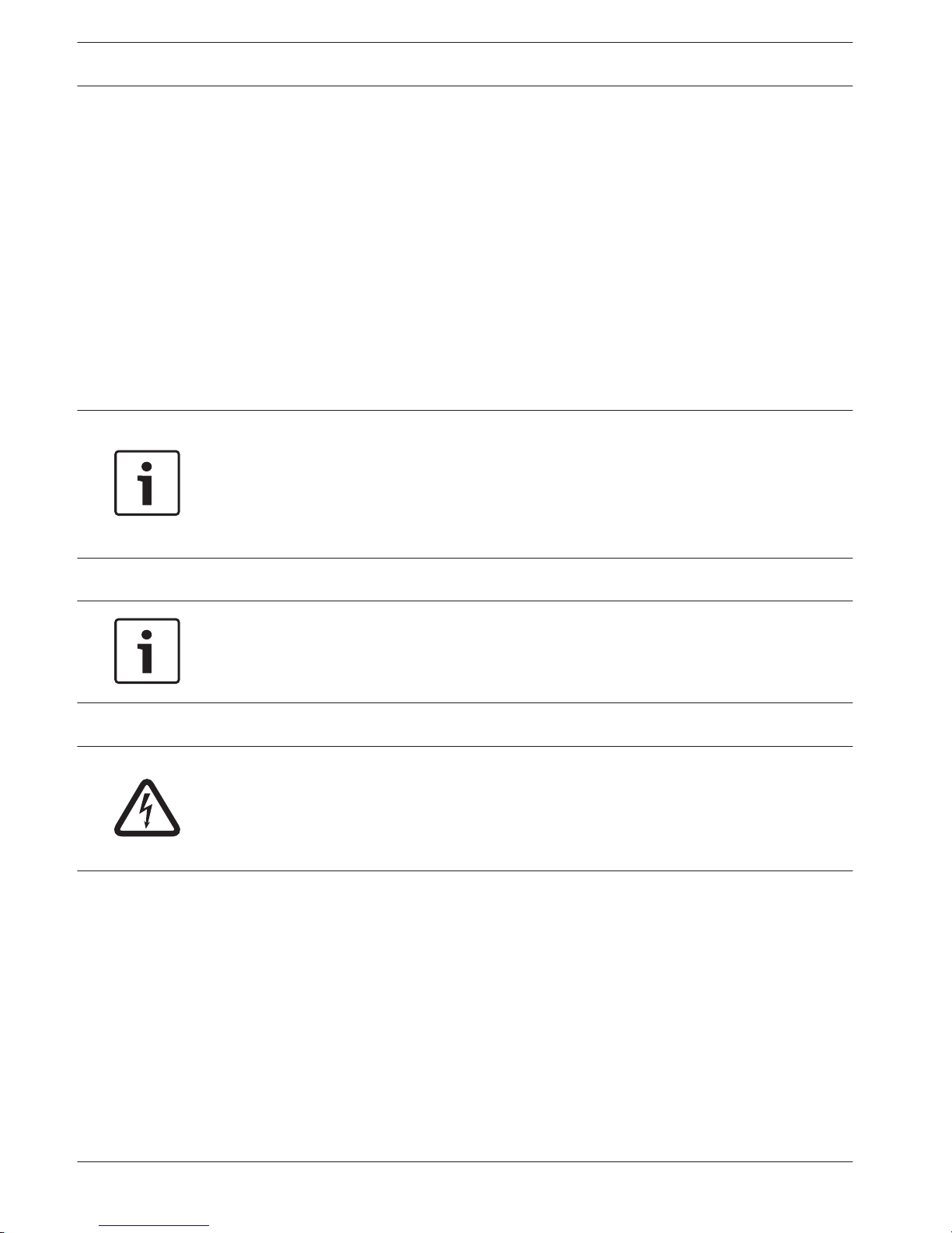
This system / product must be installed by a qualified installer / service person.
During installation and wiring, the AMAX power source must be switched off to prevent
equipment damage.
– To switch off the power source, an easy accessible circuit breaker must be available
– The system / product must be connected to a socket-outlet with a protective earthing
contact
The User has to disconnect all Telecommunication Network Connectors before unplugging the
power adaptor.
After the AMAX panel wiring is completed, connect the AC power and backup batteries.
The mains indicator on the keypad will light up show that AC power is connected.
Notice!
- Use only non spillable battery
- Battery must be recycled
- When battery is not replaced correctly, risk of fire explosion or burning
- Replace the battery every 3-5 years under normal conditions of use
- Place a label with change date on the battery
Notice!
- The system / product must be installed and maintained by qualified installer / service
person.
- Bosch recommends testing the alarm system at least once a week.
Danger!
As static-sensitive components are included in PCBs, anti-static steps should be followed and
they should be carefully installed.
Before installing the alarm AMAX panel, the static electricity should be discharged by
connecting the grounding terminal of the AMAX panel.
2
8 en | Safety
AMAX panel 4000 / AMAX panel 4000
EN
2014.4 | 01 | F.01U.267.112 Installation Guide Bosch Sicherheitssysteme GmbH
Page 9

Short Information
Congratulations on selecting the AMAX panel for your installation. Spend some time reading
through this guide and familiarize yourself with the outstanding installation and operation
features of this system so that you can get the most from your unit. In all aspects of planning,
engineering, styling, operation, convenience, and adaptability, we try to anticipate your every
possible requirement. Programming simplicity and speed are our major considerations. We
believe that our objectives have been attained. This installation guide explains all aspects of
programming the AMAX panel from factory default to final commissioning. All system
parameters and options are dealt with in detail, but, adaptability differs with individuals. Each
AMAX panel can be tailored to meet your requirements quickly and easily. The programming
simplicity makes your installation quick, accurate, and rewarding.
3
AMAX panel 4000 / AMAX panel 4000
EN
Short Information | en 9
Bosch Sicherheitssysteme GmbH Installation Guide 2014.4 | 01 | F.01U.267.112
Page 10
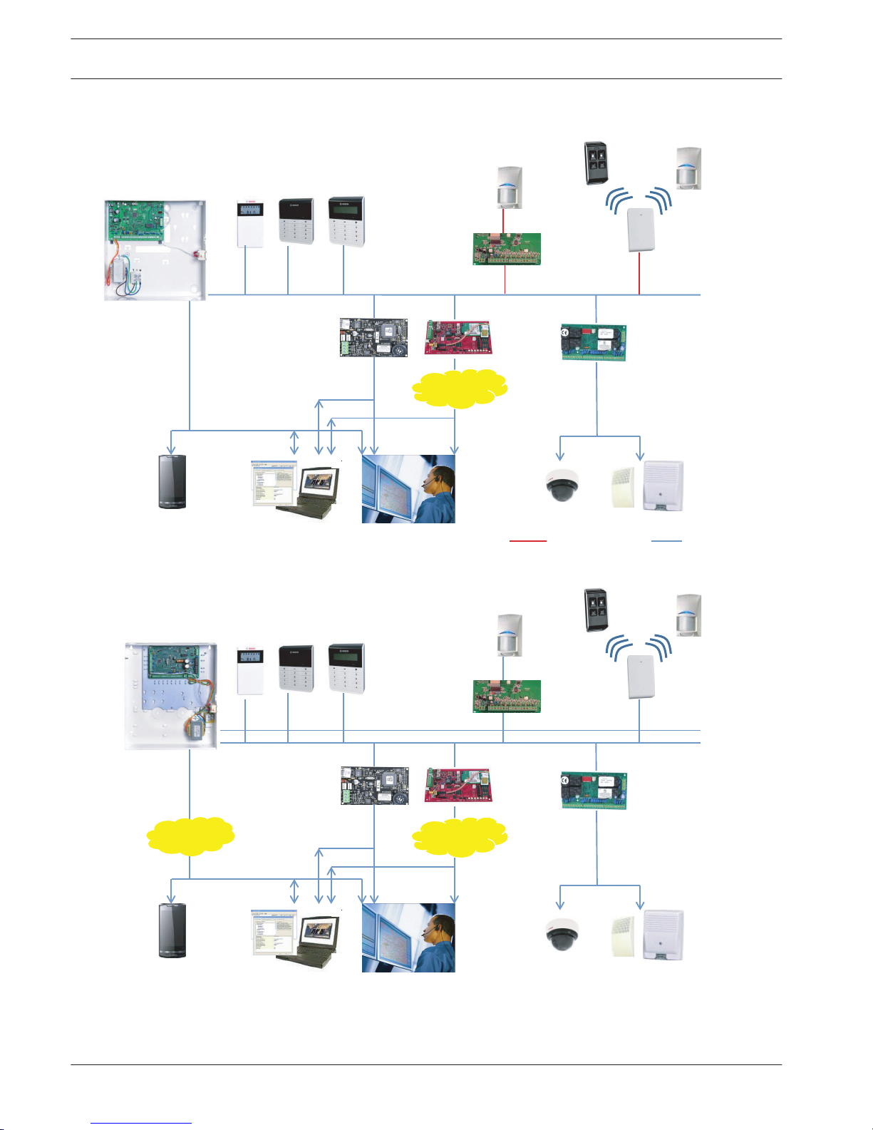
System overview
DX2010
Option Bus
B426
A Link Plus
CMS
IP
Video
DX4020G
PSTN
GSM/
GPRS
AMAX 3000 AMAX 2100 / 3000
Radion
DX3010
Text KeypadLCD / LED Keypad
AMAX 3000
AMAX 3000
Figure 4.1: AMAX 2100/3000 Overview
DX2010
Option Bus
B426
A Link Plus
CMS
IP
Video
DX4020G
PSTN
GSM/
GPRS
Radion
DX3010
Text KeypadLCD / LED Keypad
Figure 4.2: AMAX 4000 Overview
4
10 en | System overview
AMAX panel 4000 / AMAX panel 4000
EN
2014.4 | 01 | F.01U.267.112 Installation Guide Bosch Sicherheitssysteme GmbH
Page 11
Optional Modules and Peripheral Devices
Bosch Option Bus
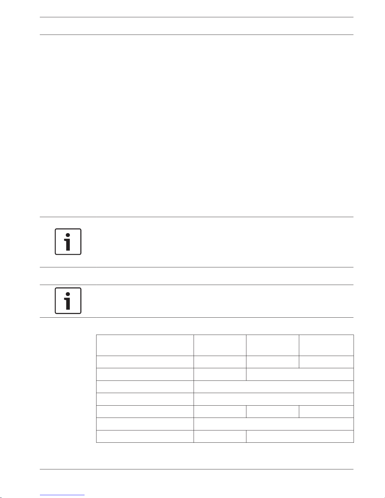
The AMAX panel provides the Bosch Option Bus to attach expansion modules. AMAX 2100 /
3000 each has one (Bosch Option Bus 1) and AMAX 4000 has two (Bosch Option Bus 1 and
2).
Maximum 14 modules (8 keypads) can be connected to each bus. The total length of the cable
for connection of all keypads and expansion modules wired to one Bosch Option Bus must not
exceed 700m. Particular modules require limitation in cable distance, f.e. the last keypad must
be placed within 200m.
The AMAX panel tests the communication with the modules and transmits the communication
failure report in case of failure of communication.
Cable Details:
– R: AUX 12V +
– B: 12V –
– G: Data
– Y: Data
Notice!
The AMAX panel 2100 / 3000 provides 12 VDC power supply with maximum 500mA for Bosch
option bus 1. The AMAX panel 4000 provides a maximum 900mA for each Bosch option bus 1
and 2. When the total current of the bus exceeds the limit, an external power supply is
required.
Notice!
When data bus address is changed, the module needs to be re-powered to make the new
address effective.
Bosch Option Bus Module –
AMAX Panel
2100 3000 4000
Keypads 4 8 16
DX3010 1 2
B426 or DX4020 2 / 1 if DX4020G is used
DX4020G 1
DX2010 3 6
DX4010 1
RF receiver 1
Table 5.1: AMAX panel number of Bosch Option Bus modules
5
5.1
AMAX panel 4000 / AMAX panel 4000
EN
Optional Modules and Peripheral Devices | en 11
Bosch Sicherheitssysteme GmbH Installation Guide 2014.4 | 01 | F.01U.267.112
Page 12
Keypad
General
AMAX panel supports five types of keypad as follows:
– IUI-AMAX4-TEXT (LCD Text Keypad)
– IUI-AMAX3-LED16 (16 Zone LED Keypad)
– IUI-AMAX3-LED8 (8 Zone LED Keypad)
– IUI-AMAX-LED8 (8 Zone LED Keypad)
– IUI-AMAX-LCD8 (8 Zone LCD Keypad)
Address Setting
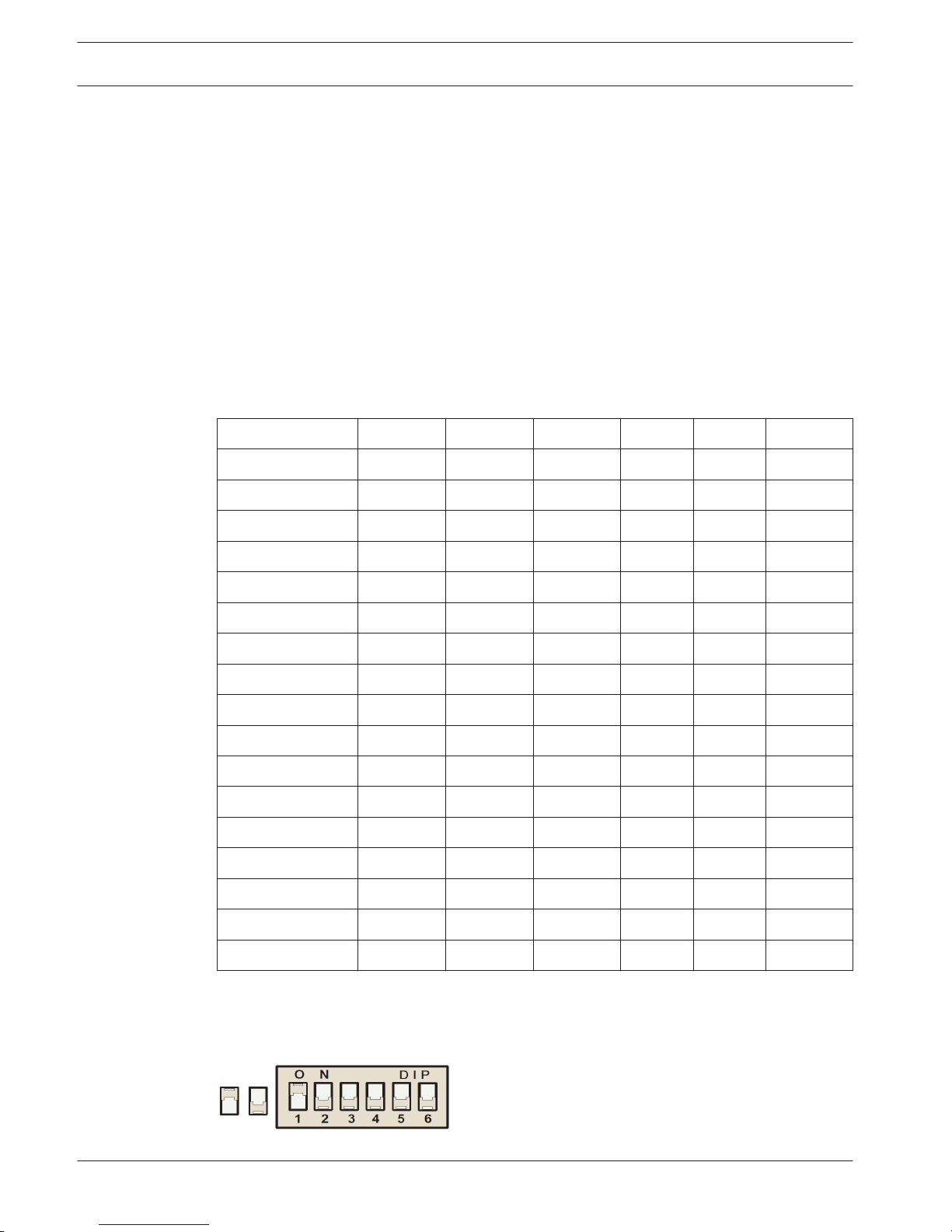
For IUI-AMAX4-TEXT, IUI-AMAX3-LED16, IUI-AMAX3-LED8 keypads, the address of the keypad is
programmed with 6-position DIP switch. The address of each keypad is unique.
DIP Switch S1 S2 S3 S4 S5 S6
Keypad Address 1 2 3 4 5 6
1 On Off Off Off Off Off
2 Off On Off Off Off Off
3 On On Off Off Off Off
4 Off Off On Off Off Off
5** On Off On Off Off Off
6** Off On On Off Off Off
7** On On On Off Off Off
8** Off Off Off On Off Off
9* On Off Off On Off Off
10* Off On Off On Off Off
11* On On Off On Off Off
12* Off Off On On Off Off
13* On Off On On Off Off
14* Off On On On Off Off
15* On On On On Off Off
16* Off Off Off Off On Off
Table 5.2: Keypad Address Settings
* AMAX4000
** AMAX3000/4000
On Off
Figure 5.1: 6-Position DIP Switch
5.2
5.2.1
5.2.2
12 en | Optional Modules and Peripheral Devices
AMAX panel 4000 / AMAX panel 4000
EN
2014.4 | 01 | F.01U.267.112 Installation Guide Bosch Sicherheitssysteme GmbH
Page 13
DIP switches 5 and 6 are not used.
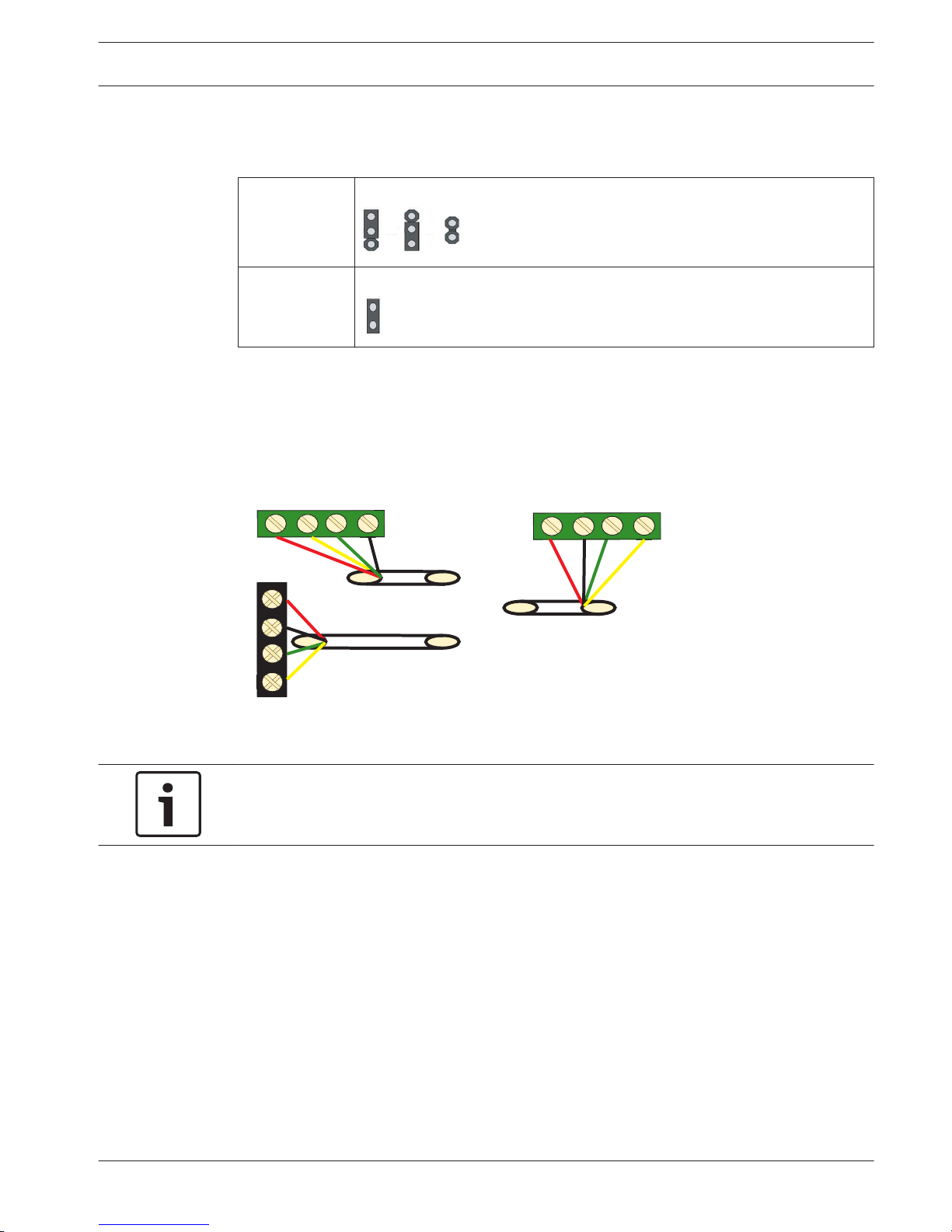
IUI-AMAX-LED8 and IUI-AMAX-LCD8 keypads can be set only to address 1 or address 2 through
the address jumper.
Address 1 Jumper not short-circuited
Address 2 Jumper short-circuited (both metal pins are covered)
Table 5.3: Keypad Jumper Settings
Wiring
Connect the keypad to Bosch Option Bus of AMAX panel according to the following figure. The
last keypad must be placed within a cable distance of 200m.
AMAX 4000
Y
R
Y
G
B
AMAX 2100 / 3000
Keypad
R
B
G
R
B
G
Y
Figure 5.2: Connecting keypad to the AMAX Panel
Notice!
One single Bosch Option Bus is limited up to 8 keypads.
Status Indicator
If all indicators are blinking, then the keypad loses data connection to the AMAX panel.
DX2010
General
The AMAX panel supports DX2010 input expansion modules. Each expansion module supports
up to 8 zone inputs.
See also
– Module Installation, page 23
5.2.3
5.2.4
5.3
5.3.1
AMAX panel 4000 / AMAX panel 4000
EN
Optional Modules and Peripheral Devices | en 13
Bosch Sicherheitssysteme GmbH Installation Guide 2014.4 | 01 | F.01U.267.112
Page 14
Address Setting
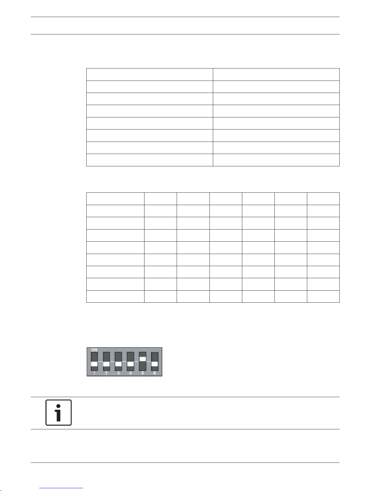
Each DX2010 module connected to the AMAX panel must have its own data bus address.
Data Bus Address Zones
102*** 9 - 16
103** 17 - 24
104** 25 - 32
105* 33 - 40
106* 41 - 48
107* 49 - 56
108* 57 - 64
Table 5.4: DX2010 Address Settings
DIP Switch
S1 S2 S3 S4 S5 S6
Data Bus Address 32 16 8 4 2 1
102*** Off Off Off Off Off On
103** Off Off Off Off On Off
104** Off Off Off Off On On
105* Off Off Off On Off Off
106* Off Off Off On Off On
107* Off Off Off On On Off
108* Off Off Off On On On
Table 5.5: DX2010 DIP Switch Settings
* AMAX 4000
** AMAX 3000 / 4000
*** AMAX 3000
Example : Data Bus Location 103 - DIP Settings
Figure 5.3: DX2010 DIP Switch Settings
Notice!
When data bus address is changed, the module needs to be re-powered to make the new
address effective.
Wiring
Do not use twisted pair or shielded cables to connect DX2010 and the AMAX panel.
5.3.2
5.3.3
14 en | Optional Modules and Peripheral Devices
AMAX panel 4000 / AMAX panel 4000
EN
2014.4 | 01 | F.01U.267.112 Installation Guide Bosch Sicherheitssysteme GmbH
Page 15
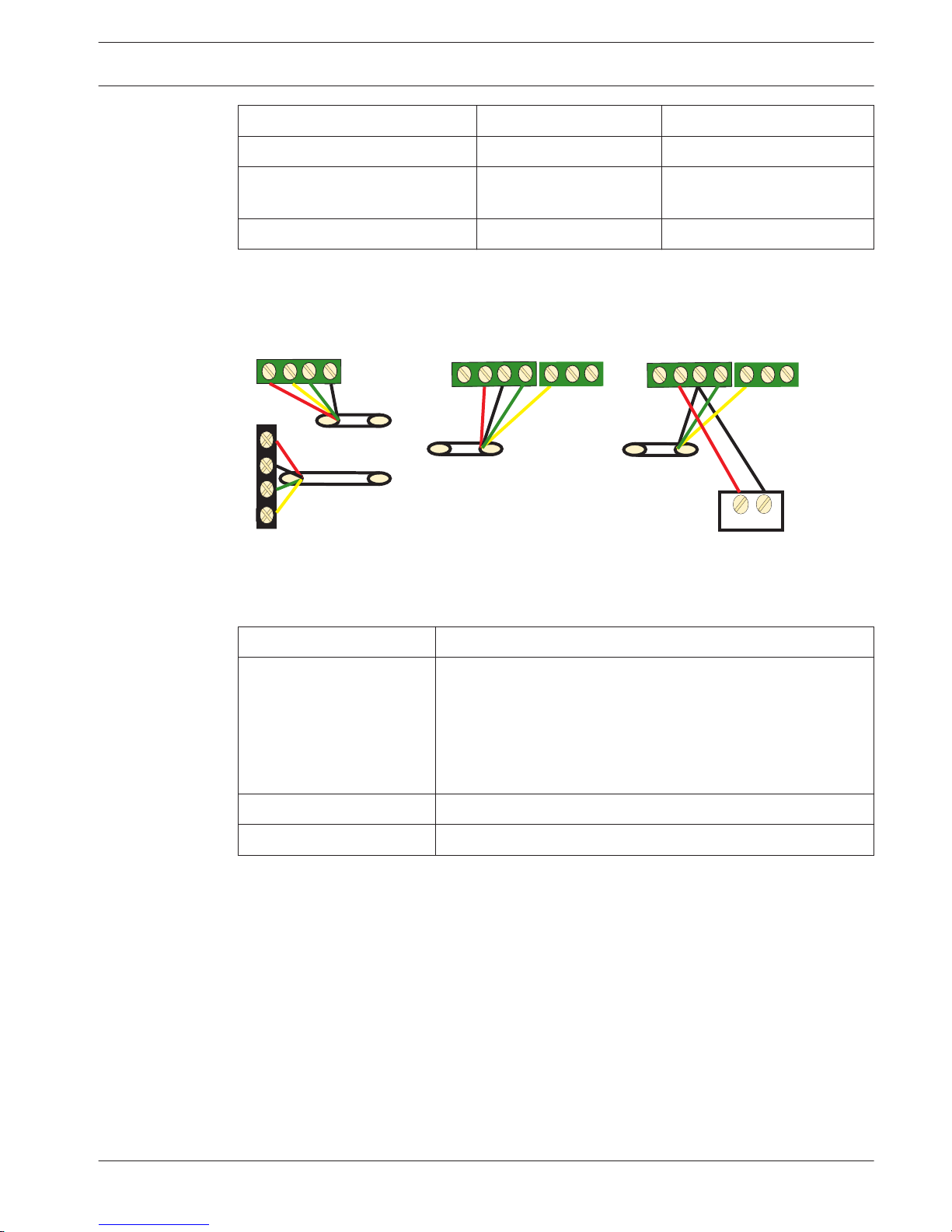
Power Supply Wire diameter of 0.8mm Wire diameter of 1.2mm
AMAX Panel 30m 76m
AMAX Panel (DX2010 Out not
used)
305m 610m
External Power Supply 305m 610m
Table 5.6: Lengths of cable for DX2010
+
12V
AMAX 4000
Y
R
Y
G
B
R
B
G
_
R
B
G
Y
1
COM
TMPR
R
B
G
Y
1
COM
TMPR
AMAX 2100 / 3000
DX2010
DX2010
Figure 5.4: Connecting DX2010 to the AMAX Panel
Status Indicator
LED Condition Denotation
On Trouble Condtion:
– Grounding Conductor is not connected or there is a
communication failure between the module and the AMAX
panel.
– No zones distributed
– Module address setting error
Flash (once per second) Normal Operation
Off Power failure
DX3010
General
The AMAX panel supports DX3010 output expansion modules. Each module supports eight
fully programmable relay outputs. For more information about installation, see DX3010
Installation Guide.
See also
– Module Installation, page 23
Address Setting
Each DX3010 module connected to the AMAX panel must have its own data bus address.
5.3.4
5.4
5.4.1
5.4.2
AMAX panel 4000 / AMAX panel 4000
EN
Optional Modules and Peripheral Devices | en 15
Bosch Sicherheitssysteme GmbH Installation Guide 2014.4 | 01 | F.01U.267.112
Page 16
Data Bus Address Outputs
150 5-12
151* 13-20
Table 5.7: DX3010 Address Settings
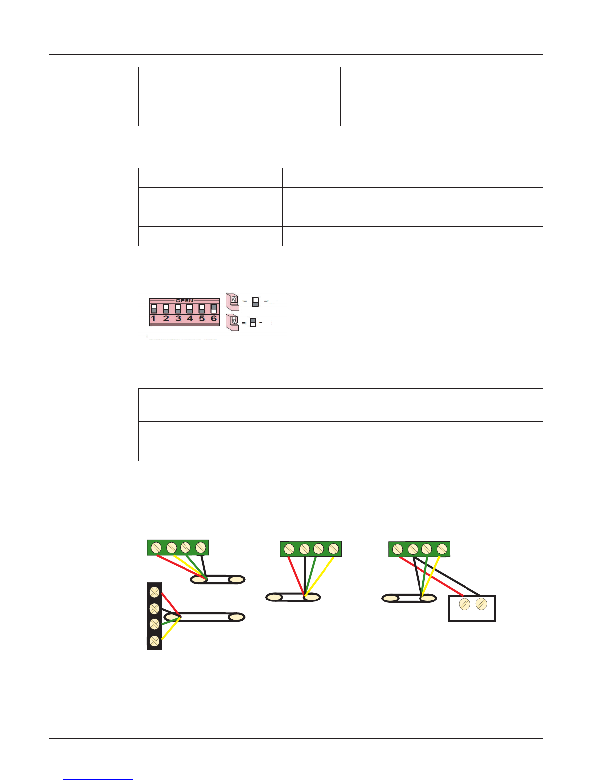
DIP Switch S1 S2 S3 S4 S5 S6
Data Bus Address 1 2 4 8 16 Mode
150 On On On On On Off
151* Off On On On On Off
Table 5.8: DX3010 DIP Switch Settings
* AMAX 3000 / 4000
Example : Data Bus Location 150 - DIP Settings
On
Off
Figure 5.5: DX3010 DIP Switch Settings
Wiring
Power Supply Wire diameter of
0.8mm
Wire diameter of 1.2mm
AMAX Panel 12.2m 24.4m
External Power Supply 305m 610m
Table 5.9: Lengths of cable for DX3010
+
12V
AMAX 4000
Y
R
Y
G
B
AMAX 2100 / 3000
DX3010
R
B
G
DX3010
R
B
G
Y
R
B
G
Y
_
Figure 5.6: Connecting DX3010 to the AMAX Panel
Status Indicator
None.
5.4.3
5.4.4
16 en | Optional Modules and Peripheral Devices
AMAX panel 4000 / AMAX panel 4000
EN
2014.4 | 01 | F.01U.267.112 Installation Guide Bosch Sicherheitssysteme GmbH
Page 17
B426
General
AMAX panel supports up to two communication modules.
– ITS-DX4020-G and B426 or B426 and B426
The B426 Ethernet communication module supports monitored two-way IP communication via
Ethernet to perform alarm transmission, remote programming, and control of the AMAX panel.
Before installing B426, all power supplies (AC power supply and backup battery power
supply) of the AMAX panel should be disconnected. Use the standard three-hole installation
mode to install B426 in the enclosure of the AMAX panel or in another enclosure. To
reconfigure the module or connected to the alarm control panel with RPS, the network or
direct connection must be used to access its built-in Web server.
For more information about installation and configuration, see B426 Installation and Operating
Guide.
Address Setting
Turn the rotary switch to 6, i.e., set the address to 134 when the first B426 is used. Turn the
rotary switch to 9, i.e., set the address to 250 when the second B426 is used.
Wiring
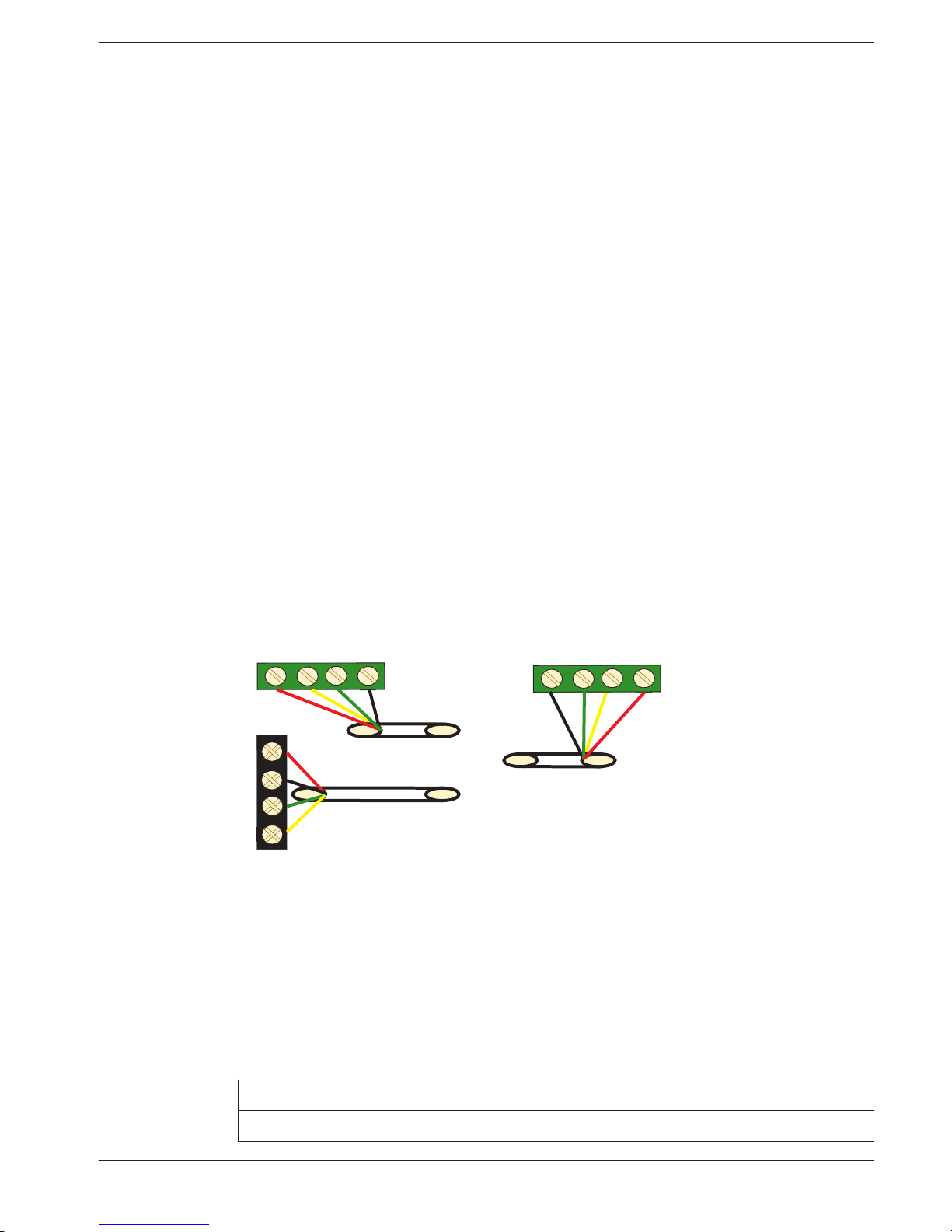
Connect B426 to Bosch option Bus 1 or 2. The cable may not exceed 150 meters.
AMAX 4000
Y
R
Y
G
B
AMAX 2100 / 3000
B426
R
B
G
R
B
G
Y
Figure 5.7: Connecting B426 to the AMAX Panel
Status Indicator
B426 provides the following on-board LED indicators to help in troubleshooting.
– Blue system status indicator.
– Green data bus indicator.
– Green Ethernet link indicator.
LED Condition Denotation
On Trouble Condition
5.5
5.5.1
5.5.2
5.5.3
5.5.4
AMAX panel 4000 / AMAX panel 4000
EN
Optional Modules and Peripheral Devices | en 17
Bosch Sicherheitssysteme GmbH Installation Guide 2014.4 | 01 | F.01U.267.112
Page 18
Flash (stable flash) Normal Operation
Flash (3 flashes) Normal power supply, without communication
Off Power failure or other failure conditions
Table 5.10: B426 System Status Indicator
For more information about indicators, see B426, page 17.
DX4020-G
General
The Conettix ITS-DX4020-G GPRS communication module allows IP communication via
commercial GPRS network. Transmission of alarm information via GPRS is the default for ITSDX4020-G. SMS or USB mode can be chosen for configuration. Remote programming and
control of the AMAX panel is supported.
Installation
1. Before installing ITS-DX4020-G, all power supplies of the AMAX panel should be
disconnected.
2. Insert SIM card.
3. Use the standard three-hole installation mode to install the ITS-DX4020-G in the enclosure
of the AMAX panel or another enclosure.
4. Connect the magnetic antenna to ITS-DX4020-G.
Address Setting
Set bus address to 134.
See also
– DX4020-G, page 18
Wiring
The connection of ITS-DX4020-G and the AMAX panel is divided into two modes: GPRS and
GSM.
AMAX 4000
Y
R
Y
G
B
AMAX 2100 / 3000
R
B
G
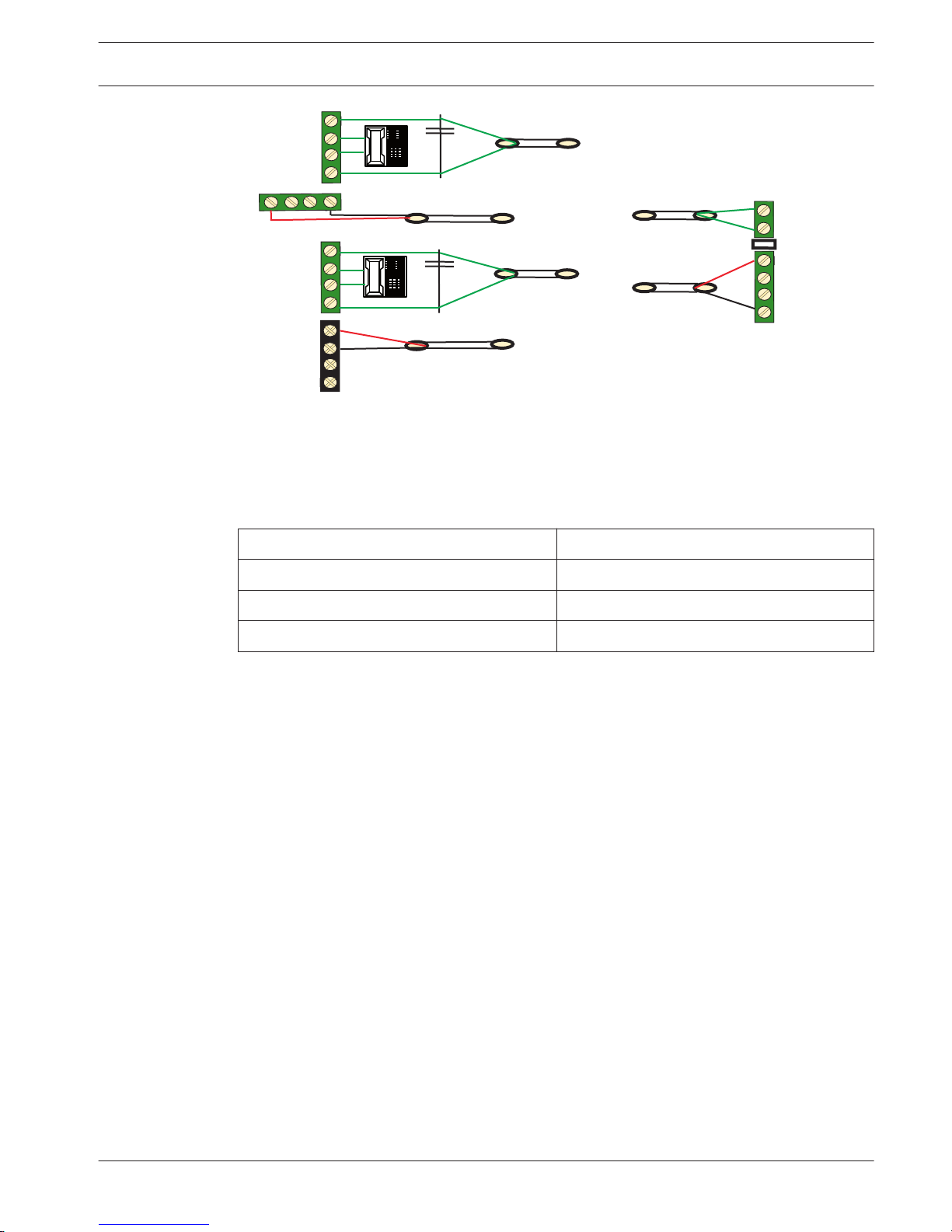
DX4020G
R
B
G
Y
Figure 5.8: GPRS Mode in Support of IP
5.6
5.6.1
5.6.2
5.6.3
18 en | Optional Modules and Peripheral Devices
AMAX panel 4000 / AMAX panel 4000
EN
2014.4 | 01 | F.01U.267.112 Installation Guide Bosch Sicherheitssysteme GmbH
Page 19
DX4020G
BUS
AMAX 4000
R
Y
G
B
RING
TIP
RH
TH
R
B
G
Y
PNL
PSTN
TIP
TIP
1RING
1RING
R
Y
G
B
AMAX 2100 / 3000
Figure 5.9: GSM Mode in Support of PSTN (Contact ID)
Status Indicator
The AMAX panel tests the communication normally with the module. In case of communication
failure, a fault report including the module address is sent.
LED Condition Denotation
On Normal Condition
Flash Trouble Condition
Off Power Failure
Table 5.11: DX4020-G System Status Indicator
For more information on indicators, configuration and other topics related to ITS-DX4020-G,
see Installation and Operation Guide.
RF 3227E RF
General
The RF3227E RF receiver allows the use of wireless devices using the AMAX panel 3000 /
4000.
Installation
Whenever possible, the receiver should be mounted in a central location with regard to all
wireless sensors. The receiver should be mounted vertically, with at least 25 cm clearance
above it for the antennas. Avoid mounting the receiver in areas with significant metal or
electrical wiring such as furnace, or utility rooms. If this is unavoidable, mount the receiver
with the antennas extending above any metal surface. Avoid mounting the receiver in areas
where it may be exposed to moisture. Reception distances are generally improved with higher
mounting locations and with no metal objects near the antennas.
Address Setting
Set receiver address to #1. The AMAX panel supports only receiver 1, not receiver 2.
5.6.4
5.7
5.7.1
5.7.2
AMAX panel 4000 / AMAX panel 4000
EN
Optional Modules and Peripheral Devices | en 19
Bosch Sicherheitssysteme GmbH Installation Guide 2014.4 | 01 | F.01U.267.112
Page 20
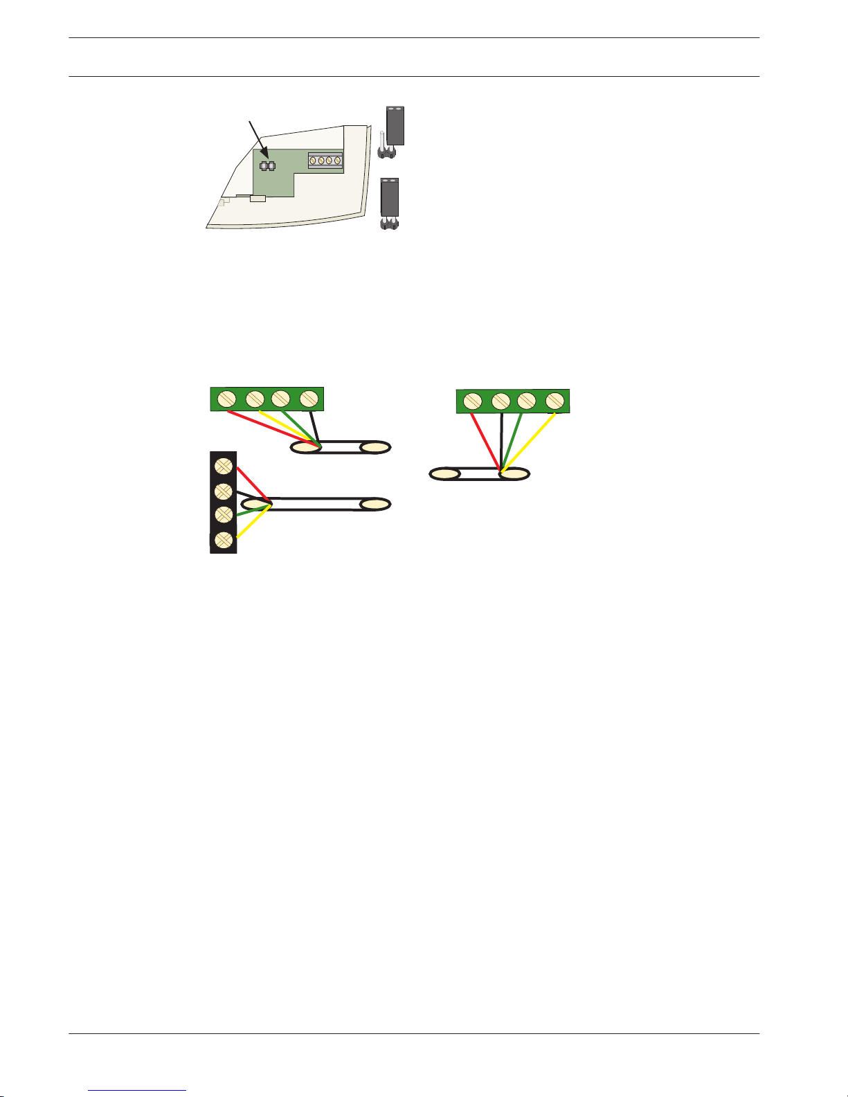
No Jumper = Receiver # 1 (Default)
Jumper = Receiver # 2
Address Jumper
Jumper left on pin for storage only.
R
B
G
Y
ADDR
Figure 5.10: Address
Wiring
Connect the RF3227E receiver to Bosch option Bus. The cable must not exceed 300 m. Adding
additional devices to the bus might reduce the maximum distance. Shielded cable is not
required. Do not use twisted pair wires.
AMAX 4000
Y
R
Y
G
B
AMAX 2100 / 3000
RF3227E
R
B
G
R
B
G
Y
Figure 5.11: Connecting RF3227E
5.7.3
20 en | Optional Modules and Peripheral Devices
AMAX panel 4000 / AMAX panel 4000
EN
2014.4 | 01 | F.01U.267.112 Installation Guide Bosch Sicherheitssysteme GmbH
Page 21
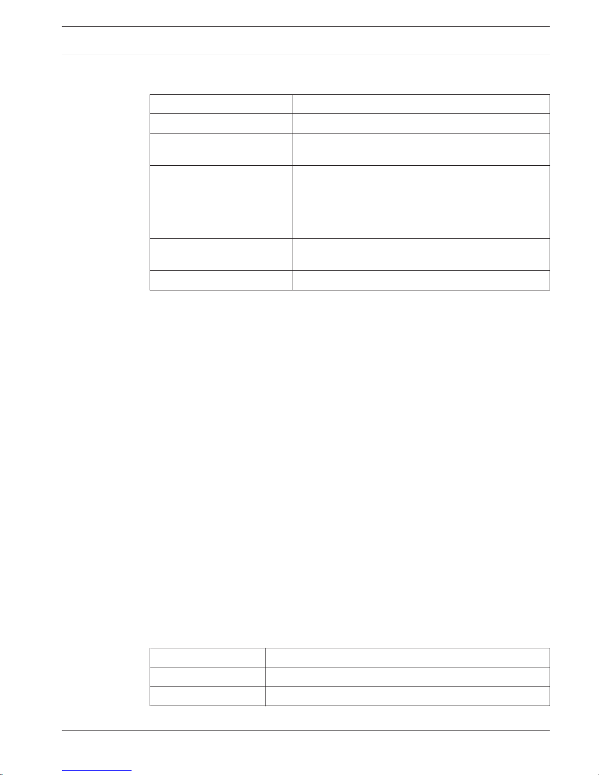
Status Indicator
LED Condition Denotation
On Normal Operation
Momentarily on The receiver has acknowledged receiving a message from a
compatible transmitter.
Flashes rapidly for less than one
minute
The receiver is being programmed with zone and
transmitter IDs from the AMAX panel. This condition occurs
during system initialization (power up), or when new zone
information is programmed into the system. The rapid
flashing lasts for less than one minute.
Flashes rapidly for more than
one minute
The receiver has failed power-up self tests. Replace the
receiver.
Off Power failure or wiring failure
Table 5.12: RF 3227E RF System Status Indicator
RF Radion Receiver
General
RADION receiver OP is a wireless receiver that connects the RADION Wireless System
components to the AMAX panel 3000 / 4000. Features include:
– Cover and wall tamper protection
– RFID and configuration data are contained in persistent memory
– Detection and reporting of radio frequency interference
– Supports two types of device enrollment
Installation
Use the provided anchors and screws to mount the receiver in locations accessible for future
maintenance. Mount the receiver onto a wall.
For best reception, place the receiver in a central location among the transmitters. In
situations where there is a large distance between the transmitter and receiver, it might be
necessary to install receivers for optimum results.
Address Setting
Set rotary switch to value 1. The AMAX panel supports one receiver only.
Wiring
Connect the RADION receiver to bosch option bus. The cable distance to the AMAX panel may
not exceed 300 meters.
Status Indicator
LED Condition Denotation
On Normal operation
Off Power failure or wiring failure
5.7.4
5.8
5.8.1
5.8.2
5.8.3
5.8.4
AMAX panel 4000 / AMAX panel 4000
EN
Optional Modules and Peripheral Devices | en 21
Bosch Sicherheitssysteme GmbH Installation Guide 2014.4 | 01 | F.01U.267.112
Page 22
Continuous Flash: 1 sec
On, 1 sec Off
Receiver is being programmed with the zone and transmitter IDs
from the AMAX panel.
Turns Off momentarily Receiver has obtained a valid transmission from a RADION
transmitter.
Continuous Flash: A 3pulse signal, followed by
a short delay at the end
of the 3rd pulse
Communication error and / or a self-test failure.
Causes:
– A communication failure between the AMAX panel and the
receiver or
– An invalid address switch setting.
Table 5.13: RFRC-OPT Radion Receiver System Status Indicator
22 en | Optional Modules and Peripheral Devices
AMAX panel 4000 / AMAX panel 4000
EN
2014.4 | 01 | F.01U.267.112 Installation Guide Bosch Sicherheitssysteme GmbH
Page 23
Installation
This chapter specifies installation and system power up of the AMAX panel.
During installation and wiring, the AMAX panel power source must be switched-off to prevent
equipment damage.
– To switch off the power source, an easy accessible circuit breaker must be available
– The system / product must be connected to a socket-outlet with a protective earthing
contact
The User has to disconnect all Telecommunication Network Connectors before unplugging the
power adaptor.
Module Installation
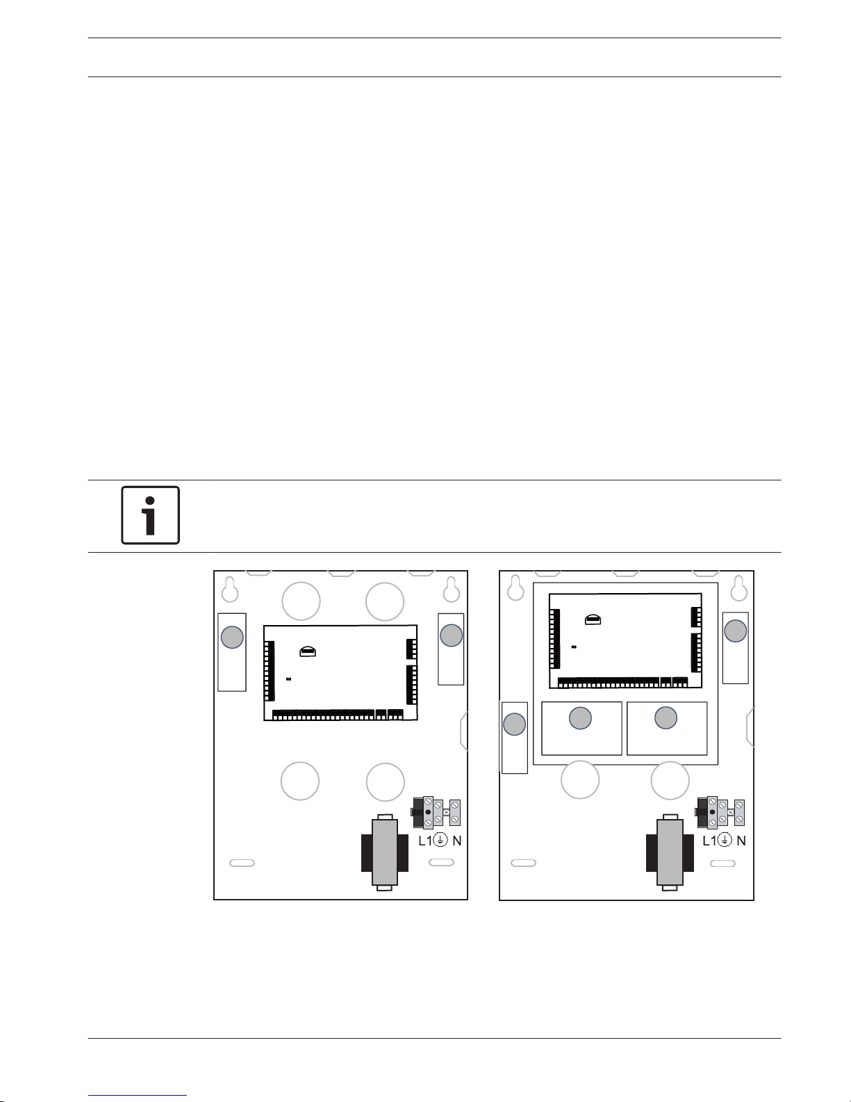
The enclosure contains only PCBs and transformers of the fixed AMAX panel, not other
hardware for installation.
1. Open the knockout holes for wiring in the module.
2. Position two upper mounting holes on the installation wall with the module.
3. Pre-install screws on the mounting holes (provided by the installer).
4. Mount the screws on the module.
5. Fasten the screws.
6. Fix the two lower mounting holes with screws.
Notice!
Please choose appropriate positioning screw kit when you have to install in a non-load
bearing wall.
E N √ E N √
2
Enclosure - Standard
Enclosure with mounting plate
GND
-
+
AC
AC
L2
COM
COM
COM
L1a
L3
L4
L5
L6
L7
L8
L9
COM
COM
COM
COM
L10
L11
L12
L13
L14
L15
L16
P0+4
R
B
G
Y
AUX1
-
AUX2
-
AUX1
+12V
Y
G
B
R
RINGRHTHTIP
L1b
P0+3
P0+
P0-2
P0-1
AUX2
+12V
♥
GND
-
+
AC
AC
L2 COM
COM
COM
L1a
L3
L4
L5
L6
L7
L8
L9
COM
COM
COM
COM
L10
L11
L12
L13
L14
L15
L16
P0+4
R
B
G
Y
AUX
1
-
AUX
2
-
AUX
1
+12V
Y
G
B
R
RINGRH
TH
TIP
L1b
P0+3
P0+
P0-2
P0-1
AUX
2
+12V
♥
1
2
1
3
4
Figure 6.1: Enclosure / with mounting plate
6
6.1
AMAX panel 4000 / AMAX panel 4000
EN
Installation | en 23
Bosch Sicherheitssysteme GmbH Installation Guide 2014.4 | 01 | F.01U.267.112
Page 24
GND
-
+
AC
L8
12V
R
B
G
Y
1RING
TIP
P0+
P0-2
P0-1
TIP
COM
L7
L6
COM
L5
COM
L4
L3
L2
COM
L1
AC
COM
B
A
PWR
1RING
♥
EN √
1
Figure 6.2: Enclosure / with mounting plate
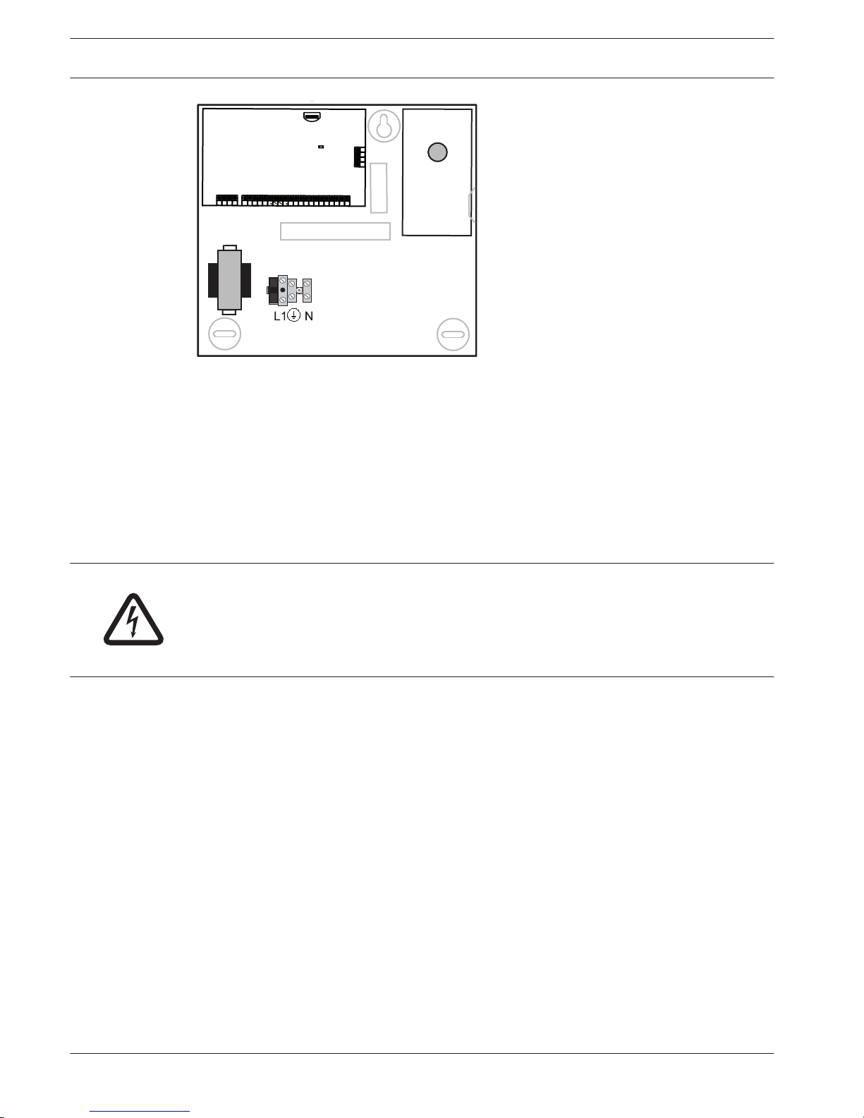
Expansion modules can be placed in enclosure of the AMAX panel. Several places are
available. Figure 6.1. shows standard enclosure installation and enclosure installation with
mounting plate.
Battery Installation
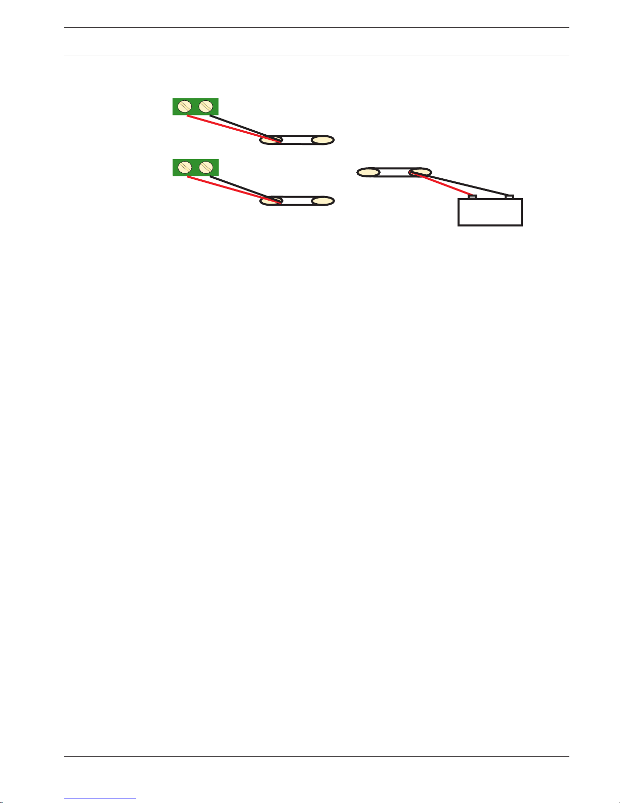
The AMAX Panel supports one sealed lead-acid rechargeable battery. After the battery is fully
charged, it can be used as backup power supply to support the system.
Please refer to , page 151
Danger!
Special care is required in connecting the positive (red) wire and the “BATT +” port of the
AMAX panel. If you short-circuit the “BATT +” port of the AMAX panel or the enclosure, an
electric arc will occur. To remove the battery from the AMAX panel, the positive wire of the
battery should be disconnected first.
1. Place the battery on the bottom of the enclosure.
2. Position the red and black wires.
3. Connect one end of the black wire to the "BATT -" port of the AMAX panel, and the other
end to the negative (-) pole of the battery.
4. Connect one end of the red wire to the "BATT +" port of the AMAX panel, the other end to
the positive (+) pole of the battery.
Once the installation is complete, the AMAX panel will begin to charge the battery.
6.2
24 en | Installation
AMAX panel 4000 / AMAX panel 4000
EN
2014.4 | 01 | F.01U.267.112 Installation Guide Bosch Sicherheitssysteme GmbH
Page 25
AMAX 2100 / 3000
AMAX 4000
+
_
BATTERY
+
_
BATT
+
Battery
_
Figure 6.3: Connection of Battery
System Power Up
After the AMAX panel is powered up, set the date and time. Otherwise, the system prompts as
fault.
After the AMAX panel is powered up or reset, it resets to previous arming / disarming status.
To reduce false alarms caused by system power-up (or by power supply restoration after both
mains supply and AUX power supply fail), the AMAX panel is designed to not perform zone test
within one minute after power-up.
System Status Indicator
The AMAX panel indicates the system status by using the LED status indicator on the system
main board.
Slow flash of red on status indicator (repeating on and off with an interval of 1 second)
indicates normal system operation.
6.3
6.4
AMAX panel 4000 / AMAX panel 4000
EN
Installation | en 25
Bosch Sicherheitssysteme GmbH Installation Guide 2014.4 | 01 | F.01U.267.112
Page 26
Prerequisites for Certification conform Installation
EN 50131-3 Grade 2, Environmental Class 2 - AMAX 2100 / 3000 / 4000
The P anel complies with the Following Standards:
EN 50131- 3
EN 50131- 6
EN 50136 - 2- 1
EN 50136 - 2- 3
Certification Body
VDS Schadenverhütung
Amsterdamer Str.172
50735 Köln
www.vds.de
– The system / product must be placed inside the monitored area on a stable surface
– Keypads must be mounted to the inner side of the monitored area
– Once the system is tested and ready to use, enclosure door and accessory enclosures
must be secured with the provided screws
– To realize EN conform Alarm Indication and Transmission, one of the following devices
must be used
– Two supervised Warning devices (PO-1 PO-2 & PO+) and one ATS 2 Communicator
(onboard Dialer, B426, D4020 or DX4020G)
– One self powered Warning Device and one ATS 2 Communicator (onboard Dialer,
B426, D4020 or DX4020G)
– Two Communicators, one ATS 2 (onboard Dialer, B426, D4020 or DX4020G) and one
ATS 1 (onboard Dialer, B426, D4020 or DX4020G)
– One ATS 3 Communicator (DX4020 or B426)
All Communicators must be connected to a central monitoring station.
Only the onboard Dialer and the Option Bus Communicators can be used for EN Alarm
Transmission.
– one 12V / 7AH or one 12V / 18Ah Battery must be connected to the System
– maximum current for all components with a 7Ah Battery = 550mA
– maximum current for all components with a 18Ah Battery = 1500mA (standby 12h,
recharge battery 80% in 72h) (PCB =l 00mA, IUI-AMAX Keypads = 31mA, DX2010 = 35mA,
DX3010 = 10mA, B426 = 100mA, DX4020G = 65mA, RF3227E = 30mA, RFRC-OPT = 30mA)
– To realize EN conform Arming procedure, an indication of arm / disarm status must be
accessible from outside the monitored area (this indication can be time limited)
– To realize EN conform Access to the Monitored Area, one of the following methods must
be used
– Opening a door (to the entry / exit route) must start the entry procedure
– Indication of arm / disarm Status
6.5
6.5.1
26 en | Installation
AMAX panel 4000 / AMAX panel 4000
EN
2014.4 | 01 | F.01U.267.112 Installation Guide Bosch Sicherheitssysteme GmbH
Page 27

– Access to the monitored area (doors not starting entry procedure) is prevented (e.g.
door strike, mechanically)
– The Enclosure lock can only be used in non EN setup
– Telephone arming can only be used in non EN setup
– Accessory Modules, except input module (DX2010) can be used only inside the enclosure
(on the adapter plate)
– When input module (DX2010) is used in the external enclosure (AE20), the tamper skirt
must be installed on the PCB of input module (DX2010)
– The panel must be programmed with the EN settings indicated on the programming sheet
– When the panel is set without EN parameters, the EN Indication (on Label) must be
removed
– Maximum of 10 Devices shall be connected to one Zone Input (Panel, Keypad, Input
Module, RFUN,…)
AMAX panel 4000 / AMAX panel 4000
EN
Installation | en 27
Bosch Sicherheitssysteme GmbH Installation Guide 2014.4 | 01 | F.01U.267.112
Page 28
NFA2P AFNOR / CNPP - AMAX 4000
Certification Body
:
AFNOR Certification
11, rue Francis de Pressensé
93571 LA PLAINE Saint Denis Cedex
Tel: + 33 (0)1 41 62 80 00
Fax: + 33 (0)1 49 17 90 00
Web sites:
www.afnor.org
and www.marque-nf.com
Email: [email protected]
The Panel complies with the Following Standards:
RTC 50131-3 NF3248H58-2011 V1
RTC 50131-6 NF3248H58-2011 V1
Reference:
NF324 H58 2.5 Option 3: Grade 2 (European EN sta ndards) + RTC
Certification Body:
CNPP Cert.
Route de la Chapelle Réanville
CS 22265
27950 SAINT MARCEL
Tel: (33) 2 32 53 63 63
Fax: (33) 2 32 53 64 46
Website:
www.cnpp.com
Email:
Prerequisites for an NFa2p conform Installation
- When aNFa2p conform instalation is made, the environmental class of the Panel is "1”
Certification Number: 1223400001A0
INCERT - AMAX 4000
6.5.2
6.5.3
28 en | Installation
AMAX panel 4000 / AMAX panel 4000
EN
2014.4 | 01 | F.01U.267.112 Installation Guide Bosch Sicherheitssysteme GmbH
Page 29
SFF – AMAX 2100 / 3000 / 4000
Certification Body
SSF Stöldskyddsföreningen
Amsterdamer Str.172
50735 Köln
www.vds.de
VDS Schadenverhütung
Tegeluddsvägen 100
115 87 Stockholm
http://www.stoldskyddsfpreningen.se
The P anel complies with the Following Standards:
SSF 1014 Edition 4 Alarm class 1
6.5.4
AMAX panel 4000 / AMAX panel 4000
EN
Installation | en 29
Bosch Sicherheitssysteme GmbH Installation Guide 2014.4 | 01 | F.01U.267.112
Page 30
Settings
This chapter specifies the properties and the behavior of the AMAX panel.
Communication and Reporting
This section outlines the programming information required for the AMAX panel when
communicating with a base station receiver. These parameters specify the telephone
numbers/IP address to be called, transmission formats, and internet communication options.
Receivers
Receiver Telephone number / IP Address and Port
The AMAX panel can report event information from four on-board dialers. The dialers report to
Receiver 1 to Receiver 4 by programming. You can program each dialer with 4 separate
telephone numbers/IP addresses and ports, reporting format type and subscriber ID number,
and internet communication options if necessary.
Example
You can set up Dialer 1 to report to receiver 1 in Bosch Network (Conettix) Format and set up
Dialer 2, Dialer 3, and Dialer 4 to report to a receiver of a central monitoring station in Contact
ID Format only, if Dialer 1 is unsuccessful.
To program a telephone number:
Each address in the telephone numbers stores one digit of the telephone number.
Insert a 15 at the end of a telephone number to indicate to the dialer that the end of the
telephone number is reached. The dialing sequence is terminated when a 15 appears.
Example
To program the telephone number 9672 1055 as the Telephone Number for Receiver 1,
program the following sequence into Address 000 - 016:
[9 6 7 2 1 0 5 5 15 x x x x x x x x] x stands for any digit. To enter a 4-sec pause in the dialing
sequence, program a 13. A pause might be necessary when the dialer communicates through
an old (slower) telephone exchange or when a PABX system is in place.
Example
To program the number 02 pause 9672 1055, enter:
[0 2 13 9 6 7 2 1 0 5 5 15 x x x x x].
The following table shows how to program the numbers, keys, and functions for a telephone
number.
Digit Required
Number to Program Digit Required Number to Program
0 0 8 8
1 1 9 9
2 2 * 11
3 3 # 12
4 4 4 sec pause 13
5 5 Terminal 15
6 6
7 7
Table 7.1: Dialing Digits
7
7.1
7.1.1
30 en | Settings
AMAX panel 4000 / AMAX panel 4000
EN
2014.4 | 01 | F.01U.267.112 Installation Guide Bosch Sicherheitssysteme GmbH
Page 31
To program the IP Address and port:
Use no punctuation in IP address. If any unit of IP address is less than 3 digits, use 0 to fulfill
the data in the higher bits. The remaining 5 digits will program the port. Port number ranges
from 0-65535. If port number is less than 5 digits, use 0 to fulfill the data.
Example
To program the IP Address 10.16.1.222:80 as the IP Address of Receiver 1, enter the following
sequence into Address 000 - 016:
[0 1 0 0 1 6 0 0 1 2 2 2 0 0 0 8 0]
Notice!
Programming option anti-replay, acknowledge wait time, and pulse interval time are only used
in Conettix IP.
Telephone number for Receiver 1 - 4/IP Address and Port
When the corresponding data format for above programming address is a network
communication format, it is explained as an IP Address, and Port. For a non network format, it
is explained as telephone number.
AMAX panel contacts the telephone number / IP Address of the central monitoring station in
order to transmit a report. If the contact is successful, the relevant information is transmitted,
and the communicator returns to Standby Mode.
Contact your monitoring station for the correct telephone number / IP Address before you
program these addresses.
Receiver Subscriber ID Number
Receiver 1 - 4 Subscriber ID Number
The Subscriber ID Number is transmitted to identify the calling AMAX panel. Digits from 0 to 9
and letters from B to F are only valid. Enter the Subscriber ID Number in the six addresses
provided for each destination. If a Subscriber ID Number is less than 6 digits, use 0 to full fill
the data in the higher bits.
Example
Program Subscriber ID Number as 4729 in six addresses: [0 0 4 7 2 9]
Receiver Transmission Format
Transmission Format
Receiver 1 - 4 Transmission Format
You can select the transmission format with Address options to specify how to transmit the
information to the base station receiver. If Contact ID or SIA format is selected, the
information is transmitted by telephone line; if Bosch Network is selected, then it is
connected with B426 / DX4020 or ITS-DX4020G GPRS. Transmission format is defaulted as
Contact ID.
Transmission Formats (Contact ID, SIA, Conettix IP)
The AMAX panel 4000 provides three kinds of transmission formats, Contact ID, SIA, and
Conettix IP format for its dialing and communication features. Program the transmission
format for Receiver 1, 2, 3, and 4 separately in Address 023, Address 053, Address 083, and
Address 113 (refer to Transmission Format). The AMAX panel is set at the factory to report in
the Contact ID Format.
AMAX panel 4000 / AMAX panel 4000
EN
Settings | en 31
Bosch Sicherheitssysteme GmbH Installation Guide 2014.4 | 01 | F.01U.267.112
Page 32
Contact ID Format
Contact ID Format can identify hundreds of zones by their unique codes. This format provides
a single-digit Event Qualifier and a three-digit Event Code that quickly identifies the reported
condition.
In general, Contact ID Format is very simple because most of the Event Codes and Point ID
Codes are predefined. The central monitoring station software usually can identify an alarmed
zone by its Point ID Code and usually pays little attention to the Event Code.
– Contact ID Message Format
ACCT MT Q EEE GG CCC S
ACCT = Subscriber ID
MT = Message type, H
Q = Event Qualifier
1= New event or Opening
3= New restore or Closing
6= Previously reported off-normal event
EEE = Event Code
GG = Group Number (always 0)
CCC = Zone/ Contact ID, 000 is for no zone / ID message
S = Checksum digit
Note: Any 0 values must be sent as an 0x0A.
Contact ID Report Data.
SIA Format
AMAX panel supports SIA Format. SIA allows transmitting System ID, event code, zone ID, area
ID, event time, and also event text.
Conettix IP Format
AMAX panel supports Conettix IP. AMAX panel with DX4020G and B426 are able to connect to
Bosch Receivers 6600/6100 using Conettix IP Format.
Event Description
CID SIA ALL
EventKPRecall
Dialer
EventENEvent
SYSTEM RESET √ √
BURG ALARM 1130 BA √ √ √ √
BURG ALARM RESTORE 3130 BR √
BURG 24-HOUR 1133 BA √ √ √ √
BURG 24-HOUR RESTORE 3133 BH √
SENSOR FAULT 1380 BT √
SENSOR FAULT RESTORE 3380 BJ √
SENSOR BYPASS 1570 BB √ √
SENSOR BYPASS RESTORE 3570 BU √
SENSOR TAMPER 1144 TT √ √ √
SENSOR TAMPER RESTORE 3144 TJ √
ARM AWAY 3401 CL √ √ √
DISARM AWAY 1401 OP √ √ √
32 en | Settings
AMAX panel 4000 / AMAX panel 4000
EN
2014.4 | 01 | F.01U.267.112 Installation Guide Bosch Sicherheitssysteme GmbH
Page 33

Event Description CID SIA ALL
EventKPRecall
Dialer
EventENEvent
ARM STAY 3441 CL √ √ √
DISARM STAY 1441 OP √ √ √
KEYPAD PANIC 1120 PA √ √
KEYPAD FIRE 1110 FA √ √
KEYPAD EMERGENCY 1100 QA √ √
DURESS 1121 HA √ √
KEYPAD TOOMUCH RETRY 1421 JA √ √
BATTERY LOW 1309 YT √ √
BATTERY RESTORE 3309 YR √ √
AC FAIL 1301 AT √ √
AC RESTORE 3301 AR √ √
AUX POWER 1300 IA √
AUX POWER RESTORE 3300 IR √
COMM TEST 1602 RP
CONFIG CHANGED 1306 YG √ √
COMM FAIL 1350 YC √ √ √
COMM RESTORE 3350 YK √ √
EXTERNAL MODULE FAULT 1333 EM √ √
EXTERNAL MODULE RESTORE 3333 EN √
EXTERNAL MODULE TAMPER 1341 ES √ √
EXTERNAL MODULE TAMPER RESTORE 3341 EJ √
DATE TIME SET 1625 JT √ √
USER CODE CHANGE JV √ √
ENTER PROGRAM MODE LB √
EXIT PROGRAM MODE LX √
PHONE LINE FAIL 1351 LT √ √ √
PHONE LINE RESTORE 3351 LR √ √
PANIC 24-HOUR 1120 PA √ √ √
PANIC 24-HOUR RESTORE 3120 PH √
FIRE 24-HOUR 1110 FA √ √ √
FIRE 24-HOUR RESTORE 3110 FH √
OUTPUT FAULT 1320 YA √ √
AMAX panel 4000 / AMAX panel 4000
EN
Settings | en 33
Bosch Sicherheitssysteme GmbH Installation Guide 2014.4 | 01 | F.01U.267.112
Page 34
Event Description CID SIA ALL
EventKPRecall
Dialer
EventENEvent
OUTPUT RESTORE 3320 YA √
DAYLIGHT SAVING TIME +1h 1625 JT √ √
DAYLIGHT SAVING TIME -1h 1625 JT √ √
FAULT OVERRIDE √ √
PANEL ACCESS 1422 JP √ √
SOFTWARE UPDATE YZ √ √
REMOTELINK SUCCESS 1412 RB √
CLOCK FAIL 1626
TAMPERZONE TAMPER 1137 TA √ √ √
TAMPERZONE TAMPER RESTORE 3137 TH √
ZONE EXT FAULT 1150 UA √ √ √
ZONE EXT FAULT RESTORE 3150 UR √
DELAY EXIT 1134 BA √ √
DELAY EXIT RESTORE 3134 BR √
BURG ALARM VERIFIED 1139 BV √ √ √ √
BURG ALARM UNVERIFIED 1130 BG √ √
IP MODULE FAULT 1333 EM √ √ √
IP MODULE RESTORE 3333 EN √ √
PRINTER MISSING 1336 VZ √
PRINTER MISSING RESTORE 3336 VY √
PRINTER ERROR 1335 VT √
PRINTER ERROR RESTORE 3335 VR √
PRINTER MODULE MISSING 1333 EM √
PRINTER MODULE MISSING RESTORE 3333 EN √
RF RECEIVER MISSING 1333 EM √
RF RECEIVER MISSING RESTORE 3333 EN √
RF RECEIVER TAMPER 1341 ES √
RF RECEIVER TAMPER RESTORE 3341 EJ √
RF RECEIVER FAULT 1333 ET √
RF RECEIVER FAULT RESTORE 3333 ER √
RF RECEIVER JAM 1344 XQ √
RF RECEIVER JAM RESTORE 3344 XH √
34 en | Settings
AMAX panel 4000 / AMAX panel 4000
EN
2014.4 | 01 | F.01U.267.112 Installation Guide Bosch Sicherheitssysteme GmbH
Page 35

Event Description CID SIA ALL
EventKPRecall
Dialer
EventENEvent
RF RECEIVER CONFIGURATION CONFLICT √
RF RECEIVER CONFIGURATION CONFLICT
RESTORE
√
RF POINT MISSING 1381 UY √
RF POINT MISSING RESTORE 3381 UJ √
RF POINT BATTERY FAULT 1384 XT √
RF POINT BATTERY FAULT RESTORE 3384 XR √
RF POINT FAULT 1380 BT √
RF POINT FAULT RESTORE 3380 BJ √
RF REPEATER MISSING 1382 UY √
RF REPEATER MISSING RESTORE 3382 UJ √
RF REPEATER BATTERY FAULT 1384 XT √
RF REPEATER BATTERY FAULT RESTORE 3384 XR √
RF REPEATER TAMPER 1383 XS √
RF REPEATER TAMPER RESTORE 3383 XJ √
RF REPEATER AC FAULT 1334 YP √
RF REPEATER AC FAULT RESTORE 3334 YR √
RF KEYFOB BATTERY FAULT 1384 XT √
RF KEYFOB BATTERY FAULT RESTORE 3384 XR √
RF KEYFOB PANIC ALARM 1120 PA √
RF KEYFOB SILENT ALARM 1122 HA √
RF CHANGE KEYFOB √
FIRE UNVERIFIED 1378 FG √ √
Receiver Network Programming Options
When the AMAX panel transmits a report via network, the following options should be
programmed other than the IP Address and port.
Anti Reply
Anti replay prevents unauthorized messages from being sent to the Central Monitoring Station
and being recognized as originating from the AMAX panel.
Contact your central monitoring station for the correct setting.
Acknowledge Wait Time
When no callback from the receiver after the acknowledge time is reached, the AMAX panel
takes it as an unsuccessful communication and makes another attempt. The time ranges from
5 to 99 sec.
AMAX panel 4000 / AMAX panel 4000
EN
Settings | en 35
Bosch Sicherheitssysteme GmbH Installation Guide 2014.4 | 01 | F.01U.267.112
Page 36

Contact your central monitoring station for the correct setting.
Network Polling Time
The polling is used for both panel and remote receiver to know whether the network
connection is good or not. Each time when a polling is due, the AMAX panel will send a polling
message. The polling time range is from 1 to 999 minutes. For time less than 3 digits, use 0 to
fulfill.
Contact your central monitoring station for the correct setting.
Reports
System Reporting
Report Transmission Sequence
If the event has disabled the report (option 0), no report is sent out. If the report has any
destination to contact the panel (option 1, 2, 3, 4, 5, 6, 7), It will call the related destination
by related reporting format type and subscriber ID Number.
Attempt rules:
1. Attempt times and duration
– Within the report expiring time the AMAX panel will retry sending the report to each
enabled destination till the report has been sent to the destination, or till the report
buffer overflows and the old report is replaced by new incoming reports.
– For each enabled destination, the retry interval time between two retries is 15
seconds for the 1st retry to 4th retry, and the retry interval time between two retries
is 10 minutes for the 5th retry to 8th retry, after the 8th retry the retry interval time
between two retries is 60 minutes.
2. Attempt Priority
– The attempt priority is destination 1, 2, 3, 4 Domestic. The disabled destinations will
be ignored.
3. Communication Fail Fault
– If the attempt times for one destination reaches 4, the system will cause the
communication fail fault for this destination.
4. Backup Destination Process
– The AMAX panel can save up to a maximum of 50 un-reported events. If the un-
reported events are more than 50, it will delete earlier event and only save the last
50 events in the buffer to send out.
Sequential Logic to Send Report
– If the event reporting path is set to 0, the relevant reports will not be sent
– If the event reporting path is set to a single path (receiver 1, 2, 3, or 4), the AMAX panel
will send reports to corresponding paths
– If the event reporting path is set to all paths (receiver 1, 2, 3, 4) and any one of these
paths fails, the communication path will fail
– If the event reporting path is set to sending report to receiver 1, with receiver 2, 3, 4 as
backup, the AMAX panel will send report to receiver 1 first. Only if send report to receiver
1 fails,the AMAX panel attempts to send report to 2, 3 and 4 in succession.
Communication path fault will occur when all valid paths fail. Communication path fault
will recover when any one of the paths recovers
Display of faults
When multiple reports are queued for delivery, the communication path fault is displayed as a
logic or relationship. Example:
7.1.2
36 en | Settings
AMAX panel 4000 / AMAX panel 4000
EN
2014.4 | 01 | F.01U.267.112 Installation Guide Bosch Sicherheitssysteme GmbH
Page 37

Set zone status recovery report to send report to receiver 1. Set keypad emergency report to
send report to receiver 1, with receiver 2, 3, and 4 as backup.
Communication path fault is as follows: When communication paths 1, 2, 3, and 4 all fail, only
the illumination of zone indicator 1 expresses that communication path 1 of the zone status
recovery report fails and the all communication paths 1, 2, 3 and 4 of the keypad emergency
report fail as well.
Communication path fault recovery is as follows:
– When communication path 1 fault recovers, zone indicator 1 goes off, indicating that the
communication path 1 fault of the zone status recovery report recovers and the
communication part 1 fault of the keypad emergency report recovers
– When any one path fault of communication paths 2, 3, and 4 recover, as the
communication path fault is displayed as a logic or relationship, zone indicator 1 still
illuminates, indicating that the communication path 1 fault of the zone status recovery
report has not be recovered, but the path fault of the keypad emergency report has been
recovered
Zone Status Reporting and Zone Recovery Reporting
Alarm Report
In arming status, in case of alarm event, the alarm report will be sent.
Alarm Recovery Report
In arming status, when the zone recovers, the zone recovery report will be sent at the end of
alarm output time.
If the non-24-hour zone is not recovered in disarming, the system will automatically send a
zone recovery report. The 24 - hour zone sends the recovery report only when the zone
recovers.
Zone Fault Report
If the zone is triggered at the end of exit delay, a zone fault report will be sent, indicating that
the zone is automatically bypassed by the system. At the end of exit delay time, the 24-hour
zone in triggering status will not send the fault report, i.e., the 24-hour zone will not be
automatically bypassed.
The non 24-hour zone fault recovery report will be sent when the zone recovers or the system
disarms. For the 24-hour zone, only the alarm recovery event will occur.
The zone fault occurs when the zone is triggered and recovers when the zone is normal. Zone
fault will occur when one of the following conditions is met:
– For 24-hour zone, (internal) instant zone, if the forced arming option is set to allow, the
zone fault event will occur when the arming operation is executed while the zone is in
triggering status
– When the zone is locked
– For (internal) delay and (internal) follow zone, if they are still in triggering status at the
end of exit delay, zone fault event will occur
– For 24-hour zone, if it is in triggering status when the bypass is cancelled, zone fault
event will occur
Fault recovery conditions:
– Zone resumes to normal conditions
– When the failed (internal) delay zone, (internal) instant zone and (internal) follow zone
are disarmed, the fault recovery event will occur even if the zone is still in triggering
status
AMAX panel 4000 / AMAX panel 4000
EN
Settings | en 37
Bosch Sicherheitssysteme GmbH Installation Guide 2014.4 | 01 | F.01U.267.112
Page 38

Zone Bypass Report
After the manual bypass zone is operated, the zone will be bypassed. The zone bypass report
will be sent at the end of exit delay time.
The zone bypass will be recovered when the system is disarmed and the zone bypass recovery
report will also be sent while disarming.
Zone Tamper Alarm
In case of zone tamper event, the tamper report will be sent. When zone tamper recovers, the
system status report will be sent.
Arming / Disarming Reporting (System)
The system disarming report is sent at the disarming command and the system arming report
is sent when the arming succeeds.
Duress Report
The duress report is sent at the disarming command. The duress report will not be sent in the
operation of arming, but sent as ordinary arming report. The duress report has no
corresponding alarm recovery report.
Key Switch Arming
Sends system arming report when the transient key switch or locking key switch is used to
arm areas.
Quick Arming
Sends system arming report when the keypad is used for quick arming.
Telephone Arming
Sends system arming report when the telephone is used for arming of the panel.
Telephone arming is only available when there is Area 1 and 1 Area alternatively in the system.
RPC Arming
Sends system arming report when the remote PC is used to arm areas through network or
telephone connection.
Arming / Disarming Reporting (Perimeter)
The perimeter disarming report is sent at the disarming command and the perimeter arming
report is sent when the arming succeeds.
Quick Arming
Sends perimeter arming report when the keypad is used for quick arming.
RPC Arming
Sends perimeter arming report when the remote PC is used to arm areas through network or
telephone connection.
System Status Reporting
External Module Fault Report
– System tamper report: In case of case tamper event, the system tamper report will be
sent. When case tamper recovers, a tamper recovery report will be sent
– Zone Expansion Module Fault: When zone expansion module 1 – 6 fails, the report will be
sent. After the fault is recovered, the recovery report will be sent
– Output Expansion Module Fault: When output expansion module 1 or 2 fails, the report
will be sent. After the fault is recovered, the recovery report will be sent
– Network Module Fault: When network module 1 or 2 fails, the report will be sent. After
the fault is recovered, the recovery report will be sent
– Keypad Fault: When fault occurs between the keypad and the AMAX panel, the report will
be sent. After the fault is recovered, the recovery report will be sent
38
en | Settings
AMAX panel 4000 / AMAX panel 4000
EN
2014.4 | 01 | F.01U.267.112 Installation Guide Bosch Sicherheitssysteme GmbH
Page 39

– Zone Expansion Module Tamper: When tamper occurs in the zone expansion module, the
tamper report will be sent. After the tamper recovers, a tamper recovery report will be
sent
– Keypad Tamper: When tamper occurs in any keypads, the tamper report will be sent.
After the tamper recovers, a tamper recovery report will be sent
Auxiliary Power Fault Report
When the system detects auxiliary power fault, the report will be sent.
Auxiliary Power Fault Restore Report
When the system detects auxiliary power fault recovery, the report will be sent.
AC Power Fault Report
When the system detects disconnection of AC power, the report will be sent.
AC Power Fault Recovery Report
When the system detects recovery of AC power, the report will be sent.
Battery Low Voltage Fault Report
When the battery voltage is lower than 11.0V or battery low voltage is detected in the dynamic
battery test, the AMAX panel will send the battery low voltage report.
The system continuously monitors the battery voltage and will perform a dynamic battery test
each time the system is armed, when the system is reset, or every 4 hours.
Battery Low Voltage Fault Recovery Report
When the battery voltage is lower than 12.0V or recovery to normal voltage is detected in the
dynamic battery test, the battery low voltage fault recovery report will be sent.
Times of Wrong Code Entry Exceeding Limit
When the times of entering wrong code reaches a specific value, an access denial report will
be generated and alarm will be made.
This function is used to prevent unwanted users from accessing the system. When the times of
entering wrong password reaches a specific value, the AMAX panel will execute following
actions:
– Activate alarm siren and other alarm outputs
– Lock all keypads for 3 minutes
– Send an access denial report
On-board Output 1 – 2 Fault
When on-board output 1 or 2 fails, the report will be sent. When the on-board output resumes
to normal conditions, the programmable output fault recovery report will be sent.
Communication Path 1 - 4 Fault
When any communication path fails, the report will be sent. When communication resumes to
normal conditions, the communication fault recovery report will be sent.
Changing Programming Parameters
When the programming parameters are changed and take effect, the report will be sent.
Keypad Emergency Alarm Reporting
If you press and hold both 1 and 3 for 3 seconds, or press and hold both [#] and [*] for 3
seconds, the emergency alarm report will be sent.
The emergency alarm report has no corresponding alarm recovery report.
Keypad Fire Alarm Reporting
If you press and hold both 4 and 6 for 3 seconds, the fire alarm report will be sent.
The fire alarm report has no corresponding alarm recovery report.
AMAX panel 4000 / AMAX panel 4000
EN
Settings | en 39
Bosch Sicherheitssysteme GmbH Installation Guide 2014.4 | 01 | F.01U.267.112
Page 40
Keypad Medical Aid Reporting
If you press and hold both 7 and 9 for 3 seconds, the medical aid alarm report will be sent.
The medical aid alarm report has no corresponding alarm recovery report.
Automatic Test Reporting
The system supports sending automatic test report.
For more information about test report time programming, see Test Report Time. For more
information about date and time settings, see Date and Time Settings.
Report Expiry Time
If the report expiry time expires and the report path has not been connected to, the report will
be lost and not be sent. It can be maintained for 1 to 255 minutes. The system is defaulted to
000, indicating that the report has been tried to send without limit in expiry time.
Report Delay Entry Time
When the alarm occurs during entry time, then the AMAX panel sends report immediately or
delayed (30 sec.).
Automatic Test Report
The test report is divided into two types: periodic and regular daily report.
– When the addresses 0129 - 0130 are programmed in 1 - 99, the system will send periodic
automatic test report at every hour specified by the address. If 0129 - 0130 are
programmed to 0, no periodic test reports will be sent.
– When 0131 - 0134 is set to valid time, the system will send automatic test report at the
same time every day. At this moment, the date and time of the system must be correctly
set. If 0131 - 0134 is set to be invalid time, the daily regular automatic test report will be
disabled.
Dual IP
Dual IP Settings are valid only when used with Conettix IP communication format. IP module 1
is ITS-DX4020-G module or B426 module; IP module 2 is B426 module. IP module 2 does not
support RPC connection.
When the report is transmitted with Conettix IP Communication, some reports might be
missed. It is recommended not to separately use the ITS-DX4020-G module. If the ITS-DX4020G module is used, other network modules (e.g. B426) or the public telephone network can be
set as backup channel to ensure that no reports are missed.
The communication path of B426 / ITS-DX4020-G is as follows:
Module Address Setting Corresponding
Communication Path
Module 1: B426 module 1 / ITSDX4020-G
134 Paths 1 and 2
Module 2: B426 module 2 250 Paths 3 and 4
Only when IP module 1 is used and set to paths 1 to 4, the report can be sent to those paths.
Remote Access
The AMAX panel supports remote programming via USB, telephone or IP network using
software A -Link Plus.
– uploading / downloading programming parameters
7.1.3
7.1.4
7.1.5
40 en | Settings
AMAX panel 4000 / AMAX panel 4000
EN
2014.4 | 01 | F.01U.267.112 Installation Guide Bosch Sicherheitssysteme GmbH
Page 41

– remote arming / disarming of each area
– enabling / disabling the alarm siren of each area
– enabling / disabling each output
Remote PC
IP Address
RPC IP address is a fixed IP address for remote programming software.
Port Number
RPC port number is the port number for remote programming.
DHCP Update / RPC poll Time Interval
DHCP update / RPC poll time is the interval at which AMAX panel connects to the RPC
(Remote Programming PC).
The AMAX panel send UDP data packets to the RPC according to the DHCP Update Time
Interval setting (0=disabled 1-15h Interval), when the panel is reset and when call back is
finished.
RPC gets the Subscriber ID, IP address and port from the UDB data packets (IP No. and Port
is parsed from UDP data packet).
RPC with running RPS (Remote Programming Software = A-Link Plus) saves the received UDP
data packet information into its own RAM, the information is lost after RPS is closed.
When a connection is started and the IP address set in the customer information doesn’t
match with the IP Address from the RAM, the A-Link opens a window to ask if the new IP
Address and Port should be used.
When RPS is opened, a connection can only be established when the IP address and port
number of the AMAX panel have not changed, after RPS received previous data.
If the IP address has changed RPC with running RPS must wait for the next UDP Data package
send from the Panel. When the connection is established, the AMAX panel sends a polling
telegram of 25 bytes.
Call back and Domestic Call
Call back Telephone Number
This address stores the telephone number to call when upload / download is requested or the
user enters his code + [5] [7] and presses [#] to initiate a modem call from the AMAX panel to
establish a communication link with the remote computer. The computer must be running ALink Plus RPS software and must be set to waiting for an incoming call. The call back
telephone number is also necessary if remote connect with call back verification is required.
Domestic Call
Four dialing telephone numbers will be supported.
When the AMAX panel is activated into zone tamper / zone alarm, it dials the programmed
telephone number.
All alarm events only need one report / acknowledgement.
The transmission sequence is repeated until the AMAX panel receives an acknowledgement
tone.
The AMAX panel automatically hangs up after 45 seconds if it cannot detect the
acknowledgement tone and redial later.
The user presses [#] between two acknowledgement tones to confirm the alarming.
The acknowledgement tone is the DTMF signal sent by the remote user with the [#].
7.1.6
7.1.7
AMAX panel 4000 / AMAX panel 4000
EN
Settings | en 41
Bosch Sicherheitssysteme GmbH Installation Guide 2014.4 | 01 | F.01U.267.112
Page 42
If the AMAX panel got the [#] acknowledgement from the user, it will send 2 seconds long
beep as acknowledge tone and hang up the line.
Ring Times
Ring Count
This address sets the number of rings before the AMAX panel answers an incoming call.
Setting this count to an acceptable level has an effect only if remote arming and remote
upload / download are enabled. Programming this address to 0 prevents the AMAX panel from
answering incoming calls regardless of any other programmed options.
Codes
The AMAX system provides two types of access codes, the installer codes and user codes.
Each of them allows specific access and operation of the AMAX panel functions.
User Code and Code Commands
User codes and installer codes allow executing the following programming and operating
commands.
Notice!
No identical user codes are allowed. User codes are not permitted to be the same as installer
codes. The installer commands can be used only when all areas of the system are in
disarming status with no alarm activated and when installer access is enabled from user.
7.1.8
7.2
7.2.1
42 en | Settings
AMAX panel 4000 / AMAX panel 4000
EN
2014.4 | 01 | F.01U.267.112 Installation Guide Bosch Sicherheitssysteme GmbH
Page 43

User Code Commands
Function Command
Duress User
Arming User
Basic User
Super User
Master User
Instal. User
Sw itch to Ma in Ke ypa d [C od e] + [0 ][0][0 ] + [# ] (T ext KP ) √ √ √
Sw itch to Pa rti tion 01 -1 6 [C od e] + [0 ][ _ ][ _ ] + [# ] (Te xt K P) √ √ √
AW AY a rm [ Co de ] + [1][1] + [#] / [C ode ] + [# ] / [#] ( Qu ick ar m ) √ √ √ √ √ √
STAY a rm [Co d e] + [1][2 ] + [# ] / [C od e] + [* ] / [* ] (Q ui ck a rm ) √ √ √ √ √ √
D is ar m [C od e] + [# ] √ √ √ √ √
Keypad Emergency Alarm Long press [1] and [3] or [*] and [#]
√
Keypad Fire Long press [4] and [6]
√
Keypad Medical Alarm Long press [7] and [9]
√
Fa ul t/Ta m pe r In q uir e [C o de ] + [2][1 ] + [ #] √ √
Check All Event Log
[C od e] + [2 ][2 ] + [# ] √ √
Check EN Event Log
[C od e] + [2 ][3 ] + [# ] (T ext KP ) √ √
Check Dialer Event Log
[C od e] + [2 ][4 ] + [# ] (T ext KP ) √ √
[Code] + [3][1] + [#] (Byp ass)
√ √ √ √
[Code] + [3][1] + [#] (Cancel LED)
√ √ √ √
[Code] + [3][2] + [#] (Cancel Text KP)
√ √ √ √
Byp as s Fa ult/Tam p er [C od e] + [3][4 ] + [#] √ √
Sir en tes t [Co de] + [4][1 ] + [# ] √ √
C om m u ni ca tio n te s t [C od e] + [4 ][2 ] + [# ] √ √
W alk te st [C od e] + [4 ][3] + [# ] √ √
C ha ng e/View da te/tim e [C o de ] + [5][1 ] + [ #] √
D ayl igh t S avi ng Tim e (+ 1h ) [C od e] + [5 ][2] + [# ] √ √
D ayl igh t S avi ng Tim e (- 1h ) [ Co de ] + [5][3] + [#] √ √
Ad d / De le te / C ha ng e U se r [C od e] + [5 ][4 ] + [# ] √ √
C ha ng e In di vidu al C o de [C od e ] + [5 ][5 ] + [#] √ √
C ha ng e D om e s tic Ph o ne No.1
[C od e] + [5 ][6 ][#] + [ _ _ _ _ _ _ ][# ] (L ED K P) √
C ha ng e D om e s tic Ph o ne No.2
[C od e] + [5 ][6 ][#][#] + [ _ _ _ _ _ _ ][#] (LE D KP ) √
C ha ng e D om e s tic Ph o ne No.3
[C od e] + [5 ][6 ][#][#][# ] + [ _ _ _ _ _ _ ][#] (LE D KP ) √
C ha ng e D om e s tic Ph o ne No.4
[C od e] + [5 ][6 ][#][#][# ][#] + [ _ _ _ _ _ _ ][# ] (L E D K P) √
C ha ng e D om e s tic Ph o ne No.1 -4 [C od e] + [5 ][6][ #] + [_] + [#] + [ _ _ _ _ _ _ ][# ] (T ext K P) √
C al l Ba ck [C ode] + [5][ 7] + [#] √ √
C ha ng e L an gu ag e
[C od e] + [5 ][8 ] + [# ] + [ _ ] [_ ] + [# ]
0 1= EN 0 2= DE 03=E S 04 =F R
0 5= IT 0 6=P L 0 7= NL 0 8= SE
√ √
R es e t [C od e] + [6 ] + [# ] √ √
Installer Access
[Code] + [7][1] + [#] (Enable)
[Code] + [7][2] + [#] (Disable)
√
Sys tem res e t [C ode] + [9][ 9][8 ][9 ] + [# ] √ √
In stall er p ro gr am m o de [C od e] + [9][5][8 ] + [ #] √
Exits P ro gr. m o de w itho u t s ave [9 ][5 ][9] + [# ] √
Exits P ro gr. m o de w ith sa ve [9 ][6][0 ] + [# ] √
Se t Fa cto ry D efa ults [9 ][6][1 ] + [# ] √
C op y co ntro l p an el da ta to p ro gr . Ke y [9 ][6][2 ] + [# ] √
C op y pro gr . ke y da ta to c on tro l p an el . [9][6 ][3 ] + [ #] √
D is pl ay F W ve rs io n [9][9 ][9] + [# ] √
Zone Bypass/Cancel
Figure 7.1: User Code Commands
AMAX panel 4000 / AMAX panel 4000
EN
Settings | en 43
Bosch Sicherheitssysteme GmbH Installation Guide 2014.4 | 01 | F.01U.267.112
Page 44
Notice!
In some country versions installer code is needed to reset tamper alarm.
Code Priority
User codes may differ in permissions. Each user code is assigned to a priority level.
Code Priority Level User Type
00 Master User
01 Super User
02 Basic User
03 Arming User
04 Duress User
05 -15 No Priority
User Code in Area
User codes are assigned to one or more areas.
Value
Area
1 2 3 4 5 6 7 8 9 10 11 12 13 14 15 16
0
1 X
2 X
3 X X
4 X
5 X X
6 X X
7 X X X
8 X
9 X X
10 X X
11 X X X
12 X X
13 X X X
14 X X X
15 X X X X
16 X
44 en | Settings
AMAX panel 4000 / AMAX panel 4000
EN
2014.4 | 01 | F.01U.267.112 Installation Guide Bosch Sicherheitssysteme GmbH
Page 45

17 X
18 X X
19 X
20 X X
21 X X
22 X X X
23 X
24 X X
25 X X
26 X X X
27 X X
28 X X X
29 X X X
30 X X X X
31 X
32 X
33 X X
34 X
35 X X
36 X X
37 X X X
38 X
39 X X
40 X X
41 X X X
42 X X
43 X X X
44 X X X
45 X X X X
46 X
47 X
48 X X
49 X
50 X X
AMAX panel 4000 / AMAX panel 4000
EN
Settings | en 45
Bosch Sicherheitssysteme GmbH Installation Guide 2014.4 | 01 | F.01U.267.112
Page 46

51 X X
52 X X X
53 X
54 X X
55 X X
56 X X X
57 X X
58 X X X
59 X X X
60 X X X X
61 X X X X X X X X
62 X X X X X X X X
63 X X X X X X X X
64 X X X X X X X X X X X X
65 X X X X X X X X
66 X X X X X X X X
67 X X X X X X X X X X X X
68 X X X X X X X X
69 X X X X X X X X X X X X
70 X X X X X X X X X X X X
71 X X X X X X X X X X X X X X X X
Table 7.2: The Distribution of Personal Identification Number in Areas
Installer Code
The installer code is designed to perform programming of the AMAX panel. Also, some code
commands require installer code. Refer to User Code and Code Commands, page 42
Code Length
The length of the codes can be set in a range from 4 to 6 digits.
Code Reporting
Codes are Reported:
Installer Report = 0
User 1 - 64 Report = 1 - 64
Keyfob 1 – 128 Report = 65 - 192
A-Link Report = 251
Phone arm / disarm Report = 252
7.2.2
7.2.3
7.2.4
46 en | Settings
AMAX panel 4000 / AMAX panel 4000
EN
2014.4 | 01 | F.01U.267.112 Installation Guide Bosch Sicherheitssysteme GmbH
Page 47
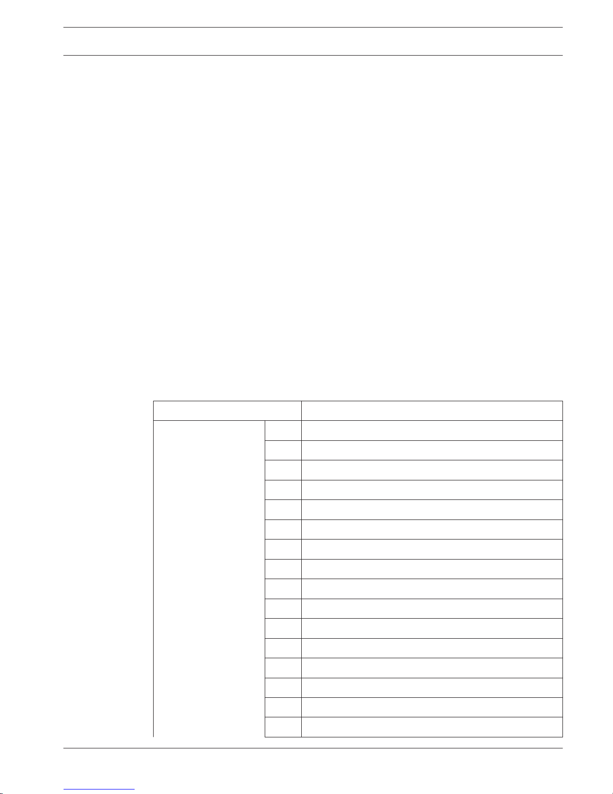
Single-Button arm / disarm Report = 253
Keyswitch arm / disarm Report = 254
Code Permissions
Tamper Reset by User
The AMAX panel may allow tamper reset by user code. If this option is disabled, the installer
code only may perform tamper reset.
Arm / Disarm Installer
The AMAX panel may allow arm / disarm by using the installer code. If this option is disabled,
the installer code is not allowed to perform arm / disarm.
Zones
Add / Delete Zone
Based on zone numbers, when adding or changing each zone, it is required to specify the area,
select the zone functions and select the module of zone source.
When the zone is selected to 0, i.e., the zone is not used, any address set on the zone function
and module selection are invalid.
Zone Module
The AMAX panel supports onboard zones, keypad zones, AMAX 3000 / 4000, and DX2010
zones and RF zones.
Zone Function / Type
Zone Function Option Description
Zone Type 00 Zone not used
01 Instant
02 Interior instant
03 Delay
04 Interior delay
05 Follower
06 Interior follower
07 24-hour
08 Key-switch toggle
09 Key switch on / off
10 24-hour panic
11 24-hour fire
12 24-hour fire with verification*
13 Tamper
14 Bolt contact
15 External fault
7.2.5
7.3
7.3.1
AMAX panel 4000 / AMAX panel 4000
EN
Settings | en 47
Bosch Sicherheitssysteme GmbH Installation Guide 2014.4 | 01 | F.01U.267.112
Page 48
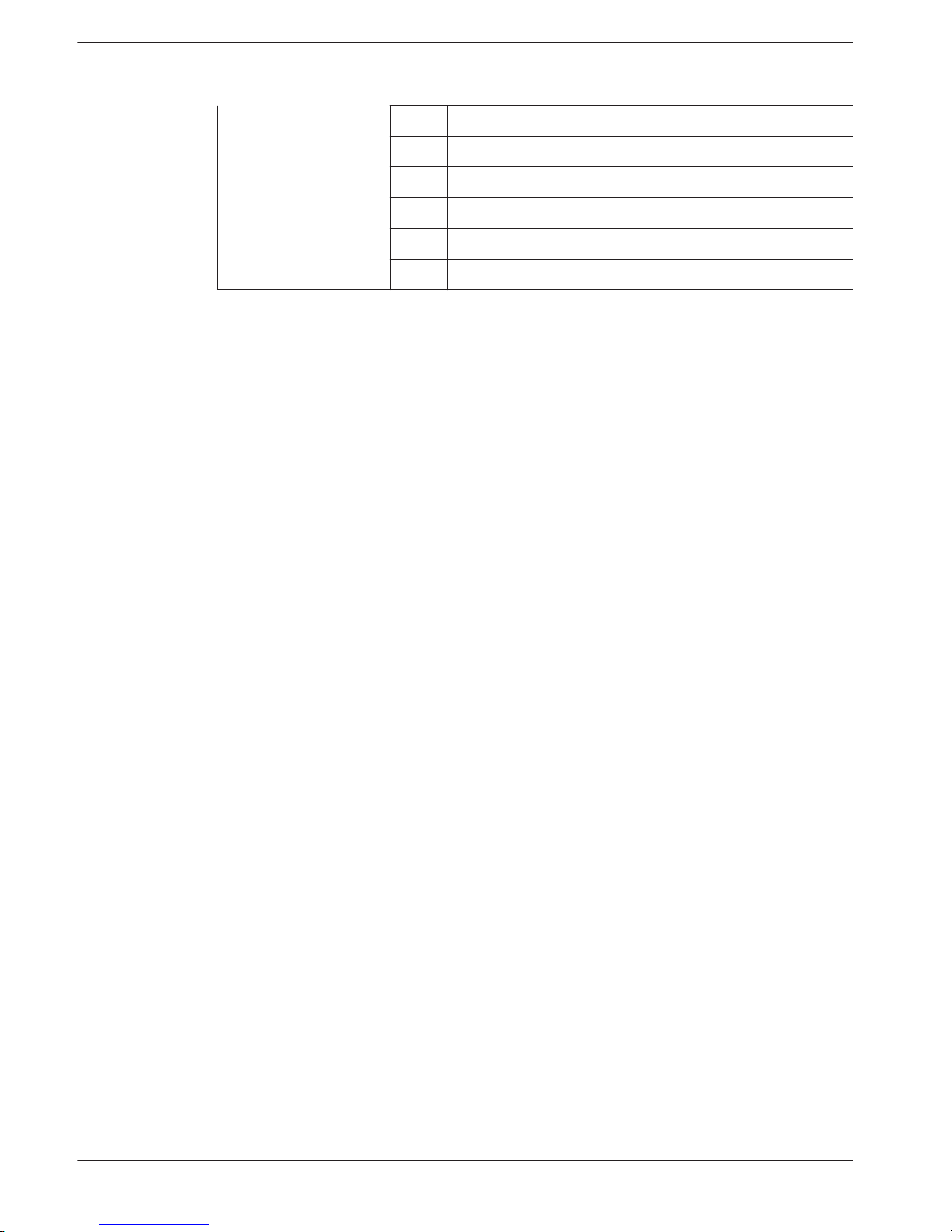
16 Delay exit
17 Interior delay exit
18 Technical alarm
19 Reset
20 Instant without reset
21 Reserved
* AMAX 4000 zone 1 only
00 – Zone Not Used
If a zone is not used, program the zone type location to 0. An EOL resistor is not required if
this zone type is not used. This zone type never activates the sirens or the dialer.
01 - Instant
The instant zone will perform as below:
1. Disarm:
– Zone normal - no alarm / no report
– Zone triggered - no alarm / no report
2. AWAY Arm:
– Zone normal - no alarm / no report
– Zone triggered - alarm / report
– (Zone triggered during exit time no alarm / no report)
– (Zone triggered during entry time alarm / report is delayed for 30 second or entry
time is expired, when system is disarmed before, no report)
3. STAY Arm:
– Zone normal - no alarm / no report
– Zone triggered - alarm / report
– (Zone triggered during exit time no alarm / no report)
– (Zone triggered during entry time alarm / report is delayed for 30 second / entry time
is expired, when system is disarmed before, no report) When Zone is triggered, not
bypassed and system is forced to arm, a Zone fault report is sent.
– When the system is disarmed and zone is not restored before, a Zone fault restore
report is sent.
02 - Interior Instant
The interior instant zone will perform as below:
1. Disarm:
– same as the instant zone disarm status
2. AWAY Arm:
– same as the instant zone AWAY arm status
3. STAY Arm:
– This zone will be Ignored and performed as disarm. Refer to Keypad Indicators to see
how the zone is displayed during exit time
– When zone is triggered, not bypassed and system is forced to arm, a zone fault
report is send
– When system is disarmed and zone is not restored before, a zone fault restore report
is sent
03 - Delay
The delay zone will perform as below:
48
en | Settings
AMAX panel 4000 / AMAX panel 4000
EN
2014.4 | 01 | F.01U.267.112 Installation Guide Bosch Sicherheitssysteme GmbH
Page 49

1. DISARM: same as instant zone disarm status
2. AWAY Arm:
– Zone normal - no alarm / no report
– Zone triggered - entry time starts - no alarm / no report
– Disarming during entry time - no alarm / no report
– Zone triggered - during exit time - no alarm / no report
– Zone triggered - during entry time - no alarm / no report
– Zone triggered - entry time is expired - alarm / report
– (report is delayed for 30 seconds, when system is disarmed before, no report)
3. STAY ARM: same as AWAY ARM performance.
– First delay zone will start the entry time; all other delay zones will follow
– When system is disarmed and zone is not restored before, a zone restore report is
sent
04 - Interior Delay
The interior delay zone will perform as below:
1. Disarm: same as the instant zone disarm status
2. AWAY Arm: same as the delay zone AWAY arm status
3. STAY Arm:
– This Zone will be ignored and performed as disarm
– Refer to Keypad Indicators to see how the zone is displayed during exit time
05 - Follower
The follower zone will perform as below:
1. Disarm:
– same as the instant zone disarm status
2. AWAY Arm:
– Zone normal - no alarm / no report
– Zone triggered – alarm / report
– Zone triggered - during exit time - no alarm / no report
– Zone triggered - during entry time - no alarm / no report
– The remaining delay time is handed over from the delay zone to the follower zone.
– The follower zone will performance as the same as a delay zone.
– If there are two or more zones programmed as delay zones and both are triggered,
the follower zone will follow the first triggered delay zone
3. STAY ARM: same as the delay zone.
06 - Interior Follower
The interior follower zone will perform as below:
1. Disarm: same as the instant zone disarm status
2. AWAY Arm: same as the follower zone AWAY arm status
3. STAY Arm:
– This zone will be ignored and performed as disarm
– Refer to Keypad Indicators to see how the zone is displayed during exit time
07 - 24 Hour
The 24 - hour zone will perform as below:
1. Disarm:
– Zone normal - no alarm / no report
– Zone triggered - alarm / report
AMAX panel 4000 / AMAX panel 4000
EN
Settings | en 49
Bosch Sicherheitssysteme GmbH Installation Guide 2014.4 | 01 | F.01U.267.112
Page 50
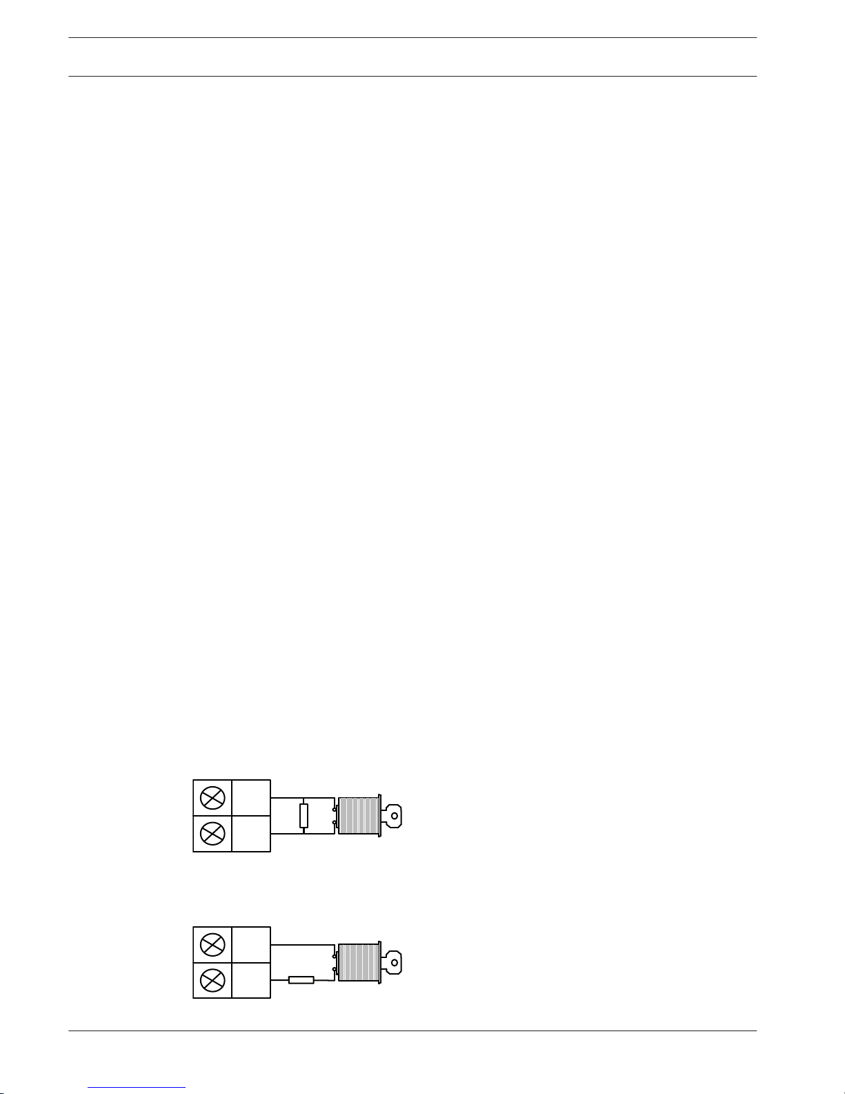
2. AWAY Arm:
– Zone normal - no alarm / no report
– Zone triggered - alarm / report
– Zone triggered - during exit time - alarm / report
– Zone triggered - during entry time - alarm / report
3. STAY Arm: same as AWAY arm performance.
– A 24 - hour zone does not send a restore report until the zone is restored
08 - Key Switch Toggle
The key switch toggle zone will perform as below:
1. Disarm:
– Zone normal - no action
– Zone triggered - activate AWAY arm / report
2. AWAY Arm:
– Zone normal - no action
– Zone triggered - activate disarm / report
3. STAY Arm:
– Zone normal - no action
– Zone triggered - activate disarm / report
This zone will ignore all other programming items, such as bypass, forcing arm.
When the system is armed in this mode, the keypad activates two beeps and report sent is by
User Code 254.
09 - Key switch On / Off
The Key Switch on / off zone will perform as below:
1. Disarm:
– Zone normal - no action
– Zone triggered - activate AWAY arm / report
2. AWAY Arm:
Zone normal - activate disarm / report
Zone triggered - no action
3. STAY Arm:
– Zone normal - activate disarm/ report
– Zone triggered - activate AWAY arm/ report
Wiring Diagram for key-switch Zone: short for arm. The momentary time is capable of lasting
Minimum 300ms.
COM
Zone
Wiring Diagram for key-switch Zone: open for arm. The momentary time is capable of lasting
Minimum 300ms.
COM
Zone
50
en | Settings
AMAX panel 4000 / AMAX panel 4000
EN
2014.4 | 01 | F.01U.267.112 Installation Guide Bosch Sicherheitssysteme GmbH
Page 51
When the key-switch operates the arm / disarm, the keypad sounds two beeps and report sent
to the system by User Code 254
Notice!
As the key-switch operates the arm / disarm successfully, the siren sounds short to indicate
it.
11 – 24 Hour Fire
The Fire zone will perform as below:
1. Disarm:
– Zone normal - no alarm / no report
– Zone triggered - alarm / report
2. AWAY Arm:
– Zone normal - no alarm / no report
– Zone triggered - alarm / report
– Zone triggered - during exit time - alarm / report
– Zone triggered - during entry time - alarm / report
3. STAY Arm: same as AWAY arm performance
– A fire zone does not send a restore report until the zone is restored
13 - Tamper
The tamper zone will perform as below:
1. Disarm:
– Zone normal - no alarm / no report
– Zone triggered - alarm / report
2. AWAY Arm:
– Zone normal - no alarm / no report
– Zone triggered - alarm / report
– Zone triggered - during exit time - alarm / report
– Zone triggered - during entry time - alarm / report
3. STAY Arm: same as AWAY arm performance
– A tamper zone does not send a restore report until the zone is restored
12- 24 Hour Fire with Verification (only possible for AMAX 4000 Zone 1)
The 24 - hour fire with verification zone will perform as below:
1. Disarm:
– Zone normal - no alarm / no report
– Zone triggered: After the first alarm, the AMAX panel performs a fire verification reset
(10 seconds) and then waits a period up to two minutes for a second alarm. If a
second alarm occurs within this period, the AMAX panel indicates a fire alarm.
Otherwise, the AMAX panel resets back to its normal condition. At the end of the two
minute period an unverified fire alarm is logged and reported. A fire zone does not
send a restore report until the zone is restored
2. AWAY Arm: same as disarm performance
3. STAY Arm: same as disarm performance
14 - Bolt Contact
The Bolt-Contact zone will perform as below:
1. Disarm:
AMAX panel 4000 / AMAX panel 4000
EN
Settings | en 51
Bosch Sicherheitssysteme GmbH Installation Guide 2014.4 | 01 | F.01U.267.112
Page 52

– Zone normal - no alarm / no report
– Zone triggered - no alarm / no report
2. AWAY Arm:
– Zone normal - no alarm / no report
– Zone triggered - no alarm / no report
– Zone triggered - during exit time - no alarm / no report
– Zone triggered - during entry time - no alarm / no report
3. STAY Arm: same as AWAY Arm performance.
– This zone is mainly for prevention of arming (to ensure exit/entry door is locked
before arming the system and no alarm occurs when entering the premise through
the entry/exit door)
15 - External Fault
The fault zone / input will perform as below:
1. Disarm:
– Zone normal - no alarm / no report
– Zone triggered - fault / report
2. AWAY Arm:
– Zone normal - no alarm / no report
– Zone triggered - alarm / report
– Zone triggered - during exit time - fault / report
– Zone triggered - during entry time - fault / report
3. STAY Arm: same as AWAY Arm performance
– The restore report will be sent when the zone is restored
16 - Delay Exit
The delay exit zone will perform as below:
1. DISARM: same as Instant zone disarm status
2. AWAY Arm:
– Zone normal - no alarm / no report
– Zone triggered - entry time starts - no alarm / no report
– Disarming during entry time - no alarm / no report
– Zone triggered - during exit time - no alarm / no report / abbreviates remaining time
for exit to 5 s
– Zone triggered - during entry time - no alarm / no report
– Zone triggered - entry time is expired - alarm / report (report is delayed for 30
second, when system is disarmed before, no report)
3. STAY ARM: same as AWAY ARM performance
– First delay zone will start the entry time; all other delay zones will follow
– When system is disarmed and zone is not restored before, a zone restore report is
sent
17 - Interior Delay Exit
The Interior delay exit zone will perform as below:
1. Disarm: same as the Instant zone disarm status
2. AWAY Arm: same as the delay exit zone AWAY arm status
3. STAY Arm:
– This zone will be Ignored and performed as disarm
– Refer to Keypad Indicators to see how the zone is displayed during exit time
52
en | Settings
AMAX panel 4000 / AMAX panel 4000
EN
2014.4 | 01 | F.01U.267.112 Installation Guide Bosch Sicherheitssysteme GmbH
Page 53

18 - Technical Alarm
The technical alarm zone will perform as below:
1. Disarm:
– Zone normal - no alarm / no report
– Zone triggered - alarm / report
2. AWAY Arm:
– Zone normal - no alarm / no report
– Zone triggered - alarm / report
– Zone triggered - during exit time - alarm / report
– Zone triggered - during entry time - alarm / report
3. STAY Arm: same as AWAY arm performance.
– A technical zone does not send a restore report until the zone is restored
19 - Reset
The reset zone will perform as below:
1. Disarm:
– Zone normal - no alarm / no report
– Zone triggered – performs system reset / no report
2. AWAY Arm:
– Zone normal - no alarm / no report
3. STAY Arm: same as AWAY arm performance
20 - Instant Without Reset
The instant report zone will perform as below:
1. Disarm:
– Zone normal - no alarm / no restore report
– Zone triggered - no alarm / sends report
2. AWAY Arm:
– Zone normal - no alarm / no restore report
– Zone triggered - no alarm / sends report
– Zone triggered - during exit time – no alarm / sends report
– Zone triggered - during entry time – no alarm / sends report
3. STAY Arm: same as AWAY Arm performance
Zone in Area
Each zone is assigned to an area. This assignment influences the way how zones are indicated
on keypads. Refer to Zone Indication Keypad and Event Log, page 59
RF Zones
The AMAX panel 3000 / 4000 identifies RF zones by Zone RFID. AMAX Keypad programming
supports entering RFID automatically for Radion devices. When zone RFID is asked, press *
button for 3 second toggles between AUTO and MANUAL mode. When MANUAL is selected,
enter 9 – digit RFID using pin keys. When AUTO is selected, trigger RF device in order to enter
RFID automatically.
Hardwired Input Zones
On-board Inputs:
The AMAX panel provides onboard hard-wired inputs. An additional input is provided for the
enclosure tamper.
AMAX panel 4000 / AMAX panel 4000
EN
Settings | en 53
Bosch Sicherheitssysteme GmbH Installation Guide 2014.4 | 01 | F.01U.267.112
Page 54
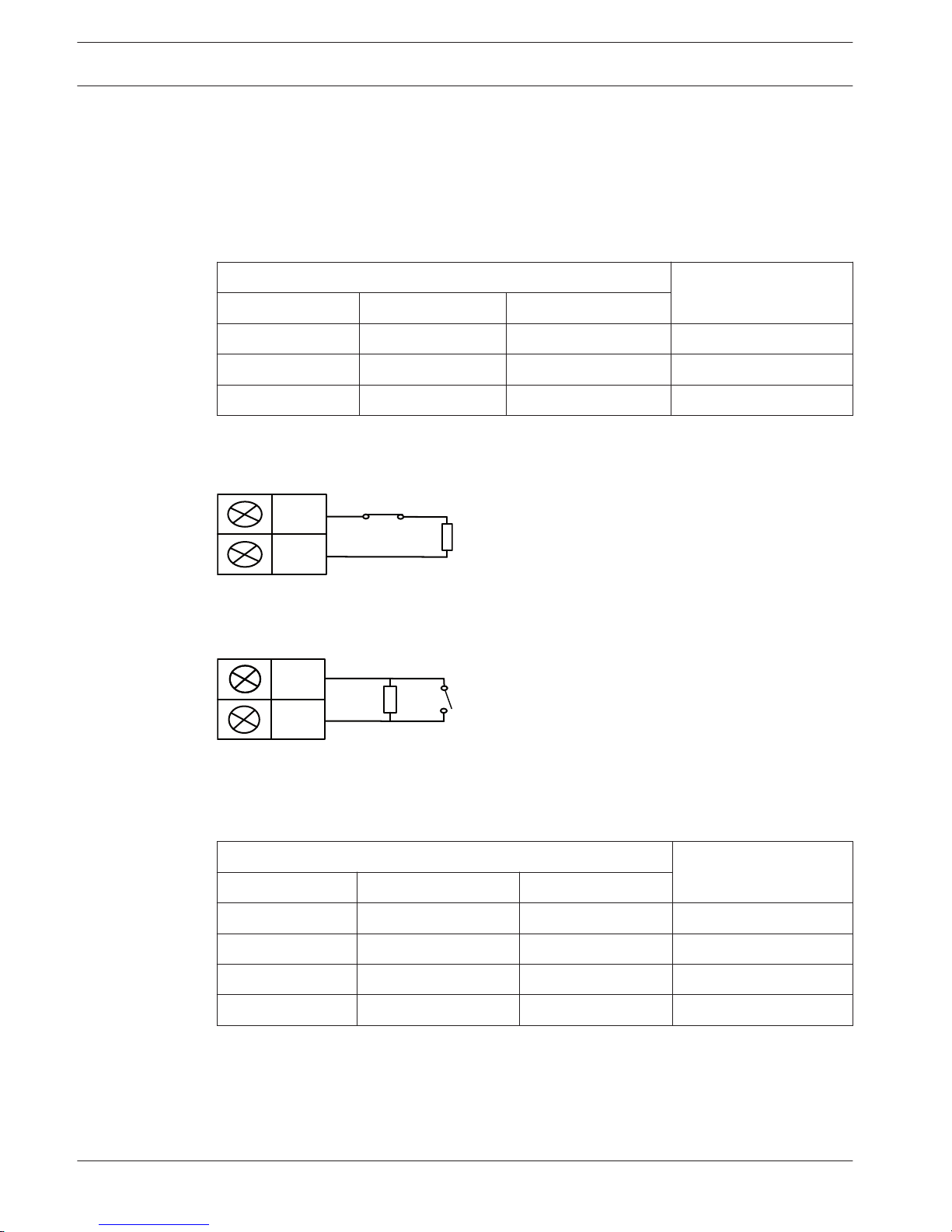
On-board Zone Response Time:
Each on-board zone response time is:
Zone status trigger time >= 400ms, must response
Zone status trigger time < 300ms, no response
On-board Zone EOL
1. Single EOL: If the zone tamper function is not selected, each zone uses a single 2.2 Kilo
ohm EOL. The panel can detect the zone as short, normal or open.
Loop Resistance (ohm) Zone Status
Min Type Max
0 1430 triggered
1650 2200 2750 normal
2970 ∞ triggered
The detectors (sensors) will be connected between zone and COM terminal through EOL
series (open triggered) or parallel connection (short triggered).
COM
Zone
The detectors (sensors) will be connected between zone and COM terminal through EOL
series connection (open triggered) or EOL parallel connection (short triggered).
COM
Zone
The panel sets the short / open as activate when connecting with single EOL.
The valid zone number is 1-8 for AMAX 2100 / 3000, 1-16 for AMAX 4000
1. Dual EOL: If the tamper supervision is set, we only can use the NC contact point. The EOL
status is:
Loop resistance (ohm)
Zone Status
Min Type Max
o 1430 tamper
1650 2200 2750 normal
2970 4400 4950 triggered
5220 ∞ tamper
Using one 2.2 Kilo resistor as EOL of the tamper zone, which works together with the zone
EOL 2.2 Kilo.
54
en | Settings
AMAX panel 4000 / AMAX panel 4000
EN
2014.4 | 01 | F.01U.267.112 Installation Guide Bosch Sicherheitssysteme GmbH
Page 55
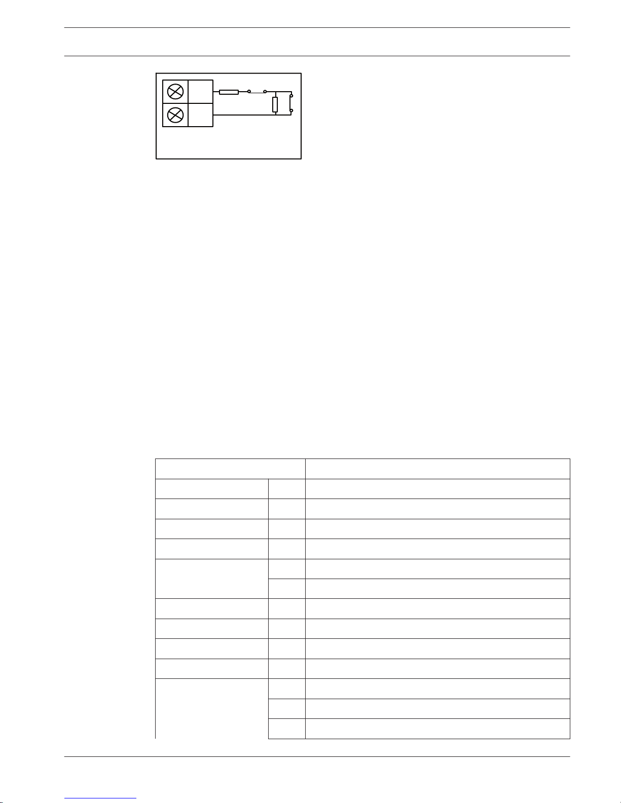
COM
Z3
BBBBB7DPSHU6ZLWFK
BBBBB=RQH6ZLWFK
1
2
On-board Tamper Input
A separate input is provided for enclosure tamper. The response time of the tamper input can
be set either to 400ms or 150ms.
Pulse Count Duration
Pulse Count Duration
The pulse code duration defines the period for the zone pulse count feature.
See also
– Zone Function Settings, page 55
Cross Zone Timer
Cross Zone Timer
The cross zone timer defines the period for the cross zone feature.
See also
– Zone Function Settings, page 55
Zone Function Settings
Zone function option Description
Force arm / bypass 0 Disabled
1 Force arm
2 Bypass
3 All
Silent alarm / Chime
mode
0 Disabled
1 Silent alarm
2 Chime mode
3 All
Zone pulse count 0 Disabled
1-9 1-9 pulses
Zone lockout 0 Disabled
1 1 times alarm lockout
2 3 times alarm lockout
7.3.2
7.3.3
7.3.4
AMAX panel 4000 / AMAX panel 4000
EN
Settings | en 55
Bosch Sicherheitssysteme GmbH Installation Guide 2014.4 | 01 | F.01U.267.112
Page 56
3 6 times alarm lockout
4 Alarm duration
Zone tamper 0 Disabled
1 Enabled
Zone status report 0 No report required
1 Receiver 1
2 Receiver 2
3 Receiver 3
4 Receiver 4
5 Receiver 1, 2, 3, and 4
6 Receiver 1 (2, 3, and 4 for backup)
7 Receiver 1 (2 for backup) and receiver 3 (4 for backup)
Unverified alarm
report / cross zone
0 Disabled
1 Unverified alarm report
2 Cross zone
3 All
Domestic no. Follow 'alarm report' option's logic. range 0-7
0 No reports allowed
1 Report to destination 1
2 Report to destination 2
3 Report to destination 3
4 Report to destination 4
5 Report to destination 1 ,2, 3, 4
6 Report to destination 1 (where 2, 3, and 4 backup)
7 Report to destination 1 (where 2 Backup) and 3 (where 4
backup)
Zone Bypass
If this option is enabled, the operator can bypass zones before arming the system. If this
option is disabled, manual bypass of the zone will not be available. After manual bypass of the
zone, a zone bypass report will be sent.
The zone bypass is valid in one arming period only and will be resumed after disarming. Before
disarming, the bypassed zones will ignore all zone triggering and restoration events.
The key switch zone cannot be bypassed.
56
en | Settings
AMAX panel 4000 / AMAX panel 4000
EN
2014.4 | 01 | F.01U.267.112 Installation Guide Bosch Sicherheitssysteme GmbH
Page 57

Forced Arming
If this option is selected, the system can be armed when the zone is in triggering status. If this
option is not selected, the system will not allow the PIN holder to arm the system unless the
zone with problems has resumed to normal status or been manually bypassed.
The arming with a zone in triggering status is called forced arming.
When the operating system arms:
– When the keypad or key switch zone is used to execute system arming, the system will
show the zone status at first. If a zone in triggering status is not bypassed and the forced
arming option is in disabled status, it cannot be successfully armed.
– When the keypad or key switch zone is used to execute system arming, the system will
show the zone status at first. If a zone in triggering status is not bypassed and the forced
arming option is in enabled status, the system will be successfully armed. If the zone is
still not recovered at the end of the exit delay time, the system will show the fault report
of the zone.
– When the fault is recovered, a zone recovery report will be sent.
The exceptions to forced arming option:
– In telephone and programming software remote arming, forced arming is available no
matter the zone is programmed as enabled or disabled forced arming.
Silent Alarm
Enabling this option can set the zone to mute alarm. Silent alarm will not trigger the output of
keypad buzzer and the output of the type of event of system audio alarm, but can trigger the
output of the type of event of system alarm (both sound and silent) and the alarm event can
still be transmitted according to programming path.
Zone Locking
The zone locking option of each zone can be set to a non-locking 1 time locking, 3 time
locking, 6 times locking and follow alarm time.
For unlocking, set the zone locking option to 0 to disable the zone locking function.
3 times of alarm locking
If the locking option is set to 2, the zone can only transmit up to 3 times of alarm report in
each arming period. After zone re-disarming re-arming, the locking count will be reset.
The AMAX panel will process locking according to the following logic:
1. When the zone or zone tamper is trigger and siren alarm is resulted, within the period of
alarm output time, the AMAX panel will ignore the status detection of the zone.
2. When the alarms rings 3 times, the zone will be locked.
3. If the alarm occurs in the locked zone, the zone will send zone fault report.
4. Before the end of the alarm output time, ten zone recovery event will not be transmitted.
5. If the zone locking option is disabled, the times of alarms will not be restrained. Even
when other zones are locked, that zone can still generate the alarm.
6 times of alarm locking
Similar to 3 times of alarm locking, with alarm limited to not more than 6 times.
Locking within the period of alarm output time. Repeating the process of alarm locking in the
period of alarm output time, without limit to times.
Zone Tamper
The system supports the tamper detection of the zone. This function ensures that the zone is
in normal operating status. The process is as follows:
1. If 24-hour zone tamper is enabled, the wiring method for two-terminal resistor is
required.
AMAX panel 4000 / AMAX panel 4000
EN
Settings | en 57
Bosch Sicherheitssysteme GmbH Installation Guide 2014.4 | 01 | F.01U.267.112
Page 58

2. If the zone detects that the 24-hour tamper is triggered, the zone tamper alarm will be
processed the same as 24-hour zone.
3. If the zone detests zone alarm, the zone will process according to specified zone type.
If the zone is programmed to disable 24-hour zone tamper, the wiring method for singleterminal resistor is required. If the zone detests alarm, the zone will process according to
specified zone type.
Zone Status Reporting
The AMAX panel reports the zone status according to the specified path, including alarm, zone
fault, zone bypass and zone tamper alarm.
Zone Chime Mode
The system will support the chime mode.
The process is as follows:
– If the chime mode is used and a zone is triggered the keypad buzzer will sound for 1
second (only in disarmed status)
Zone Pulse count
The system will support the pulse count mode.
The process is as follows:
– pulse count duration time must be configured (Refer to chapter 9.1 Communication and
Report Settings)
– pulse count for a zone can be set to a value between 1 and 9 (0 = disabled)
The process is as follows:
– an alarm is only created, if the zone is triggered as many times as the value “pulse count”
within the time “count duration”
Domestic no.
The system will support the domestic call mode.
The process is as follows:
– If the domestic call mode is configured for a zone and an alarm from this zone is created
the alarm will be reported to the destination(s) configured and needs acknowledgement
Cross Zone
The cross zone option works as follows:
Prerequisites:
– At least two zones in the same area have option Cross Zone enabled
– System option Cross Zone Timer is set to a value higher than 0
When one of these zones is triggered for more than 20 seconds, an alarm is created.
When one of these zones (the first zone) is triggered for a shorter time than 20 seconds, the
cross zone timer starts, no alarm is created at this time
– When no more zones (with cross zone option) are triggered within the cross zone time,
no alarm is created
– When the first zone is triggered twice or more within the cross zone time, no alarm is
created
– When a second zone or further zones (with cross zone option) is / are triggered within
the cross zone time, then an alarm is created for all triggered zones
– When the first zone or one of the other zones (with cross zone option) is / are triggered
twice or more after cross zone time is expired, the timer restarts
58
en | Settings
AMAX panel 4000 / AMAX panel 4000
EN
2014.4 | 01 | F.01U.267.112 Installation Guide Bosch Sicherheitssysteme GmbH
Page 59

Unverified Alarm Report
Enables / disables option unverified alarm report. When a cross zone is triggered, but no alarm
is created, system creates an unverified alarm in order to report. System reports unverified
alarms if option unverified alarm report is enabled.
Zone Indication Keypad and Event Log
Zones may be indicated on keypads and in event logs with a number that are different from
the zone number used for programming and hardware input.
One area system
Zones are indicated on keypads according to the zone numbers. When one zone is disable the
indication number of all following (higher) zone numbers will shift to a value decreased by
one.
Multi area system
Only zones assigned to one area are indicated on an area keypad in order beginning with 1
and by following the order of zone numbers.
Examples:
Examples:
AMAX 3000 / 4000: In a 1 Area or Area 1 system keypad zone number 17 should be indicated
on a 16 zone LED keypad. After disabling zone 16 (or another one in range 1 to 16) zone
number 17 is indicated on keypad as number 16.
AMAX 2100: In a one area system keypad zone number 17 should be indicated on an 8 zone
LED keypad. After disabling zone 5 zone number 17 is indicated on keypad as number 5.
7.3.5
AMAX panel 4000 / AMAX panel 4000
EN
Settings | en 59
Bosch Sicherheitssysteme GmbH Installation Guide 2014.4 | 01 | F.01U.267.112
Page 60
In a multi area system the following table shows area assignment and keypad indication of
zones:
Zone Number Area Indication keypad area 1 Indication keypad area 1
1 2 1
2 2 2
3 1 1
4 1 2
5 1 3
6 1 4
7 2 3
8 2 4
9 2 5
10 2 6
11 1 5
12 1 6
Keypads and Areas
Keypad Area
Master Keypad
User access to a master keypad differs from user access to an area keypad. The master keypad
switches to the master keypad mode or to the area that the user declares after entering the
user code.
The AMAX panel supports master keypads. The arming / disarming, area alarm, AC power fault,
system fault and system event of each area can be displayed on the master keypad. It is not
possible to execute arming / disarming and bypass operation on the master keypad. When
relevant operations are made to the area, the master keypad should be switched to the
corresponding area.
Area Keypad
It is possible to operate each area with a single or multiple independent keypads.
Each area keypad can only operate the corresponding area of the programming,
When the area keypad has not corresponding zones, the area keypad cannot be used to
execute zone-related operations such as arming / disarming and bypass, but can be used to
execute operations without relations to the zone, e.g. event inquiry.
Each area keypad can display the status of the zone belonging to the area. However, for IUIAMAX3- LED8 keypad, IUI-AMAXLED 8 keypad and IUI-AMAX-LCD 8 keypad, each area can
display up to 8 zones and cannot display other zones, but can report zone events. For IUIAMAX3LED16 keypad, each area can display up to 16 zones and cannot display other zones,
but can report zone events. Keypad IUI -AMAX4-TEXT can display up to 64 zones.
7.4
7.4.1
60 en | Settings
AMAX panel 4000 / AMAX panel 4000
EN
2014.4 | 01 | F.01U.267.112 Installation Guide Bosch Sicherheitssysteme GmbH
Page 61

For any area, the logic numbers of the zones are displayed on the LED / Icon LCD keypad and
logic numbers or zone names of the zones are displayed on the keypad instead of actual
physical numbers. For example: The zones 1, 2, and 3 of 1 area or area 1 displayed on the
keypad are actually zones 20, 31, and 37.
Area Timing
The AMAX panel supports separate entry and exit delay times for each area.
Exit Delay
The programming range is 0 - 255 seconds. In the mode of system arming, the keypad will
beep during exit and will make continuous long beep sound in the last 10 seconds to notify
the exit time is coming to an end.
Entry Delay
The programming range is 0 - 255 seconds. Entry delay time starts when a delay zone is
triggered in armed state.
Common Area
Area 1 can be used as a common area or an independent area. Common area ancillary acts are
as follows:
– Only all belonged independent areas are armed, the common area can be armed
– When a relevant ancillary area is perimeter arming, the common area will be perimeter
arming too
– When a relevant ancillary area is disarmed, the common area will be armed
– If any zones under common zones are in triggered or tamper status and the forced arming
is disabled, the common area cannot be armed
Keypad Tone / Lockout
Keypad Alarm Tone
The AMAX panel supports to enable or disable keypad alarm tone.
Keypad Lock Count
The number of attempts to enter a wrong user code can be set from 1 to 15 in order to
supervise valid user access. The keypad will be locked for 3 minutes, when the number of
attempts reaches the declared value.
System
This chapter describes eight categories of system settings including the system date and time,
telephone settings, etc.
System Setting
Date and Time
The AMAX panel has a 24-hour clock and a 12-month calendar that need to be set during
installation. The order is year, month, day, hour, and minute, with each item occupying two
digits [YY] [MM] [DD] [HH] [MM].
Fault Sound Reminder
When the command [2] [1] is used for fault inquiry, the keypad can be programmed to sound
prompt tone to indicate new system fault. The system is defaulted to enable. In case of a new
fault, all keypads will sound a short beep once a minute.
7.4.2
7.4.3
7.4.4
7.5
7.5.1
AMAX panel 4000 / AMAX panel 4000
EN
Settings | en 61
Bosch Sicherheitssysteme GmbH Installation Guide 2014.4 | 01 | F.01U.267.112
Page 62

AC Fault Delay Time
The fault report will be delayed for 1 hour or 10 minutes, or transmitted along with the other
reports. The AC power fault event will be displayed on the keypad 1 hour, or 10 minutes later.
Date / Time Fault
In case of date/time settings fault, it is possible to choose to display the fault or transmit fault
prompt tone at the same time, or to not display and stop fault prompt tone. If it is chosen to
not display, the fault prompt tone is set, and the system will prompt nothing if no date and
time are set after power-up.
Battery Check Interval
This option defines the time interval in which the battery test is carried out. Also battery test
is carried out when armed or during system power up.
Phone Line Monitor
If the option is enabled, the system supervises whether the phone line is broken or
disconnected.
Siren Supervision
If the option is enabled, the system supervises whether the siren is shortened or
disconnected.
Quick Arming
Without any PINs, system quick arming can be made by pressing and holding the keypad # for
3 seconds, or the quick perimeter arming can be made by pressing and holding the keypad *
for 3 seconds.
Installer Access Until Next Arming
Before using installer access, a standard user has to enable installer access first. If the option
installer access until next arming is enabled, installer access permission is limited to next
arming.
Force Arm When System Is In Trouble Condition
If the option is enabled, an area can be force armed however there is trouble condition.
Event Record Count per Set/Unset Period
Option event record count per set / unset period defines the maximum number of records for
an event within the set / unset period.
Language Version
The AMAX panel supports different languages. Select one of the versions available.
Keypad 2 Button Alarm
If the option is enabled, an area can be force armed. However there is a trouble condition.
The emergency alarm will be transmitted, if 1 and 3, or * and # are pressed and held
simultaneously. The fire alarm will be transmitted, if 4 and 6 are pressed and held
simultaneously. The silent keypad emergency alarm will be transmitted, if 7 and 9 are pressed
and held simultaneously.
System Tamper Indication In Area
This option defines where the system tamper event is indicated. System tamper indication can
be assigned to either the area where zone 1 is located in or to all Areas.
Zone Tamper Bypass when DEOL Zone is Bypassed
If the option is enabled, system creates a tamper alarm when DEOL zone is tampered, even
when this zone is bypassed. Modify address 0184 in order to change parameter. This function
is only accessible in address programming.
Enclosure Tamper Timing
The AMAX panel supports different reaction times for the onboard tamper used for panel
enclosure. The reaction time is default 400 ms and can be changed to 150 ms.
62
en | Settings
AMAX panel 4000 / AMAX panel 4000
EN
2014.4 | 01 | F.01U.267.112 Installation Guide Bosch Sicherheitssysteme GmbH
Page 63
Reset to Factory Default Settings
The factory default can be reset with the ‘resetting to factory default’ pads on the main board
of the AMAX panel.
1. Disconnect the AC power supply and backup battery to the AMAX panel.
2. Short-circuit the ‘resetting to factory default’ pads.
3. These set of pads are located at the top on the printed circuit board of the AMAX panel.
4. Powering up is done when the bonding pads are short-circuited.
5. Quick flash of the red LED indicator on the printed circuit board of the AMAX panel
indicates that the factory default will be reset.
6. All programming parameters are reset to factory default immediately after releasing the
short - circuited bonding pads.
Notice!
If the default pads are short-circuited for over 10 seconds after power-up, the AMAX panel
will discard resetting to factory default.
System View
Fault Analysis
AMAX panel can display eight categories of 41 kinds of system failure.
7.5.2
AMAX panel 4000 / AMAX panel 4000
EN
Settings | en 63
Bosch Sicherheitssysteme GmbH Installation Guide 2014.4 | 01 | F.01U.267.112
Page 64
1 Accessory Module Failure
1
1 - 2
Network / IP Module 1 - 2 Failure
2
1 - 2
Output Expansion Module 1 - 2 Fault
3
1 - 6
Output Expansion Module 1 - 6 Fault
4
1
Module DX4010 Missing
2
Printer Missing
3
Printer Fault
5
1 RF Receiver 1 Fault
2 RF Receiver 1 Missing
3
RF Receiver 1 Jammed
6
1
RF Sensor Missing *
2
RF Sensor Fault *
7
1 - 8
RF Repeater 1-8 Missing
8
1
Configuration Conflict Sensors *
2
Configuration Conflict Repeaters *
3
Configuration Conflict Keyfobs *
2
1
2
3
1 - 2
Panel Aux Power 1 - 2 Fault
4
1 - 2
Bosch Option Bus 1 - 2 Power Fault
5
1 - 8
RF Repeater 1-8 AC Power Fault
6
1 - 8
RF Repeater 1-8 Battery Fault
7
8
Network / IP Module 1 Failure
Output Expansion Module Failure
RF Config Failure
RF Repeater Failure
RF Sensor Failure
RF Receiver Failure
Printer Failure
Input Expansion Module Failure
RF Repeater Battery Failure
RF Sensor Power Failure *
RF Keyfob Battery Failure *
Power Failure
Panel AC Failure
Panel Low Battery
Panel Aux Power Failure
Bosch Option Bus Power Failure
RF Repeater AC Power Failure
64 en | Settings
AMAX panel 4000 / AMAX panel 4000
EN
2014.4 | 01 | F.01U.267.112 Installation Guide Bosch Sicherheitssysteme GmbH
Page 65
3
1
Onboard Output 1 Fault
2
Onboard Output 2 Fault
4
5
1
6
1
Communication Fault 1
2
Communication Fault 2
3
Communication Fault 3
4
Communication Fault 4
5
Phone Line Fault
7
Tamper
1
2
Keypad 1 – 16 Tamper
3
1 - 6
Zone Expansion Module 1 - 6 Tamper
4
Sensor Tamper DEOL
5
Zone type Tamper
6
1
Keypad Lock out
7
1
RF Receiver Tamper
8
1 - 8
RF Repeater Tamper
8
External Fault Zone 1-16
Keypad Failure
System Failure
Communication Failure
Keypad 1 – 16 Fault
Date Time not set
1 - 16
1 - 16
1 - 16
1 - 16
Output Failure
Keypad Tamper
System Tamper
1 - 16
External Failure
Zone Expansion Module Tamper
Zone Tamper DEOL
Zone type Tamper
Keypad Lock out
RF Receiver Tamper
RF Repeater Tamper
For more information about fault inquiry, see Trouble Fault Inquiry, page 140.
FW Version
AMAX keypad displays Firmware Version.
AMAX panel 4000 / AMAX panel 4000
EN
Settings | en 65
Bosch Sicherheitssysteme GmbH Installation Guide 2014.4 | 01 | F.01U.267.112
Page 66

Outputs and Sirens
Outputs
Onboard / Extension Output
The AMAX panel is equipped with on-board outputs and supports DX3010 output extension
modules with each extension module supporting 8 relay outputs.
When on-board output 1 or 2 fails due to a short circuit or open circuit, as long as there is a
backup power supply, the output fault will not affect the normal operation of the whole
system, but will be detected by the system.
Each output is programmable and can be set to follow multiple events.
Depending on the type of output event, the output parameters can be defined as area output
or follow zone alarm output. The output polarity of each output can be programmed and
defined as three modes: continuous output, pulse output or inverted.
The maximum time of each output is specified by programming and will be automatically reset
after expiration.
Output Events
0 - Not used
1 - disarmed 0 = all areas, 1 -16 = areas1 - 16
The output operates on below conditions:
1. System disarmed after system reset.
2. System operated the disarm command.
The output is reset:
1. When the system is armed.
2. When the output programmed duration is up.
2 - system armed 0 = all areas, 1-16 = areas1 - 16
The output operates on below conditions:
1. System armed after system reset.
System operated the arm command and until system is armed. (When system is operating the
arm command, the system will arm after the exit delay time is up.)
The output is reset:
1. When the system is disarmed.
2. When the output programmed duration is up.
If this duration is programmed as 000, the output will continue till the system disarmed.
3 - System Alarm
This output operates when an alarm occurs.
The output is reset:
1. When the system is disarmed and alarm is reset.
2. When the output programmed duration is up.
When a new alarm has occurred, the alarm will reset the alarm time.
If this duration is programmed as 000, the output will continue till the zone is restore or
system is disarmed.
4 - System Alarm (audile and silent)
In case of audio alarm of the system, the output will be enabled.
– Zone (alarm or tamper) programmed to disable zone silent alarm
– System tamper / DX2010 tamper / keypad tamper
– Keypad alarm (emergency alarm, fire alarm, medical aid alarm)
7.6
7.6.1
66 en | Settings
AMAX panel 4000 / AMAX panel 4000
EN
2014.4 | 01 | F.01U.267.112 Installation Guide Bosch Sicherheitssysteme GmbH
Page 67

Or in case of silent alarm of the system, the output will be enabled
– Zone (alarm or tamper) programmed to enable zone silent alarm. In case of following
conditions, the output will be reset
– Alarm reset
– Arming of the system
– Disarming of the system
In case of a new alarm event, the output time will be reset and re-timed.
When the output time is set to 000 and the alarm siren sounds for 0, the output will continue
until reset of alarm output or disarming of the system by the command of PIN 3 2 #.
The output of the following system alarm is only 1 second:
– Alarm siren test
– Pacing (tamper / alarm / reset)
– Key switch arming or- locking key switch disarming
5 - External AWAY Siren
The output is triggered when:
System is AWAY armed +zone intruder alarm (intruder alarm = instant / interior instant /
delay / interior delay / delay exit / interior delay exit / follower / interior follower / 24h (can be
silenced) / Fire (can be silenced) / Technical Alarm (can be silenced))
System is AWAY armed +tamper alarm
(no alarm when panel is disarmed)
6 - External STAY Siren
The output is triggered when:
System is STAY armed +zone intruder alarm (intruder alarm = instant / interior instant / delay /
interior delay / delay exit / interior delay exit / follower / interior follower / 24h (can be
silenced) / Fire (can be silenced) / Technical Alarm (can be silenced))
System is STAY armed +tamper alarm
(no alarm when panel is disarmed)
7 - Internal Siren
The output is triggered when:
System is AWAY armed + zone intruder alarm (intruder alarm = instant / interior instant /
delay / interior delay / delay exit / interior delay exit / follower / interior follower / 24h (can be
silenced) / Fire (can be silenced) / Technical Alarm (can be silenced))
System is AWAY armed + tamper alarm
System is STAY armed + zone intruder alarm (intruder alarm = instant / interior instant /
delay / interior delay / delay exit / interior delay exit / follower / interior follower / 24h (can be
silenced) / Fire (can be silenced) / Technical Alarm (can be silenced))
System is AWAY armed + tamper alarm
System is disarmed + zone tamper alarm
When panel is armed = one pulse activation (1sec) (enabled / disable option can be combined
with disarm)
When panel is disarmed = two pulse activation (1sec) (enabled / disable option can be
combined with arm)
When Programming mode is entered = one pulse activation (1sec) (enabled / disable option)
8 - Internal Siren with tamper
The output is triggered when internal siren with tamper.
AMAX panel 4000 / AMAX panel 4000
EN
Settings | en 67
Bosch Sicherheitssysteme GmbH Installation Guide 2014.4 | 01 | F.01U.267.112
Page 68

9 - Entry/Exit Delay Warning
Entry Delay Warning
This output operates during entry time.
The output is reset:
1. When the system disarmed.
2. When Entry Time expires.
3. When the output programmed duration is up.
Exit Delay Warning
This output operates during exit time when the AMAX panel is armed.
The output is reset:
1. When the system is disarmed.
2. When Exit Time expires.
3. When the output programmed duration is up.
If this duration is programmed as 000, the output will continue till the delay warning duration
is up.
10 - Telephone Line Fault
This output operates when a telephone line fault occurs.
The output is reset:
1. When the telephone line is restored and fault is reset.
2. When the output programmed duration is up.
If this duration is programmed as 000, the output will continue till the telephone line is
restored and fault is reset.
11 - AC Power Supply Fault
This output operates when a AC MAINS fault occurs.
The output is reset:
1. When the AC power supply is restored and fault is reset.
2. When the output programmed duration is up.
If this duration is programmed as 000, the output will continue till the AC MAINS power is
restored and fault is reset.
12 - Low Battery
This output operates when a low battery fault occurs.
The dynamic battery test is performed every 4 hours after the system is powered up and every
time the system is armed.
The output is reset:
1. Only after receiving a dynamic battery test report that the backup battery voltage is
normal and fault is reset.
2. When the output programmed duration is up.
If this duration is programmed as 000, the output will continue till battery is restored and fault
is reset.
13 - Tamper
This output operates when a tamper condition occurs.
The output is reset:
The output is reset when the output programmed duration is up.
lf this duration is programmed as 000, the output will continue till the tamper condition is
restored and tamper is reset.
68
en | Settings
AMAX panel 4000 / AMAX panel 4000
EN
2014.4 | 01 | F.01U.267.112 Installation Guide Bosch Sicherheitssysteme GmbH
Page 69

14 - External Fault
This output operates when an external fault occurs.
The output is reset:
The output is reset when the output programmed duration is up.
lf this duration is programmed as 000, the output will continue till the external fault is
restored and the fault is reset.
15 - All Faults
This output operates when a fault occurs.
The output is reset:
When the output programmed duration is up.
lf this duration is programmed as 000, the output will continue till the fault is restored and the
fault is reset.
16 - Fire Alarm
The output is triggered when fire alarm.
17 - Fire Reset
The output is triggered when fire reset.
18 - AWAY Armed
This output operates when system is AWAY armed.
The output is reset:
1. When the output programmed duration is up.
2. lf this duration is programmed as 000, the output will continue till the system is
disarmed.
19 - STAY Armed
This output operates when system is STAY armed.
The output is reset:
The output is reset when the output programmed duration is up.
lf this duration is programmed as 000, the output will continue till the system is disarmed.
20 - Reset
This output operates when a reset is performed in the system.
21 - Follow Zone Event Zone Number
The output follow type imitates the zone alarm state, when alarm or tamper is generated in
the corresponding zone, the output will be enabled. When system arming, disarming, or
output time ends, the output will be reset.
For actual output time, see Table The Value Ranges of Output Programming Options
22 - RF Keyfob button 3
The output is triggered when Keyfob Button 3 is pressed.
23 - RF Keyfob button 4
The output is triggered when Keyfob Button 4 is pressed.
24 - Chime Indication
AMAX panel 4000 / AMAX panel 4000
EN
Settings | en 69
Bosch Sicherheitssysteme GmbH Installation Guide 2014.4 | 01 | F.01U.267.112
Page 70

The output is triggered when Chime Indication.
25 - Verified Alarm
The output is triggered when Verified Alarm.
26 - Unverified Alarm
The output is triggered when Unverified Alarm.
27 - Technical Alarm
The output is triggered when Technical Alarm.
28 - Bypassed Zone
The output is triggered when Bypassed Zone.
29 - Ready to Arm
The output is triggered when ready to arm.
30 – Walk Test Output Mode
The output is triggered when Walk Test Output Mode.
70 en | Settings
AMAX panel 4000 / AMAX panel 4000
EN
2014.4 | 01 | F.01U.267.112 Installation Guide Bosch Sicherheitssysteme GmbH
Page 71
Output Options
The value ranges of output programming options
Output event type Description Output area / zone
Output
Event
0 Not used No
1 System disarmed 0 = All areas
1 – 16 = areas 1 – 16*
2 System armed
3 System alarm 0 = Any area
1 - 16 = areas 1 - 16*
4 System alarm (audile and silent)
5 External AWAY siren
6 External STAY siren
7 Internal siren
8 Internal siren with tamper
9 Entry / Exit delay warning 1 - 16 = areas 1 - 16*
10 Telephone line fault
11 AC power supply fault
12 Low battery
13 Tamper 0 = Any area
1 - 16 = areas 1 - 16*
14 External fault
15 All faults
16 Fire alarm 0 = Any area
1 - 16 = areas 1 - 16*
17 Fire reset
18 AWAY armed 0 = All areas
1 - 16 = areas 1 - 16*
19 STAY armed
20 Reset *1 0 = Any area
1 - 16 = areas 1 - 16*
21 Follow zone event Zone number 1 - 64*
22 RF keyfob button 3 (garage door) 0 = Any area
1 - 16 = areas 1 - 16*
23 RF keyfob button 4 (light)
24 Chime indication *1
25 Verified alarm
26 Unverified alarm
27 Technical alarm
28 Bypassed zone
29 Ready to arm 0 = All areas 1 - 16 = Areas 1 - 16*
AMAX panel 4000 / AMAX panel 4000
EN
Settings | en 71
Bosch Sicherheitssysteme GmbH Installation Guide 2014.4 | 01 | F.01U.267.112
Page 72
30 Walktest
Output
Mode
0 Continuous output
1 Pulse
2 Inverted
Output
Time
000 999
0 - 999 seconds
* AMAX 2100 areas 1 - 2 zones 1 - 8
AMAX 3000 areas 1 - 8 zones 1 - 32
AMAX 4000 areas 1 - 16 zones 1 - 64
Output Mode
Three different polarities are available.
0 - Continuous output
Output state is continuous, level is high.
1 - Pulse output
This polarity is a pulse output, period is 1 second.
2- Inverted
Output state is continuous, level is low (level is high in idle state). When PO-1 or PO-2 is set to
inverted, then for these outputs supervision is disabled.
Output Time
Each output is for a specific time and resets at the end of output time.
The actual output time of system audio alarm, system alarm, and follow zone event is related
to the ringing of the alarm siren.
Sirens
Alarm Siren Ringing Time
The alarm siren ringing time is valid only when the keypad alarm tone is enabled. When there
is audio alarm in the system, the alarm siren begins to ring. After valid arming / disarming
command, alarm reset or alarm siren ringing time ends and the alarm siren stops ringing.
For programming of alarm time, see On board Output Programming.
Beep For Warning Devices
Enables / disables beep for warning devices when the system is armed, disarmed, or during
walk test.
Internal Siren Beep as Indication
Enables / disables internal siren beep as indication when the system is armed, disarmed, or
programming mode is entered.
Silence Warning Device When Disarmed
Enables / disables silence warning device when disarmed or by pressing any key.
RF Devices
RF Options
RF Receiver Functionality
Enables or disables RF receiver functionality.
7.6.2
7.7
7.7.1
72 en | Settings
AMAX panel 4000 / AMAX panel 4000
EN
2014.4 | 01 | F.01U.267.112 Installation Guide Bosch Sicherheitssysteme GmbH
Page 73

RF Supervision Interval
Disables or defines RF Supervision Interval. The interval can be set to 1, 2, 4, 12, 24, or 25
hours.
RF Jam Detect Level
Defines RF jam detect level. The range is from 0 to 15 where 0 is most sensitive.
RF Device Low Level Battery Resound
Disables or sets the interval for keypad acoustic indication of RF device low level battery fault.
Siren Beep Arm / Disarm (RF Keyfob)
Enables or disables keypad acoustic indication on arm / disarm.
Keyfob Panic Option
Defines the behavior when keyfob panic button is pressed. The option can be set to no alarm,
silent alarm, or non silent alarm.
RF Devices / User
RF User
Keyfobs are designed for arming and disarming the system remotely, trigger a panic alarm, or
for additional control functionality.
To operate the buttons, simply press and hold either button for at least one sec in order to
use the desired feature.
The AMAX panel identifies Keyfob users by device RFID. AMAX Keypad programming supports
entering RFID automatically for radion devices. When Keyfob RFID is asked, press * button for
3s toggles between AUTO and MANUAL mode. When MANUAL is selected, enter 9 - Digit RFID
using pin keys. When AUTO is selected, trigger RF device in order to enter RFID automatically.
RF Repeater
The AMAX panel identifies repeater devices by device RFID. AMAX Keypad programming
supports entering RFID automatically for radion devices. When repeater RFID is asked, press *
button for 3s toggles between AUTO and MANUAL mode. When MANUAL is selected, enter 9Digit RFID using pin keys. When AUTO is selected, trigger RF device in order to enter RFID
automatically.
RF Sensor Diagnose
The AMAX panel supports diagnostic feature for RF sensors. Keypad diagnose displays signal /
noise ratio distance. In dependency of the rating, the AMAX panel provides an estimation of
GOOD or RELOCATE.
RF Repeater Diagnose
The AMAX panel supports diagnostic feature for RF repeaters. Keypad diagnose displays
signal / noise ratio distance. In dependency of the rating, AMAX panel provides an estimation
of GOOD or RELOCATE.
Clear RF devices
The AMAX panel provides the option to clear all RF devices in a step.
7.7.2
AMAX panel 4000 / AMAX panel 4000
EN
Settings | en 73
Bosch Sicherheitssysteme GmbH Installation Guide 2014.4 | 01 | F.01U.267.112
Page 74
Address and Key Programming
Address Programming
Refer to Programming.
Programming with the ICP-EZPK Programming Key
The ICP-EZPK Programming Key allows you to save or copy programming information from
your AMAX panel. After saving information in the programming key, you can easily program
other AMAX panel with the same programming data. You can also use the programming key to
back up existing information.
If you have a new programming key, enter installer’s programming mode, program the system
as required, and connect the programming key to the AMAX panel.
To connect the programming key:
Connect the programming key to the plug on top of the printed circuit board (PCB) of the
AMAX panel.
Notice!
Please note that the direction of the programming key should be consistent with the direction
marked on the PCB.
For example: To copy data from the AMAX panel to the programming key:
1. Enter the installer code (the default is 1234) + (958) and press [#] to enter into installer’s
programming mode.
2. Enter [9 6 2 #]. Refer to Section 6.23 Command 962 – Copy the AMAX panel memory to
the programming key, page 46.
3. Enter [9 6 0 #] to exit from installer’s programming mode.
4. The system resets and returns to the disarmed state. And the programming key becomes
your standard data pattern for future AMAX panel programming.
!
Caution!
If you do not enter installer’s programming mode first, which connects the blank ICP-EZPK
Programming Key (blue) to the AMAX panel, no data can be uploaded / downloaded.
An unknown error may be caused if the installer’s programming mode is not exited before
removing the programming key.
Programming Key
With the programming key, the programming parameters of the current AMAX panel to other
systems with the same applications.
Copying Parameters of the Alarm AMAX Panel to the Key
Copy the programming data in the memory of the AMAX panel into the programming key with
the keypad.
1. Connect the programming key to the plug on top of the printed circuit board (PCB) of the
AMAX panel. Please note that the direction of the programming key should be consistent
with the direction marked on the PCB.
7.8
7.8.1
7.8.2
74 en | Settings
AMAX panel 4000 / AMAX panel 4000
EN
2014.4 | 01 | F.01U.267.112 Installation Guide Bosch Sicherheitssysteme GmbH
Page 75

2. Select text keypad installation menu [ADDRESS / KEY PROGR – COPY DATA TO KEY] and
Press [#]. After successfully copying the programming data of the AMAX panel to the
programming key, the confirmation tone will be sound. Wrong prompt tone and display of
[Failure of AMAX Panel Parameters to Key] indicate damage of programming key data. The
data needs to be copied into the programming key again.
3. Unplug the programming key from the AMAX panel.
4. LED / Icon LCD keypad can also be used to copy the AMAX panel parameters to key
parameters. See Command 962.
Copying Key Parameters to the AMAX Panel
Copy the programming data of the programming key into the alarm center.
1. Connect the programming key to the Printed Circuit Board (PCB) plug of the AMAX panel.
Please note that the direction of the programming key should be consistent with the
direction marked on the PCB.
2. Select text keypad installation menu [ADDRESS / KEY PROGRAM – COPY DATA TO
PANEL] and Press [#]. After successfully copying the programming data in the
programming key to the AMAX panel, the confirmation tone will sound. Wrong prompt
tone and display of [Failure of Key Parameters to AMAX Panel] indicate damage of
programming key data. The data need to be copied into the AMAX panel again.
3. Unplug the programming key from the AMAX panel.
LED / Icon LCD keypad can also be used to copy key parameters to the AMAX panel. For more
information refer to Command 963 .
AMAX panel 4000 / AMAX panel 4000
EN
Settings | en 75
Bosch Sicherheitssysteme GmbH Installation Guide 2014.4 | 01 | F.01U.267.112
Page 76
Configuration
This chapter specifies how to configure the AMAX panel. It includes the different ways to
program the AMAX panel.
Programming with the Keypad
Text Keypad Menu Programming
1. Enable the text keypad and confirm that the system is in disarmed status.
2. Enter installer code + 958 and press # to get to [installer menu].
3. Select the menu and operate according to the menu prompt.
– Down to the next menu: Press [▼]
– Up to the previous menu: Press [▲]
– Enter menu or confirm input: Press [#]
– Back to the menu or delete a single input: Press [-]; or press and hold [-] for 3
seconds to end the input state and get back to the menu
– Operate according to the menu prompt. Select menu and enter data for specific
programming items according to the display on the keypad to complete
programming, step-by-step
– The data value ranges in the menu programming and address programming are the
same. For specific options and value ranges, see contents in LCD Keypad Menu
Programming
4. After completing input, press [-] to get back to the previous menu. Complete all
programming input by repeating step 3 and press [-] to get back to the current main
menu level by level.
5. Press [-] to enter menu options. It is optional to save or not to save the programming
information.
6. Select [Save and Exit] and press [#] to save system programming data, exit menu
programming, and reset system.
!
Warning!
Programming parameters must be set within the range of the programming address.
Otherwise, the system will turn to an indeterminate status.
8
8.1
8.1.1
76 en | Configuration
AMAX panel 4000 / AMAX panel 4000
EN
2014.4 | 01 | F.01U.267.112 Installation Guide Bosch Sicherheitssysteme GmbH
Page 77
_ _ _ _ _ _ _ _ _ _ _ _ _ _
Domestic Telephone No. </= 17 Digits
[15]
0 = Panel does not answer
1 - 13 = Number of rings until the control panel responds
14 = Call the control panel and allow the phone to ring no more than twice and hang
up. Wait a minimum of 8 sec and call the control panel again. The control panel
answers on the first ring.
15 = Call the control panel and allow the phone to ring no more than four times and then
hang up. If you call again within 45 sec, the control panel answers the call on the
first ring.
[14]
RING TIMES
RING TIMES
CHG CALLBACK No.
_ _ _ _ _ _ _ _ _ _ _ _ _ _
Callback Telephone No. </= 17 Digits
[15]
DOMESTIC CALL
DOMESTIC No (1-4)
0 = disabled 1 = enabled
[0]
CALLBACK/DOMEST No
CALLBACK PHONE No
1 - 4
DOMESTIC PHONE No.
CALLBACK/ DOMESTIC
CALLBACK SETTING
CALLBACK EN/DISAB.
RPC PORT 5 DIGIT!
00000 (5 Digits!)
[15]
RPC POLL: 1-15h
1 - 15h
[15]
RPC IP/ PORT/ POLL
RPC IP ADDRESS
000 000 000 000 (12 Digits!)
[15]
REM. ACCESS ARMED
0 = disabled 1 = enabled
[1]
REMOTE PROGRAMMING
0 = disabled 1 = enabled
[1]
DUAL IP SETTING
0 = 1 IP module 1 = 2 IP modules
Module 1 = Receiver 1+2
Module 2 = Receiver 3+4
[1]
REMOTE ACCESS
TEST REPORT: min
00 - 59 minutes Others = Do not use real-time report
[99]
DUAL IP
TEST RPT INTERV: h
00 = Do not use timing report 01 - 99 = 1 - 99 hours
EN=1-24
[24]
TEST REPORT: hour
00 - 23 hours Others = Do not use real-time report
[99]
REP DELAY ENTRY T.
0 = No Delay 1 - Delay (30sec) SSF=0
EN=1
[1]
TEST REPORT DURAT.
[0]
AUTOM. TEST REPORT
EN = 1/5/6/7
[6]
REPORT EXP. TIME:m
000 = No time limit 001 - 255 = 1 - 255 minutes
EN=0
[000]
[6]
PANIC ALARM REPORT
[0]
FIRE ALARM REPORT
[0]
[0]
AWAY ARM/DI REPORT
EN = 1/5/6/7
[6]
STAY ARM/DI REPORT
EN = 1/5/6/7
[6]
ZONE RESTORE REP.
00 = No Report
01 = Receiver 1
02 = Receiver 2
03 = Receiver 3
04 = Receiver 1
05 = Receiver 1, 2, 3 and 4
06 = Receiver 1 (2, 3 and 4 for backup)
07 = Rec. 1 (2 for backup) and Rec. 3 (4 for backup)
SYSTEM STATUS REP.
EN = 1/5/6/7
MEDICAL AL. REPORT
NETW. POLLING: min
001 - 999 minutes
[1]
REPORT SETTING
NETWORK ANTIREPLAY
0 = disabled 1 = enabled
EN=1
[1]
ACK WAIT TIME: sec
05 - 99 seconds
[05]
SUBSCRIBER ID No.
000000
0 - 9 B - E
[0]
FORMAT
1 = CID 2 = SIA 3 = Connetix IP
[1]
1 - 4
PHONE/IP PORT No.
_ _ _ _ _ _ _ _ _ _ _ _ _ _
192 168 012 005 07700
Telephone No. </= 17 Digits
IP = 12 Digits! + Port = 5 Digits!
[15]
1 COM+REPORT MANAG
RECEIVER SETTING
default
INPUT RECEIVER No.
Figure 8.1: Com+Report
AMAX panel 4000 / AMAX panel 4000
EN
Configuration | en 77
Bosch Sicherheitssysteme GmbH Installation Guide 2014.4 | 01 | F.01U.267.112
Page 78

[15]
[15]
2 CODE MANAGER
USER CODE
default
INPUT USER No.
1 - 64
USER CODE PRIORITY
0 = Master code 1 = Super code 2= Basic code
3 = Arming code 4 = Duress code 5-15= No Priority
USER CODE IN AREA
15 = no Area 01= Area 1 02 = Area 2 03 = Area 1+2 04 = Area 3
05 = Area 1+3 06 = Area 2+3 07 = Area 1+2+3 08 = Area4 ….see Inst. Guide
CHANGE USER CODE
******
1=[2580]
INSTALLER CODE
CHANGE INST. CODE
******
[1234]
CODE LENGTH
CODE LENGTH: 4 - 6
4 - 6
[4]
CODE PERMISSIONS
TAMPER RESET USER
0 = disabled 1 = enabled
[1]
ARM/DISARM INSTAL.
0 = disabled 1 = enabled
[1]
Figure 8.2: Code Setting
78 en | Configuration
AMAX panel 4000 / AMAX panel 4000
EN
2014.4 | 01 | F.01U.267.112 Installation Guide Bosch Sicherheitssysteme GmbH
Page 79
04 = Alarm
Duration
EN=0
3 ZONE MANAGER
EN=0
01 - 64
ZONE DOMESTIC CALL
00 = No Report
01 = Destination 1
02 = Destination 2
03 = Destination 3
04 = Destination 4
05 = Destination 1, 2, 3 and 4
06 = Destination 1 (2, 3 and 4 for backup)
07 = Destin. 1 (2 for backup) and
Destin. 3 (4 for backup)
[0]
[6]
UNVERF.REP/CROS.ZN
00 = disabled
01 = Unverified Alarm Report
02 = Cross Zone
03 = All
EN=0
[0]
ZONE TAMPER
0 = disabled 1 = enabled
[1]
ZONE STATUS REPORT
00 = No Report
01 = Receiver 1
02 = Receiver 2
03 = Receiver 3
04 = Receiver 4
05 = Receiver 1, 2, 3 and 4
06 = Receiver 1 (2, 3 and 4 for backup)
07 = Receiver 1 (2 for backup) and
Receiver 3 (4 for backup)
EN=1/5/
6/7
[0]
ZONE LOCKOUT
00 = disabled
01 = 1 Time Al. Lockout
02 = 3 Times Al. Lockout
03 = 6 Times Al. Lockout
[0]
ZONE PULSE COUNT
00 = disabled
01 - 09 Pulses
SILENT AL./CHIME
00 = disabled
01 = Silent Alarm
02 = Chime Mode
03 = All
EN=0/2
[0]
FORCE ARM/BYPASS
00 = disabled
01 = Force Arm
02 = Bypass
03 = All
EN=0/2
[3]
ZONE TYPE
00 = Not Used
01 = Instant
02 = Interior Instant
03 = Delay
04 = Interior Delay
05 = Follower
06 = Interior Follower
07 = 24-Hour
08 = Key-Switch Toggle
09 = Key-Switch on/off
10 = 24 Hour Panic
11 = 24 Hour Fire
12 = 24 Hour Fire with
Verification
13 = Tamper
14 = Bolt Contact
15 = External Fault
16 = Delay Exit
17 = Interior Delay Exit
18 = Technical Alarm
19 = Reset
20 = Instant Report
Functi
on
0=[0]
1=[1]
2=[2]
3=[3]
...
15=[15
]
ZONE FUNCTION
ZONE FUNCTION No.
00 - 15
CROSS ZN TIMER:sec
001 - 999 sec
[60]
PULSE COUNT DURAT.
0 = disabled 1 - 999 sec = Duration
[60]
CROSS ZONE TIMER
ZONE RFID: AUTO
Device must be triggered, RF ID will be entered
press* 3 sec for MANUAL
PULSE COUNT DURAT.
ZONE IN AREA
00 = zone not used
01 - 16 = Area 1- 16
[01]
ZONE RFID: MANUAL
_ _ _ _ _ _ _ _ _ 9 Digits
press* 3 sec for AUTO
ZONE FUNCTION
0 - 15
Default Zone Function
00 = 00 Not Used
01 = 01 Instant
02 = 02 Interior Instant
03 = 03 Delay
04 = 04 Interior Delay
05 = 05 Follower
06 = 06 Interior Follower
07 = 07 24 hour
Default Zone Function
08 = 08 Key-Switch Toggle
09 = 09 Key-Switch on/off
10 = 10 24 Hour Panic
11 = 11 24 Hour Fire
12 = 12 24 h Fire with Verificat.
13 = 13 Tamper
14 = 14 Bolt Contact
15 = 15 External Fault
Zone
No
1=[3]
2-8=[1]
9-
16=[0]
….
ZONE MODULE SEL.
* Zone 17-32
* Zone 17=KP1 18=KP2 ….
**Zone 17-64
Zone
No
1-
16=[0]
>16=[1
5]
0 = On-board zone
1 = Keypad Zone *
2 = DX2010 Zone **
3 = RF device – All, except RFGB / RF1100E and RFUN /
RF3401E (Zone input only)
4 = RF device –RFGB / RF1100E
5 = RF device – RFUN / RF3401E (Zone input only)
15 = not used
ADD/DELETE ZONES
default
INPUT ZONE No.
Figure 8.3: Zone Setting
AMAX panel 4000 / AMAX panel 4000
EN
Configuration | en 79
Bosch Sicherheitssysteme GmbH Installation Guide 2014.4 | 01 | F.01U.267.112
Page 80
4 KP/AREA MANAGER
KEYPAD AREA
default
INPUT KEYPAD No.
01 - 16
KEYPAD IN AREA
01 - 16 00 = Master 99 = not used
01=[01
]
02-16
ENTRY/EXIT TIMING
INPUT AREA No.
01 - 16
EXIT DELAY: sec
000 - 999 seconds (030)
[45]
ENTRY DELAY: sec
000 - 999 seconds (030)
EN=45
[30]
COMMON AREA
COMMON AREA
0 = none
1 = Follow Partition 2
2 = Follow Partition 2-3
3 = Follow Partition 2-4
[0]
KP TONE / LOCKOUT
KEYPAD ALARM TONE
0 = disabled 1 = enabled
[0]
KEYPAD LOCK COUNT
0 = disabled 1 - 15 times
EN=10
[10]
4 = Follow Partition 2-5
5 = Follow Partition 2-6
Figure 8.4: KP Area Setting
80
en | Configuration
AMAX panel 4000 / AMAX panel 4000
EN
2014.4 | 01 | F.01U.267.112 Installation Guide Bosch Sicherheitssysteme GmbH
Page 81

* only one is displayed (P1-3)
EVENT RECORD COUNT
3 - 10
EN=3-10
SYSTEM VIEW
FAULT ANALYSIS
FW VERSION
FW Version is displayed: AMAX4000P3-1.02
FACTORY DEFAULT
DEFAULT PANEL YES
DEFAULT PANEL NO
DEOL TAMP. BYPASS
0 = disabled 1 = enabled
IN=0
[1]
ENCL TAMP. TIMING
0 = 400 ms 1 = 150 ms
IN=1
[0]
[1]
SYS TAMPER INDIC.
SYS TAMP. ALL AR.
0 = Area 1 1 = All Areas
[0]
KP 2 BUTTON ALARM
KP 2 BUTTON ALARM
0 = disabled 1 = enabled
EN=0
*
1-EN 3-ES 6-PL 8SE
LANGUAGE VERSION
*
1-EN 6-PL
*
2-DE 4-FR 5-PT 7NL
[1]
EVENT RECORD COUNT
Record count of same event per armed period
[10]
FORCE ARM FAULT/TA
Force Arm When System Is In Trouble/Tamper Condition
FORCE ARM FAULT/TA
0 = disabled 1 = enabled
EN=0
[1]
INSTALLER ACCESS
Installer Access Until Next Arming
INST ACCES NEXT AR
0 = disabled 1 = enabled
[0]
QUICK ARM ONLY */#
QUICK ARM ONLY */#
0 = disabled 1 = enabled
EN=0
PHO. LN SUPERVISED
0 = disabled 1 = enabled
EN=1
[0]
SIREN SUPERVISED
0 = disabled 1 = PO1 enabled, 2 = PO2 enabled, 3 = PO1+2 enabled
EN=3
[0]
DATE / TIME FAULT
0 = disabled 1 = enabled
EN=1
[0]
BATT. CHK INTERVAL
0 = disabled 1-15 minutes
EN=15
[15]
[1]
AC FAULT DELAY T.
99 = disabled 00 - 98 minutes
[60]
FAULT CONFIG
FAULT SOUND REMIND
0 = disabled 1 = enabled
SYSTEM SETTINGS
DATE/TIME
default
CHANGE DATE / TIME
5 SYSTEM MANAGER
Figure 8.5: System Setting
AMAX panel 4000 / AMAX panel 4000
EN
Configuration | en 81
Bosch Sicherheitssysteme GmbH Installation Guide 2014.4 | 01 | F.01U.267.112
Page 82
OUTPUT SETTINGS
default
ENTER OUTPUT No.
1 - 20
6 OUTPUT MANAGER
OUTPUT EVENT TYPE
00 = not used
01 = system Disarmed *¹
02 = system Armed *¹
03 = system Alarm
04 = sys Alarm audib + Silent
05 = ext. AWAY siren
06 = ext. STAY Siren
07 = int. siren
08 = int. siren w. tamper
09 = entry/exit delay *²
10 = tel. line fault
11 = ext. AWAY siren
12 = battery fault
13 = tamper
14 = ext. fault
15 = all faults
16 = fire alarm
17 = fire reset
18 = AWAY armed *¹
19 = STAY armed *¹
20 = reset
*¹ 00 = all Areas
01–16 Area 1-16
21 = follow zone event *³
22 = RF keyfob door button
23 = RF keyfob light button
24 = chime indication
25 = verified alarm
26 = unverified alarm
27 = technical alarm
28 = bypassed zone
29 = ready to arm *¹
30 = walktest
*³ 01–64 Zone 1-64
*² 01–16 Area 1-16
Output
No
1=[5]
2=[5]
3=[5]
4=[7]
5=[0]
….
OUTPUT AREA / ZONE
00 = any Area 01 – 16 Area 1 - 16
OUTPUT MODE
00 = continuous
01 = Pulse
02 = continuous inverted
[00]
OUTPUT TIME: sec
000 - 999 seconds
[000]
SIREN SETTINGS
SIREN TIME: min
00 - 99 = 0 - 99 minutes Master Timer for Outputs
[00]
SIREN BEEP ENABLE
0 = disabled 1 = enabled
[1]
INT SIREN INDIC ON
0 = disabled 1 = enabled
[1]
SIREN OFF ANY KEY
0 = disabled 1 = enabled
[1]
Figure 8.6: Output setting
82
en | Configuration
AMAX panel 4000 / AMAX panel 4000
EN
2014.4 | 01 | F.01U.267.112 Installation Guide Bosch Sicherheitssysteme GmbH
Page 83
CLEAR CONFIRM
CLEAR CANCEL
REPEATER No: 1-8
1 - 8
99 / 1 Signal/noise (>40) / (signal-noise = >20)
eg 40/20=OK 80/60=OK 40/30=relocate 95/80=relocate
CLR ALL RF DEVICES
RF ZONE No:
1 - 64
99 / 1 Signal/noise (>40) / (signal-noise = >20)
eg 40/20=OK 80/60=OK 40/30=relocate 95/80=relocate
RF REPEATER DIAGN.
Device must be triggered, RF ID will be entered
press* 3 sec for MANUAL
RF SENSOR DIAGNOSE
REPEATERID: MANUAL
_ _ _ _ _ _ _ _ _ 9 Digits
press* 3 sec for AUTO
1 - 8
1 - 128 (for keyfob assignement to areas refer to installation guide)
KEYFOB ID: MANUAL
_ _ _ _ _ _ _ _ _ 9 Digits
press* 3 sec for AUTO
REPEATER ID: AUTO
Device must be triggered, RF ID will be entered
press* 3 sec for MANUAL
RF DEVICES / USER
RF REPEATER
REPEATER No: 1-8
RF USER
KEYFOB No: 1-128
SIREN BEEP ARM/DIS
KEYFOB ID: AUTO
RF ZN MISSING = AL
0 = disabled 1 = enabled
[1]
RF KEYFOB PANIC AL
0 = No alarm 1 = Silent alarm 2 = Non silent alarm
[2]
LOW BATT. REPEATE:
0 = disabled 1 = 4h 2 = 24h
[1]
SIREN BEEP ARM/DIS
SIGNAL JAM DETECT:
0 - 15 0 = most sensitive
[12]
RF LOW BATT REPEAT
RF DEVICE SUPERV:
[1]
RF JAM DETECT LEV.
0 = disable 1 = 20min 2 = 1h 3 = 2,5h 4 = 4h 5 = 12h 6 = 24h
EN=1
RF RECEIVER ENABLE
0 = disabled 1 = enabled
[0]
RF SUPERVISION
7 RF MANAGER
RF SETTINGS
default
RF RECEIVER
0 = disabled 1 = enabled
EN=0
[1]
Figure 8.7: RF Setting
(**) Select method for entering KEYFOB ID: press * key 3 seconds in order to toggle between
MANUAL and AUTO.
MANUAL
Type 9-digit value for RFID. Press # to confirm.
AUTO Press Keyfob button and wait until KEYFOB ID is displayed by the system. Press #
to confirm.
AMAX panel 4000 / AMAX panel 4000
EN
Configuration | en 83
Bosch Sicherheitssysteme GmbH Installation Guide 2014.4 | 01 | F.01U.267.112
Page 84

ADDRESS PROGRAM
ADDR[] VALUE =
For Addresses, refer to Installation Guide
8 ADDR./KEY PROGR.
COPY DATA TO PANEL
copy data from blue programming key to Panel
COPY DATA TO KEY
copy data from Panel to blue programming key
Figure 8.8: Address Key Progr
LED/LCD Keypad Programming
1. Enable LED keypad or Icon LCD keypad, and make sure that the system is in disarmed
state.
2. Enter programming mode: Enter the installer code (the default code is 1234) + 958 and
press [#].
3. Programming: Move to the required address and enter the value for each data bit (data
value).
– After entering programming mode, the system directly enters the programming data
in the address 0000 (Receiver 1 telephone number or the initial digit of the IP
address), then
– Enter the next address: Press [#]
– Back to the previous address: Press [*]
– Skip to other address: Enter the address code and press [#]
– Set new data in the address: Enter new data values and press [*]
– Enter new data values as required. Otherwise, the factory default will be used in the
system.
4. Exit programming mode: Enter command [9] [6] [0] and press [#] to save programming
data. Entering [9] [5] [9] + [#] means not to save the programming data.
For LED / Icon LCD keypad, the programming data is displayed by the keypad indicator. See
Programming Data Indicators.
Programming Data Indicators
Data
Zone Indicators
Value 1 2 3 4 5 6 7 8 Mains
0
1 X
2 X
3 X
4 X
5 X
6 X
7 X
8 X
9 X X
10 X
8.1.2
84 en | Configuration
AMAX panel 4000 / AMAX panel 4000
EN
2014.4 | 01 | F.01U.267.112 Installation Guide Bosch Sicherheitssysteme GmbH
Page 85
11 X X
12 X X
13 X X
14 X X
15 X X
Notice!
For LED / Icon LCD keypad, when the programming data exceeds the display range of the
keypad indicator, then there will be no display on the keypad.
PC Programming
AMAX panel supports remote programming via USB, telephone, or IP network using software
A-Link Plus.
– Uploading / downloading programming parameters
– Remote arming / disarming of each area
– Enabling / disabling the alarm siren of each area and output
Common settings for all types of connections
Select index sheet “Control Panel Configuration".
Control Panel Type
Select type of AMAX panel
Subscriber Number
Make sure that the value for destination 1 is the same as currently programmed in AMAX panel
as receiver 1. The value is 000000, when firmware of the AMAX panel was upgraded or the
AMAX panel has factory settings. Refer to , page 86
Installer code
Select item “system options” in the same index sheet. Make sure that the value for parameter
“installer code” is the same as currently programmed in the AMAX panel. The value is 1234,
when firmware of the AMAX panel was upgraded or the AMAX panel has factory settings. Refer
to , page 87
8.2
AMAX panel 4000 / AMAX panel 4000
EN
Configuration | en 85
Bosch Sicherheitssysteme GmbH Installation Guide 2014.4 | 01 | F.01U.267.112
Page 86
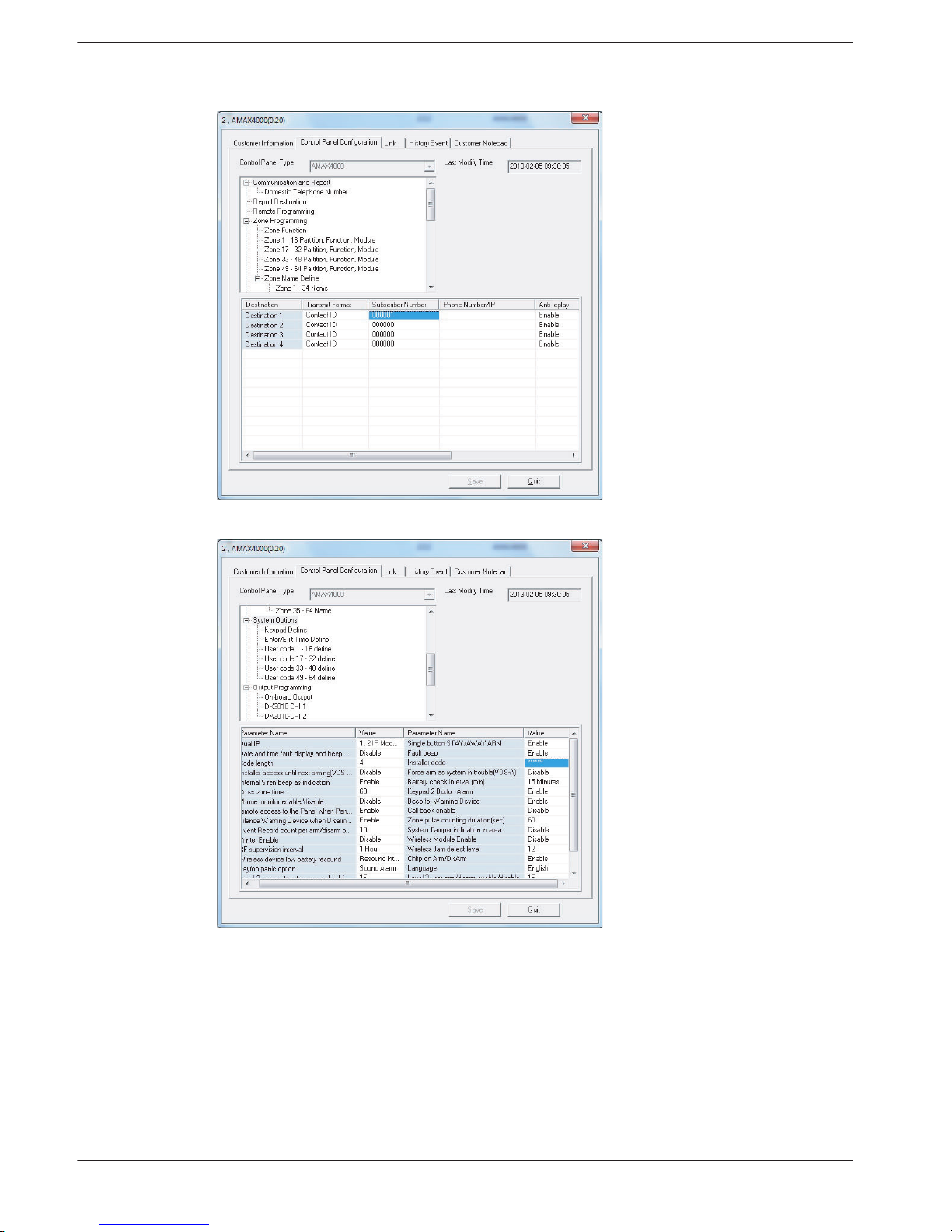
Figure 8.9: AMAX panel configuration- Destination
Figure 8.10: AMAX panel configuration - System options
See also
– AMAX panel configuration- Destination, page 86
Direct Connection
The direct connection function allows establishing a connection from the remote PC to the
AMAX panel via USB cable.
Plug cable into USB port of AMAX panel and connect the other side of this cable to an USB
port of the PC running A-Link Plus software.
8.2.1
86 en | Configuration
AMAX panel 4000 / AMAX panel 4000
EN
2014.4 | 01 | F.01U.267.112 Installation Guide Bosch Sicherheitssysteme GmbH
Page 87
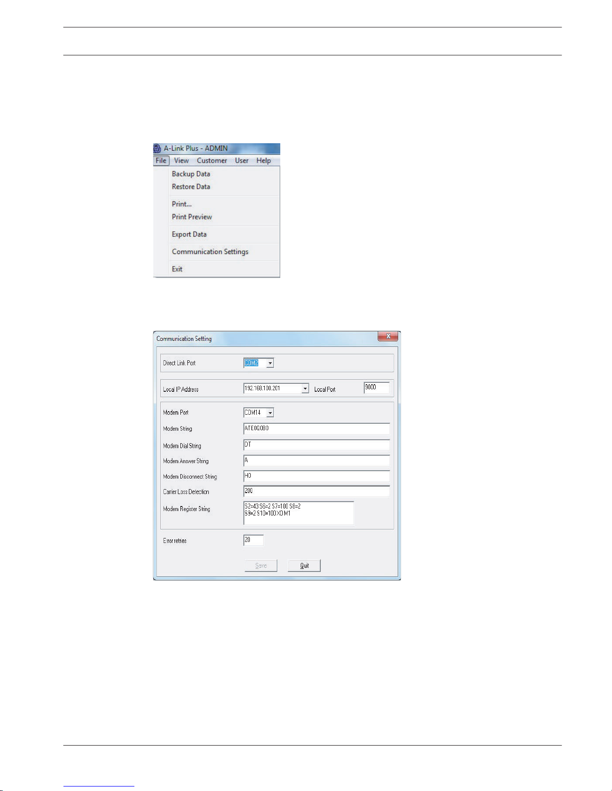
Install USB driver. The device driver is located in A-Link plus application path (example: C\
\program files (x86)\Bosch Security System\A-Link Plus\USB_DRIVER).This installation will
create an additional COM device on the PC. When finished installation, identify the COM-Port
associated to this device.
Select M = menu item file – communication settings.
Figure 8.11: A-Link Plus
Make sure that value for direct link port is the same as the port created by USB driver
installation.
Figure 8.12: Direct link port
Open customer account the AMAX panel. Select index sheet “Link”. Select communication
model “Direct Connect”.
Click on Button “Connect” in order to connect to the AMAX panel.
AMAX panel 4000 / AMAX panel 4000
EN
Configuration | en 87
Bosch Sicherheitssysteme GmbH Installation Guide 2014.4 | 01 | F.01U.267.112
Page 88
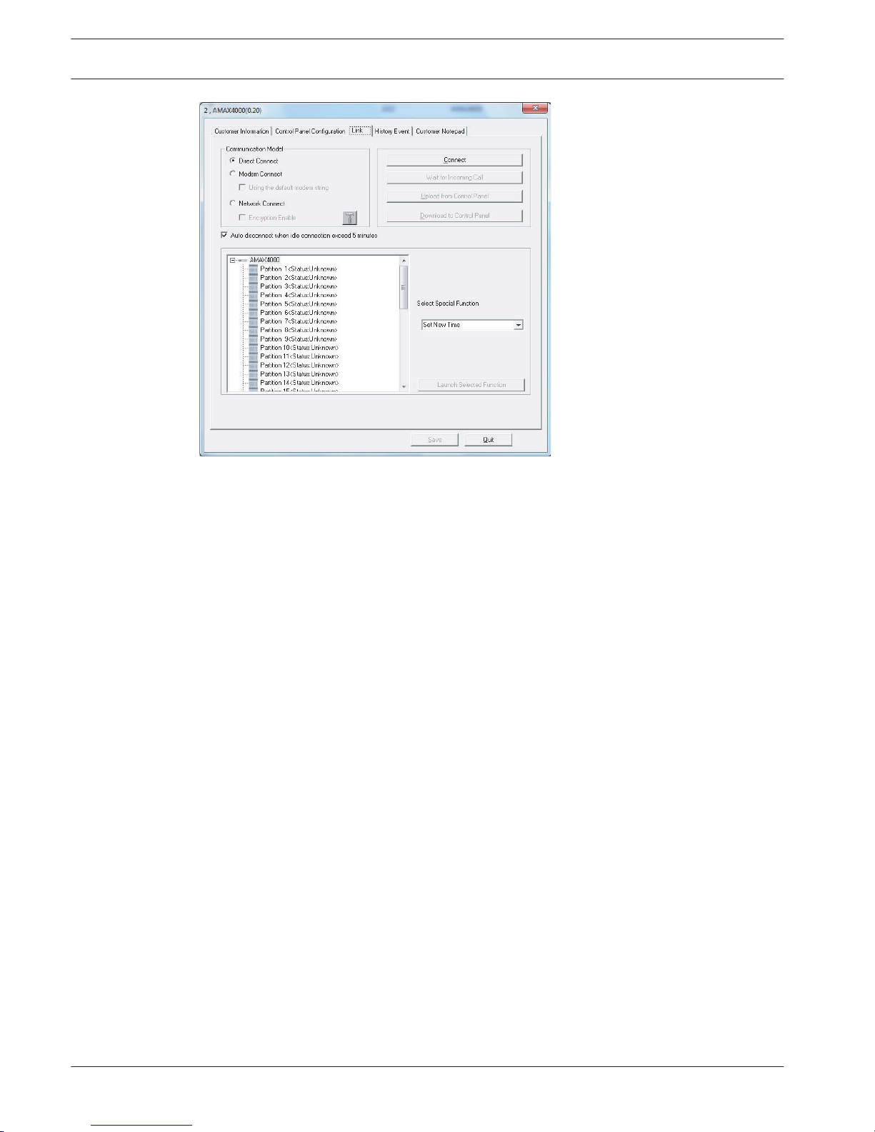
Figure 8.13: Link-Direct Connect
When connected to the AMAX panel, button label changes to “Disconnect”.
Modem Connection
Telephone Remote Connection
The telephone remote connection function allows establishing a connection from the remote
PC to the AMAX panel through telephone network.
1. Number of rings (address 0144), callback telephone number (address 0146 - 0161), and
telephone remote connection enabled (address 0145) are set on the AMAX panel.
2. Run RPS on the remote PC and set relevant parameters in relevant operating interfaces.
– Go to “File” and click “Communication Settings” to set parameters related to modem in
the communication Settings tab page, then click “Save”
8.2.2
88 en | Configuration
AMAX panel 4000 / AMAX panel 4000
EN
2014.4 | 01 | F.01U.267.112 Installation Guide Bosch Sicherheitssysteme GmbH
Page 89
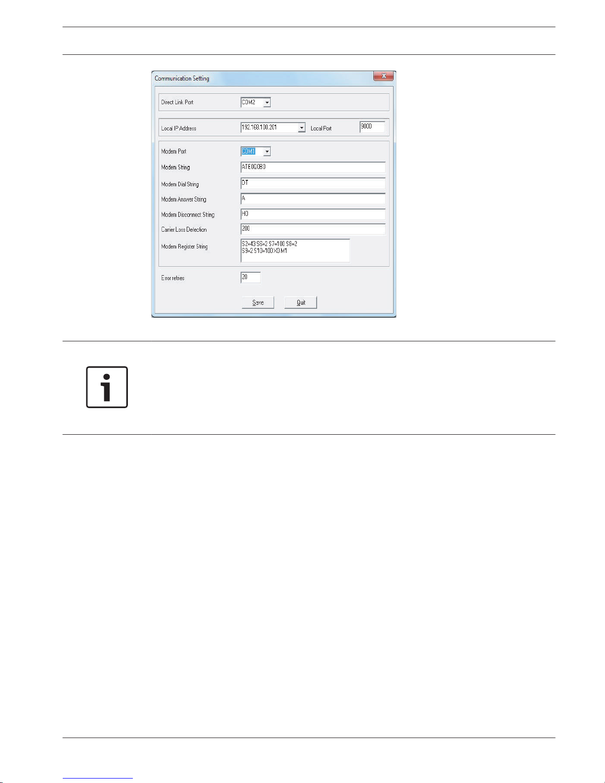
Figure 8.14: Communication Settings
Notice!
Modem string settings in figure x.1 are only used, when the default modem string is not used.
If the default modem string should be used, activate parameter “Using the default modem
string” in register “Link” of Customer Information (see figure x.2). In this case the values in
figure x.1 are ignored.
Instead the following string is used: AT&CI&D2X0&Q0S7=255S9=0+MS=B103B17
– Click “New Customer” in “Customer” to create customer. Enter relevant customer
information in the “Customer Information” tab page. The “Customer Number” must be
entered. Enter the telephone number connected to the AMAX panel in “AMAX Panel
Telephone Number”. The AMAX panel telephone number does not need to be set for
manual connection.
AMAX panel 4000 / AMAX panel 4000
EN
Configuration | en 89
Bosch Sicherheitssysteme GmbH Installation Guide 2014.4 | 01 | F.01U.267.112
Page 90
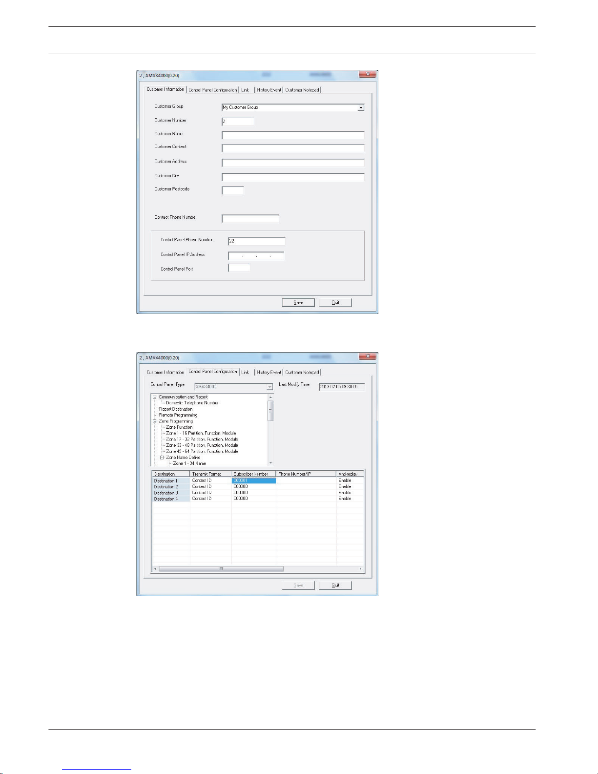
Figure 8.15: Customer Information
Figure 8.16: AMAX Panel Configuration
1. Connect
– Automatic dialing connection: Select “Modem Connect” in the “Link” tab page and click
“Connect”.
– Or manual dialing connection: Select “Modem Connect” in the “Link” tab page and click
“Wait for Incoming Call”, then initiate callback call from the AMAX panel with keypad:
Enter SUBSCRIBER NUMBER, press [5] [7], and then [#].
90
en | Configuration
AMAX panel 4000 / AMAX panel 4000
EN
2014.4 | 01 | F.01U.267.112 Installation Guide Bosch Sicherheitssysteme GmbH
Page 91
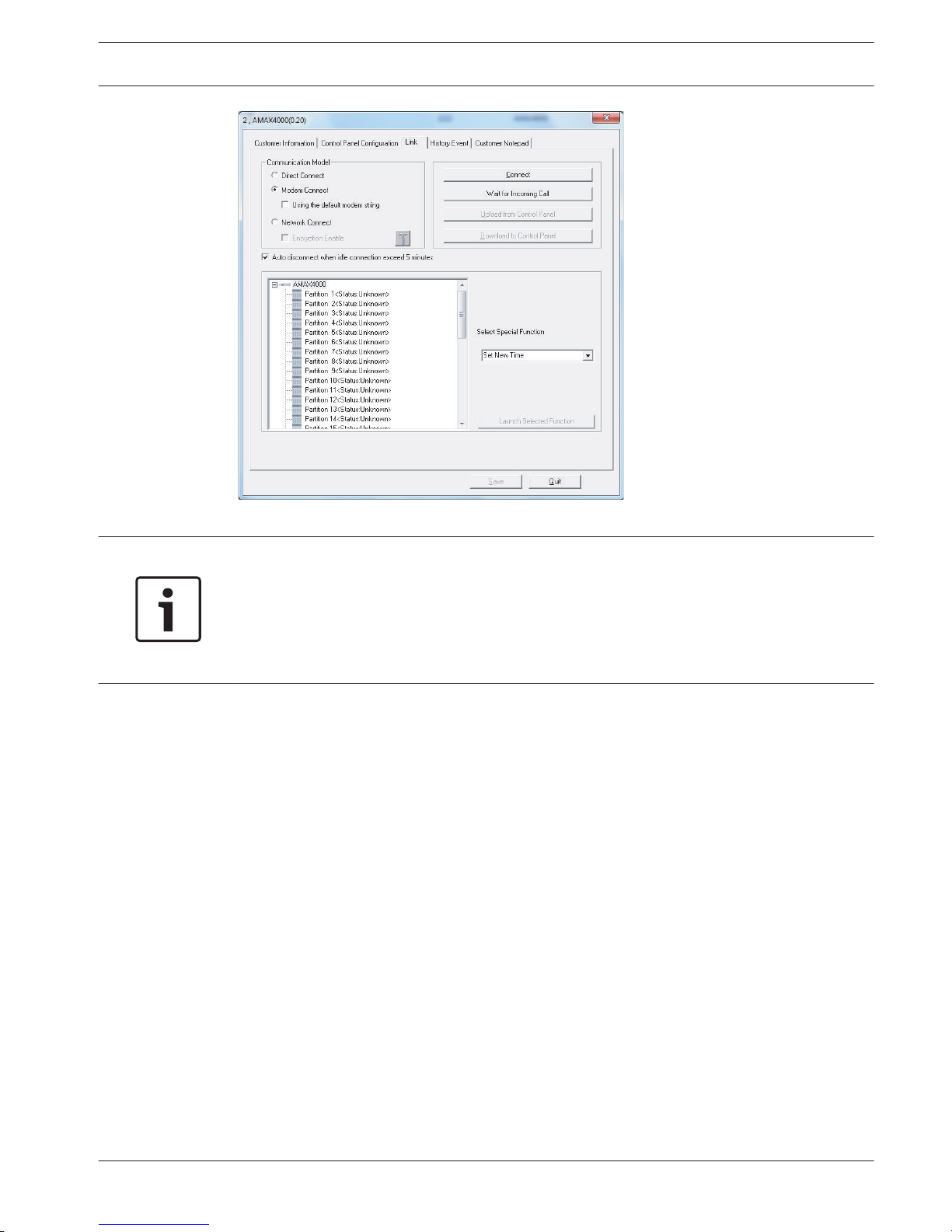
Figure 8.17: Modem Connect
Notice!
Modem string settings in figure x.1 are only used, when the default modem string is not used.
If the default modem string should be used, activate parameter “Using the default modem
string” in register “Link” of Customer Information (see figure x.2). In this case the values in
figure x.1 are ignored.
Instead the following string is used: AT&CI&D2X0&Q0S7=255S9=0+MS=B103B17
After successfully connected, RPS can execute multiple operations, including reading/writing
AMAX panel parameters, remote arming/disarming, viewing log, and so on. After the telephone
is successfully connected, RPS will disconnect it with the AMAX panel after 5 minutes of
idling.
IP Connection
IP Remote Connection
The IP remote connection function allows to establish a connection from the remote PC to the
AMAX panel through LAN or WAN. The remote monitoring center should be installed remote
programming software like A-Link Plus and perform related IP address, programming in order
to apply this function in LAN (support DHCP) and WAN.
The IP remote connection is divided into automatic connection and manual connection with
callback confirmation.
For more information about IP programming, see Remote PC settings
1. Set receiver 1 SUBSCRIBER NUMBER (addresses 0017 - 0022), network remote settings
programming option (addresses 0162 - 0179), i.e., enter IP address, port number of RPS,
and DHCP update time on the AMAX panel.
2. Run RPS on the remote PC and set relevant parameters in relevant operating interfaces.
8.2.3
AMAX panel 4000 / AMAX panel 4000
EN
Configuration | en 91
Bosch Sicherheitssysteme GmbH Installation Guide 2014.4 | 01 | F.01U.267.112
Page 92
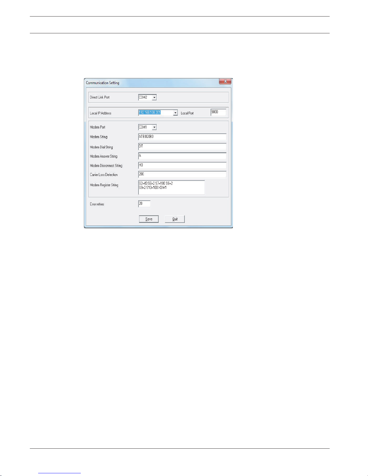
– a. Go to “File” and click “Communication Settings” to select “local IP address” in the
“Communication Settings” tab page. If there are multiple IP addressed in the pull-down
menu, be sure to select the latest local IP address and enter the local port, i.e., the RPC
port number of programming option 0174 – 0178, then click “Save”.
Figure 8.18: Communication Setting
– b. To create customer, click “New Customer” in “Customer”. Enter relevant customer
information in the “Customer Information” tab page. The “Customer Number” must be
entered. The IP address and port number of the AMAX panel are the IP address and port
number of the communication module 1 installed in the AMAX panel, and will be used
when the AMAX panel uses fixed IP and port number. If the fixed IP address and port
number are not known, after the UDP data packet transmitted by the AMAX panel is
received and the SUBSCRIBER NUMBER of receiver 1 has been set in the “AMAX Panel
Configuration” tab page, please directly click the connection in the “connection” tab
page. The prompt information will recommend the SUBSCRIBER NUMBER, the AMAX
panel received the last time IP address and port number..
Under DHCP environment, it is not necessary to set “AMAX Panel IP Address” and “AMAX
Panel Port Number”.
92
en | Configuration
AMAX panel 4000 / AMAX panel 4000
EN
2014.4 | 01 | F.01U.267.112 Installation Guide Bosch Sicherheitssysteme GmbH
Page 93
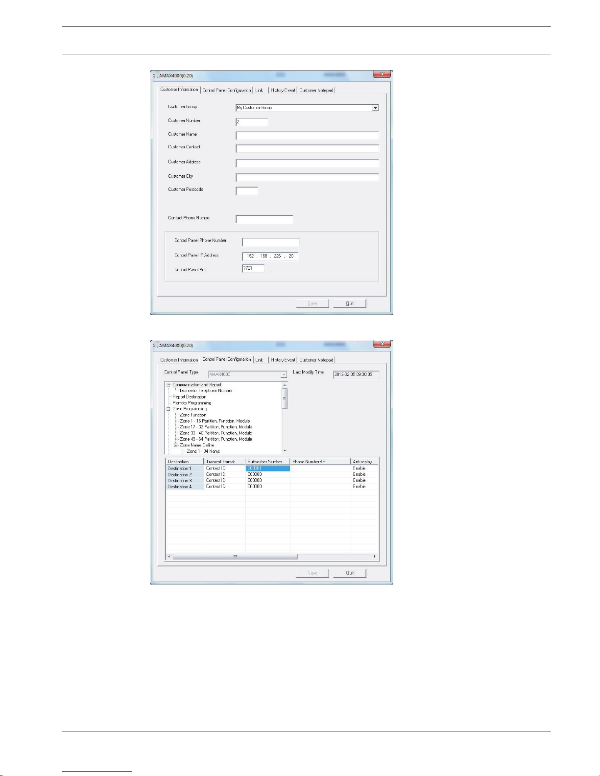
Figure 8.19: Customer Information
Figure 8.20: AMAX Panel Type
1. Connect
– Automatic IP connection: Select “Network Connection” and click “Connect” in the “Link”
tab page.
– Or manual IP connection: Select “Network Connection” and click “Wait for Incoming Call”
in the “Link” tab page. Then initiate IP connection from the AMAX panel with keypad:
Enter SUBSCRIBER NUMBER, press [5] [7], and then [#].
AMAX panel 4000 / AMAX panel 4000
EN
Configuration | en 93
Bosch Sicherheitssysteme GmbH Installation Guide 2014.4 | 01 | F.01U.267.112
Page 94
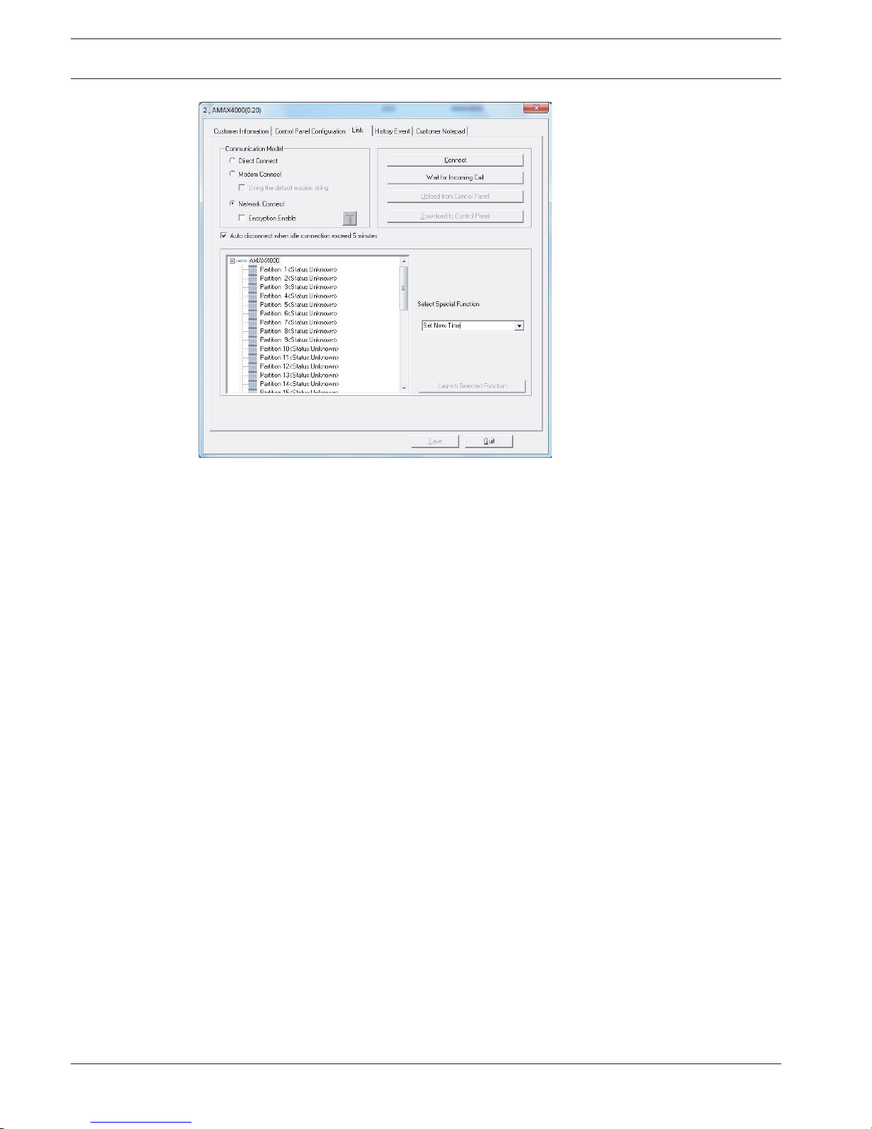
Figure 8.21: Network Connect
After successfully connected, RPS can execute multiple operations, including reading/writing
AMAX panel parameters, remote arming/disarming, viewing log, and so on.
After IP successfully connected, RPS will disconnect it with the AMAX panel after 5 minutes of
idling if you select “Auto disconnect when idle connection exceeds 5 minutes” option.
94
en | Configuration
AMAX panel 4000 / AMAX panel 4000
EN
2014.4 | 01 | F.01U.267.112 Installation Guide Bosch Sicherheitssysteme GmbH
Page 95
Address Programming
The control panel programming options are stored in a non-volatile flash memory. This
memory has all relevant configuration and user-specific data even after a total power loss.
Because the data retention time is quite long without power, reprogramming is not required
after powering up the control panel.
Programming with keypad is possible only when all of zones in the system are in disarmed
status and no alarm is activated. Installer Code is required for programming.
Notice!
It is not recommended to use other keypads or methods simultaneously to program the
system while programming with the current keypad.
Communication and Reports Setting
Report options Address Default
Telephone number / IP address and port for receiver 1 0000 - 0016 15
Subscriber ID number (0 – 9, B – F) 0017 - 0022 000000
Transmission format for receiver (0 = not used, 1 =
contact ID, 2= SIA, 3 = Conettix IP)
0023 1
Anti-replay for receiver (0 = disabled, 1 = enabled) 0024 1
EN=1
Acknowledge wait time for receiver (05 - 99 seconds ) 0025 - 0026 05
Network polling time for receiver (001 - 999 minutes ) 0027 - 0029 001
Telephone number / IP address and port for receiver 2 0030 - 0046 15
Subscriber ID number (0 – 9, B – F) 0047 - 0052 000000
Transmission format for receiver (0 = not used, 1 =
contact ID, 2= SIA, 3 = Conettix IP)
0053 1
Anti-replay for receiver (0 = disabled, 1 = enabled) 0054 1
EN=1
Acknowledge wait time for receiver (05 - 99 seconds ) 0055 - 0056 05
Network polling time for receiver (001 - 999 minutes ) 0057 - 0059 001
Telephone number / IP address and port for receiver 3 0060 - 0076 15
Subscriber ID number (0 – 9, B – F) 0077 - 0082 000000
Transmission format for receiver (0 = not used, 1 =
contact ID, 2= SIA, 3 = Conettix IP)
0083 1
Anti-replay for receiver (0 = disabled, 1 = enabled) 0084 1
EN=1
Acknowledge wait time for receiver (05 - 99 seconds ) 0085 - 086 05
Network polling time for receiver (001 - 999 minutes ) 0087 - 089 001
Telephone number / IP address and port for receiver 4 0090 - 0106 15
Subscriber ID number (0 – 9, B – F) 0107 - 0112 000000
9
9.1
AMAX panel 4000 / AMAX panel 4000
EN
Address Programming | en 95
Bosch Sicherheitssysteme GmbH Installation Guide 2014.4 | 01 | F.01U.267.112
Page 96
Transmission format for receiver (0 = not used, 1 =
contact ID, 2= SIA, 3 = Conettix IP)
0113 1
Anti-replay for receiver (0 = disabled, 1 = enabled) 0114 1
EN=1
Acknowledge wait time for receiver (05 - 99 seconds ) 0115 - 0116 05
Network polling time for receiver (001 - 999 minutes ) 0117 - 0119 001
Notice!
Enter telephone number when the Contact ID or SIA is selected. Enter IP address and port
number when the Conettix IP is selected. Anti-replay for Receiver, Acknowledge Wait Time for
Receiver, and Network Polling Time for Receiver are valid only when using Conettix IP.
Setting telephone number
For telephone number programming, See Telephone Programming Parameters
Setting IP address and port number
The IP address is programmed with the 17 digits: Digits 1 - 12 for the IP address of the
receiver and 13 - 17 for the port.
It is not necessary to enter dots in programming, but 0 must be entered ahead of the digit to
make up 3 digits when each IP address unit is fewer than 3 digits. 0 must be entered ahead of
the digit to make up 5 digits when the port is fewer than 5 digits.
Example:
Receiver IP address 128.73.168.7, port 7700, should be made as: 128 073 168 007 07700
Dual IP Settings
Option
Address Default
0 = 1 IP module, 1 = 2 IP modules 0120 1
Notice!
Dual IP settings are valid only when used in the Conettix IP format. This programming option
is valid for B426 and ITS-DX4020-G modules. ITS-DX4020-G cannot be set as No. 2 IP module.
Module Address
ITS-DX4020-G module or B426- module 1 134
B426 module 2 250
System Reporting
Option Address Default
Zone status restore report 0121 6
AWAY arming / disarming report 0122 6
EN=1/5/6/7
STAY arming / disarming report 0123 6
EN=1/5/6/7
96 en | Address Programming
AMAX panel 4000 / AMAX panel 4000
EN
2014.4 | 01 | F.01U.267.112 Installation Guide Bosch Sicherheitssysteme GmbH
Page 97
System status report (zone fail, comm. fail, telephone line
fail, AC fail, low battery and so on.)
0124 6
EN=1/5/6/7
Keypad panic alarm report 0125 0
Keypad fire alarm report 0126 0
Keypad medical alarm report 0127 0
Automatic test report 0128 6
EN=1/5/6/7
0 = no report, 1 = receiver 1, 2 = receiver 2, 3 = receiver 3, 4 = receiver 4, 5 = receiver 1,2,3,
and 4, 6 = receiver 1 (2,3, and 4 for backup), 7 = receiver 1 (2 for backup) and receiver 3 (4
for backup)
Notice!
When the transmission format for receiver in the receiver programming is set to 0 (not used),
i.e., setting the report option as sending report to a receiver, then the AMAX panel will
actually not send any report.
Automatic Test Report
Address 0129 - 0134 Address Default
Test report time: interval
00 = Do not use timing report , 01 - 99 = 1 - 99 hours
0129 - 0130 24
VDS-A
EN=1-24
Report time: hour
00 - 23 = 0 - 23 hours, others = do not use real-time report
0131 - 0132 99
Report time: minute
00 - 59 = 0 - 59 minutes, others = do not use real-time
report
0133 - 0134 99
Report Expiry Time
Address 0135 - 0137
Address Default
000 = no time limit, 001 - 255 = 1 - 255 minutes 0135 - 0137 000
VDS-A
EN=000
Installer Access Until Next Arming
Address 0138
Address Default
0 = disabled, 1 = enabled 0138 0
VDS-A=1
Force Arm When System Is In Trouble Condition
Address 0139
Address Default
0 = disabled, 1 = enabled 139 1
VDS-A EN=0
AMAX panel 4000 / AMAX panel 4000
EN
Address Programming | en 97
Bosch Sicherheitssysteme GmbH Installation Guide 2014.4 | 01 | F.01U.267.112
Page 98
Siren / PO 1+2 Supervision
Address 0140 Address Default
0 = disabled, 1 = PO1 enabled, 2 = PO2 enabled, 3 =
PO1+2 enabled
0140 0
VDS-A EN=3
Keypad 2 Button Alarm
Address 0141 Address Default
0 = disabled, 1 = enabled 0141 0
Phone Line Monitor
Address 0142
Address Default
0 = disabled, 1 = enabled 0142 0
VDS-A EN=1
Beep For Warning Devices
Address 0143
Address Default
0 = disabled, 1 = enabled 0143 1
Ring Count
Address 0144
Address Default
1 - 13 = Number of rings until the AMAX panel responds
14 = Call the AMAX panel and allow the phone to ring not
more than twice and hang up. Wait a minimum of 8 sec
and call the AMAX panel again. The AMAX panel answers
on the first ring.
15 = Call the AMAX panel and allow the phone to ring no
more than four times and then hang up. If you call again
within 45 sec, the AMAX panel answers the call on the
first ring.
0 = Panel does not answer
0144 14
Remote Programming
Address 0145
Address Default
0 = disabled, 1 = enabled 0145 1
VDS-A=0
Callback Telephone Number
Address
0146 - 0161 Address Default
See Telephone Programming Parameters 0146 - 0161 15
98
en | Address Programming
AMAX panel 4000 / AMAX panel 4000
EN
2014.4 | 01 | F.01U.267.112 Installation Guide Bosch Sicherheitssysteme GmbH
Page 99
Remote PC Setting
Address 0162 - 0179 Address Default
RPC IP no 0162 - 0173 15
RPC port number 0174 - 0178 15
AMAX panel DHCP update time (hours) 0179 15
RPC is a remote programming computer equipped with remote programming software.
Remote Access To Panel When Panel Is Armed
Address 0180 Address Default
0 = disable, 1 = enable ; default 1 0180 1
Keypad Language
Address 0181
Address Default
0 = default, 1 = EN, 2 = DE, 3 = ES, 4 = FR, 5 = IT, 6 = PL, 7
= NL, 8 = SE
0181 0
Tamper Reset For User
Address 0182
Address Default
0 = disable, 1 = enable 0182 1
Arm / Disarm For Installer
Address 0183
Address Default
0 = disable, 1 = enable 0183 0
Zone Tamper Bypass when DEOL Zone is Bypassed
Address 0184
Address Default
0 = disable, 1 = enable 0184 1
0=Incert
– This function is only accessible in address programming
Onboard Tamper Reaction Time
Address
0185 Address Default
0 = 400 ms, 1 = 150 ms 0185 0
1=Incert
– This function is only accessible in address programming
AMAX panel 4000 / AMAX panel 4000
EN
Address Programming | en 99
Bosch Sicherheitssysteme GmbH Installation Guide 2014.4 | 01 | F.01U.267.112
Page 100
Call Back Setting
Address 0196 Address Default
0 = disable, 1 = enable 0196 0
Silence Warning Device When Disarmed
Address 0197 Address Default
0 = disable, 1 = enable 0197 1
Zone Pulse Count Duration
Address 0198 - 0200
Address Default
0 = disable, 1 - 999sec = duration 0198 060
VDS-A
EN=000
Event Record Count per Set/Unset Period
Address 0201
Address Default
3 - 10 0201 10
EN=10
System Tamper Indication In Area
Address 0202
Address Default
0 = area 1, 1 = all areas 0202 0
Internal Siren Beep As Indication
Address 0203
Address Default
0=Disable, 1=enabled 0203 0
Battery Check Interval
Address 0204
Address Default
0 = disabled , 1-15 minutes 0204 15
VDS-A
EN=15
Cross Zone Timer
Address
0205 - 0207 Address Default
001 - 999 sec 0205 - 0207 060
100
en | Address Programming
AMAX panel 4000 / AMAX panel 4000
EN
2014.4 | 01 | F.01U.267.112 Installation Guide Bosch Sicherheitssysteme GmbH
 Loading...