

Bosch ICP-AMAX4-P2-EN, ICP-AMAX4-P3-EN, ICP-AMAX4-P1, AMAX panel 4000, AMAX panel 4000 EN Quick Start Manual
AMAX panel 4000 / AMAX panel 4000 EN
ICP-AMAX4-P1 / ICP-AMAX4-P2-EN / ICP-AMAX4-P3-EN
en Quick Start Guide


Table of contents
1
Short information 4
2
System overview 5
3
Installation 7
3.1 System Power Up 7
3.2 System Status Indicator 7
3.3 Installer and User Code Commands 7
3.4 Prerequisites for Certification conform Installation 9
4
Configuration 10
4.1 Programming with Keypad 10
4.1.1 LCD Keypad Menu Programming 10
4.1.2 LED/Icon LCD Keypad Address Programming 10
4.2 Reset to Factory Default Settings 11
4.3 LCD Menu Programming 12
4.4 Address Programming 20
4.4.1 Communication and Report Setting 20
4.4.2 Zone Programming 26
4.4.3 Output Programming 38
4.4.4 Access Codes 43
4.4.5 System Programming 49
5
Troubleshooting 63
6
Technical Data 66
AMAX panel 4000 / AMAX panel 4000
EN
Table of Contents | en 3
Bosch Sicherheitssysteme GmbH Quick Start Guide 2013.07 | 03 | F.01U.267.113

Short information
Thank you for choosing the AMAX panel 4000. This is a flexible, reliable, convenient, and easyto-use alarm system. It has 16 wired zones on board, expandable up to 64 wired and wireless
zones.
This Quick start guide is provided with the system to give basic information about the system
wiring, components, and describe how to simply program and operate the system with IUIAMAX4-TEXT keypad, IUI-AMAX3-LED16 keypad, IUI-AMAX3-LED8 keypad, ICPKP8-LED keypad,
or ICP-KP8L-Icon LCD keypad. As the system includes a large number of programmable
functions and options, we suggest reading the complete installation manual. For detailed
operation method, please refer to the User Guide.
1
4 en | Short information
AMAX panel 4000 / AMAX panel 4000
EN
2013.07 | 03 | F.01U.267.113 Quick Start Guide Bosch Sicherheitssysteme GmbH

System overview
Information:
Customer:
Location:
Account #:
Installe r:
Date:
2
AMAX panel 4000 / AMAX panel 4000
EN
System overview | en 5
Bosch Sicherheitssysteme GmbH Quick Start Guide 2013.07 | 03 | F.01U.267.113
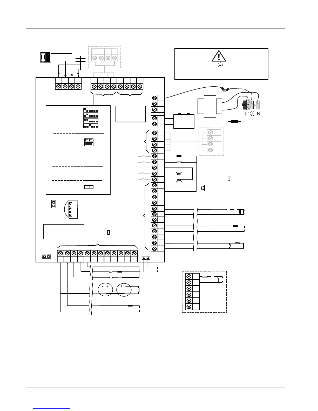
Wiring Diagram
Pro
gram Key Port
GND
-
+
A C
A
C
Transformer
Battery
Tam
per
L2 COM
COM
COM
L1a
L3
L4
L5
L6
L7
L8
L9
COM
COM
COM
COM
L10
L11
L12
L13
L14
L15
L16
P0+4
R
B
G
Y
AUX1
-
AUX2
-
AUX1
+12V
Y
G
B
R
RINGRHTHTIP
L1b
P0+3
P0+
P0-2
P0-1
Zones
Bosch Option
Bus 2 < 900mA
+12V
+
0 V
1
2
3
3
1 Tamper Switch
2 Zone Switch
3 EOL 2,2 k
3
2
3
2
Fuse 1 A
PO+4: < 750mA
PO+3: < 750mA
PO -2: < 500mA
PO -1: < 500mA
230V ~50Hz
230mA
Wac
hdog
outpu
t
<100
mA
12V < 18Ah
18VAC@50VA
Zones
AUX 1: < 900mA
AUX 2: < 900mA
AUX Power
Fir
e
Intrusion
Risk of shock if N,L1 or is connected incorrectly.
For operation safety, the ground terminals must
be connected.
3
3
2
Slow flash: Normal state
On: Trouble state
Off: Trouble state
_
_
_
_
_
_
_
_
+12V
+12V
+12V
COM
_
12V 7Ah
AUX2
+12V
_
COM
supervised
PO-5
Z1
2
2
3
3
Keypads:
IUI-AMAX4-TEXT
IUI-AMAX3-LED16
IUI-AMAX3-LED8
Keypads:
IUI-AMAX-LED8
IUI-AMAX-LCD8
I/O Moduls:
DX2010 Adr. 103 - 108
DX3010 Adr. 150 - 151
DX4010 Adr. 253
Communicators:
DX4020G Adr. 134
B426 Adr. 134(6) / 250(9)
RF Receiver:
RF3227E 1=
RFRC-OPT 1= (1)
1 =
2
=
3 =
4
=
1 =
2 =
Bosch Option
Bus
1 < 900
mA
COM
R
B
G
Y
R
B
G
Y
R
B
G
Y
♥
IUI-AMAX3
+4 Keypad
3
1
2
1
Facto
ry
Default
5-16 Inst. Guide
I
2000mA
100 Ω - 2,2 k
_
<
∑
3
6 en | System overview
AMAX panel 4000 / AMAX panel 4000
EN
2013.07 | 03 | F.01U.267.113 Quick Start Guide Bosch Sicherheitssysteme GmbH
Installation
This system / product must be installed by a qualified installer / service person.
During installation and wiring, the control panel power source must be switched-off to prevent
equipment damage.
– To switch off the Power Source, an easy accessible circuit breaker must be available.
– The System / product must be connected to a socket-outlet with a protective earthing
contact
The User has to disconnect all Telecommunication Network Connectors before unplugging the
power adaptor
After the control panel wiring is completed, connect the AC power and backup batteries.
The power light on the keypad will light to show that AC power is connected.
Notice!
- Use only non spillable battery
- Battery must be recycled and disposed of properly
- When battery is not replaced correctly risk of fire explosion or burning
Notice!
The system must be installed and maintained by qualified installer / service person.
Bosch recommends testing the whole alarm system at least once a week.
Maintenance should be done by qualified installer / service person four times a year.
System Power Up
After the system is powered up, set date and time. Otherwise, the system prompts as fault.
After the system is powered up or reset, it resets to previous arming / disarming status.
To reduce false alarms caused by system power-up (or by power supply restoration after both
mains supply and AUX power supply fail), the system is designed to not perform zone test
within one minute after power-up.
System Status Indicator
The system status is indicated by the LED status indicator on the system main board.
Slow flash of red status indicator (repeating on and off with an interval of 1 second) indicates
normal system operation.
Installer and User Code Commands
The system supports programmable 4- to 6-digit Installer and User Code to execute the
following programming and operating commands.
The installer commands can be used only when all areas of the system are in disarming status
with no alarm activated and when installer access is enabled from user.
Notice!
No identical User Codes are allowed. User Codes are not permitted to be the same as
Installer codes.
3
3.1
3.2
3.3
AMAX panel 4000 / AMAX panel 4000
EN
Installation | en 7
Bosch Sicherheitssysteme GmbH Quick Start Guide 2013.07 | 03 | F.01U.267.113

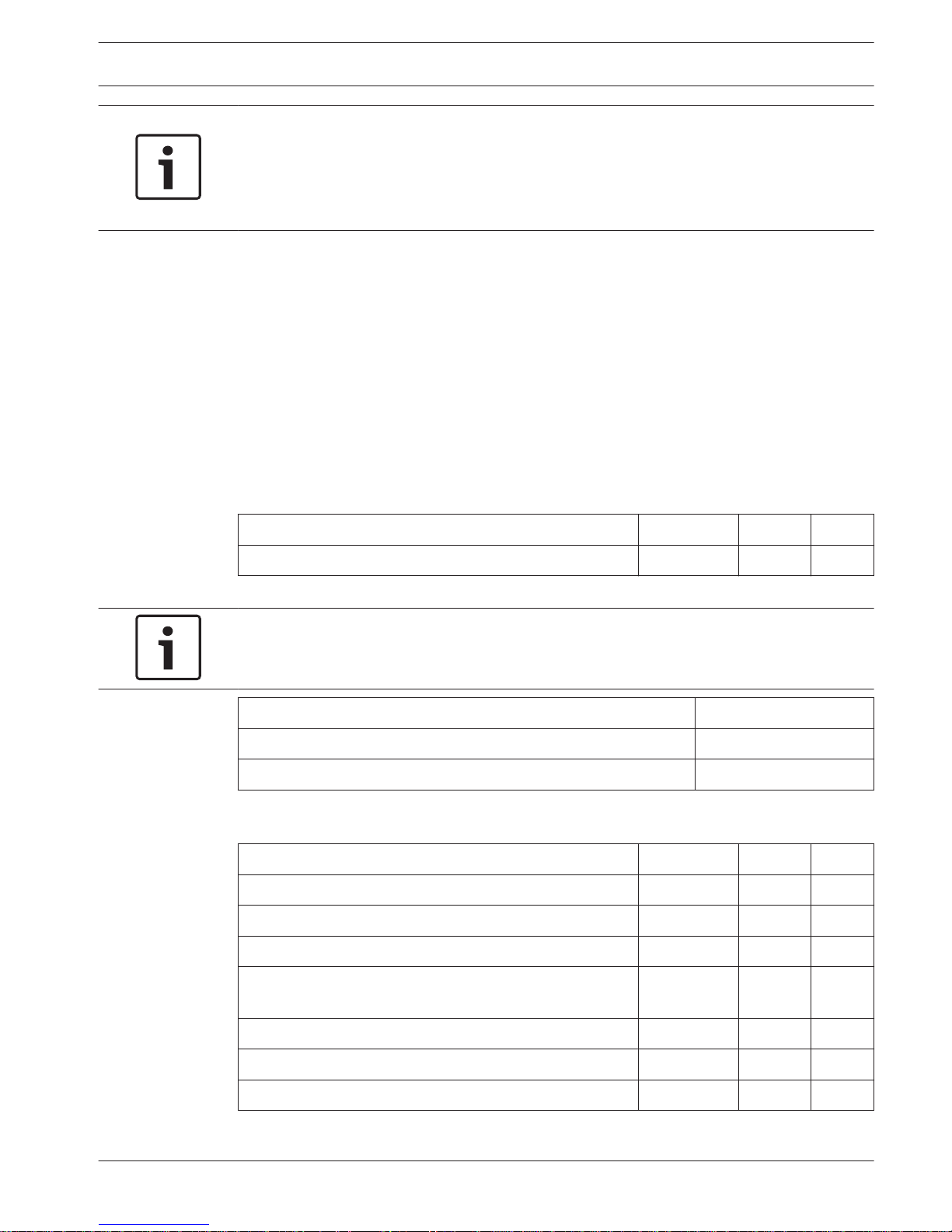
User Code Commands
Function
(Default User Code = 2580
Default Inst. Code = 1234)
Command
Duress User
Arming User
Basic User
Super User
Master User
Instal. User
S witc h to M ai n K ey pa d [C od e] + [ 0][0 ][0 ] + [# ] (T ext KP ) √ √
S witc h to P ar titi on 01 -16 [C od e] + [ 0][ _ ] [ _ ] + [#] (T ext KP ) √ √
A W AY arm [C od e] + [ 1][1 ] + [# ] / [Co de ] + [# ] / [# ] (Q u ick arm ) √ √ √ √ √ √
S TAY a rm [C od e] + [ 1][2 ] + [# ] / [Co de ] + [*] / [* ] (Q ui ck arm ) √ √ √ √ √ √
D isa rm [C od e] + [ #] √ √ √ √ √
D isp lay In fo ( Fa ult /Ta mp er. .) [C od e] + [ -] √ √
Keypad Emergency Alarm
Keypad Fire
Keypad Medical Alarm Long press [7] and [9]
Fa ul t/Ta m pe r In qu ire [C od e] + [ 2][1 ] + [# ] √ √ √
Check All Event Log
[C od e] + [ 2][2 ] + [# ] √ √ √
Check EN Event Log
[C od e] + [ 2][3 ] + [# ] (T ex t K P) √ √ √
Check Dialer Event Log
[C od e] + [ 2][4 ] + [# ] (T ex t K P) √ √ √
Zone Bypass/Cancel
[Code] + [3][1] + [#] + [Zone No] [*] + [#] (Bypass)
√ √ √ √
[Code] + [3][1] + [#] + [Zone No] [*] + [#] (Cancel LED)
√ √ √ √
[Code] + [3][2] + [#] + [Zone No] [*] + [#](Cancel Text KP)
√ √ √ √
Bypass Inquire
[Code] + [3][3] + [#] (Text KP)
√ √ √ √
B ypa ss Fa ult /Ta mp er [C od e] + [ 3][4 ] + [# ] √ √ √ √
S iren te st [C od e] + [ 4][1 ] + [# ] √ √ √
C om mu nic at ion te st [C od e] + [ 4][2 ] + [# ] √ √ √
W al k t est [ Co de ] + [4] [3] + [ #] √ √ √
C han ge /V iew da te /tim e [C od e] + [ 5][1 ] + [# ] √
D ayl igh t S avi ng Tim e (+1 h) [C od e] + [ 5][2 ] + [# ] √ √ √
D ayl igh t S avi ng Tim e (-1 h) [C od e] + [ 5][3 ] + [# ] √ √ √
A dd / D ele te / C ha nge U se r [C od e] + [ 5][4 ] + [# ] √ √
C han ge In div idu al Co de [C od e] + [ 5][5 ] + [# ] √ √ √ √ √ √
C han ge D om es tic Ph on e N o.1
[C od e] + [ 5][6 ][# ] + [ _ _ _ _ _ _ ] [#] (LE D KP ) √
C han ge D om es tic Ph on e N o.2
[C od e] + [ 5][6 ][# ][# ] + [ _ _ _ _ _ _ ] [#] (LE D KP ) √
C han ge D om es tic Ph on e N o.3
[C od e] + [ 5][6 ][# ][# ][# ] + [ _ _ _ _ _ _ ] [#] (LE D KP ) √
C han ge D om es tic Ph on e N o.4
[C od e] + [ 5][6 ][# ][# ][# ][#] + [ _ _ _ _ _ _ ][ #] ( LE D K P ) √
C han ge D om es tic Ph on e N o.1 -4 [C ode ] + [5 ][6 ][# ] + [_] + [ #] + [ _ _ _ _ _ _ ][# ] (T ex t K P) √
C all Ba ck [C od e] + [ 5][7 ] + [# ] √
C han ge La ng ua ge
[C od e] + [ 5][8 ] + [# ] + [ _ ] [ _ ] + [ #]
01 =E N 02 =D E 03 =E S 04 =F R
05 =I T 06 =P L 07 =N L 08 =S E
√ √ √
R ese t t am pe r o r fa ult [C ode ] + [6 ] + [# ] √ √ √
Installer Access
[Code] + [7][1] + [#] (Enable)
[Code] + [7][2] + [#] (Disable)
√
S yst em re set [C od e] + [ 9][9 ][8 ][9 ] + [#] √ √ √
In sta lle r p rog ram m od e [C od e] + [ 9][ 5][ 8] + [# ] √
E xits Pr og r. m od e with ou t s av e [9 ][5 ][9] + [#]
(o nly in Ad re ss Pro gr. M ode )
√
E xits Pr og r. m od e with s ave [ 9][ 6][0 ] + [# ]
(o nly in Ad res s P ro gr. Mo de )
√
S et F ac tor y D ef aul ts [9 ][6 ][1] + [#]
(o nly in Ad re ss Pro gr. M ode )
√
C opy co nt rol pa ne l da ta to pro gr . K ey [9 ][6 ][2] + [#]
(o nly in Ad re ss Pro gr. M ode )
√
C opy p rog r. k ey da ta to con tro l p an el. [ 9][ 6][3 ] + [# ]
(o nly in Ad res s P ro gr. Mo de )
√
D isp lay FW ver sio n [9 ][9 ][9] + [#]
(on ly in A dr ess P rog r. M od e)
√
Long press [1] and [3] or [*] and [#]
Long press [4] and [6]
Figure 3.1: User Code Commands
8 en | Installation
AMAX panel 4000 / AMAX panel 4000
EN
2013.07 | 03 | F.01U.267.113 Quick Start Guide Bosch Sicherheitssysteme GmbH

Prerequisites for Certification conform Installation
EN 50131-3 Grade 2, Environmental Class 2
– System must be placed inside the monitored area on a stable surface.
– Keypads must be mounted to the inner side of the monitored area.
– Once the system is tested and ready to use, Enclosure Door and Accessory Enclosures
must be secured with the provided screws
– To realize EN conform Alarm Indication and Transmission, one of the following options
must be used
– Two supervised Warning devices (PO-1 PO-2 & PO+) and one ATS 2 Communicator
(onboard Dialer, B426, D4020 or DX4020G)
– One self powered Warning Device and one ATS 2 Communicator (onboard Dialer,
B426, D4020 or DX4020G)
– Two Communicators, one ATS 2 (onboard Dialer, B426, D4020 or DX4020G) and one
ATS 1 (onboard Dialer, B426, D4020 or DX4020G)
– One ATS 3 Communicator (DX4020 or B426)
All Communicators must be connected to a Central Monitoring Station.
Only the onboard Dialer and the Option Bus Communicators can be used for EN Alarm
Transmission.
– one 12V/7AH or one 12V/18Ah Battery must be connected to the System.
– max current for all components with a 7Ah Battery = 550mA
max current for all components with a 18Ah Battery = 1500mA
(standby 12h, recharge Battery 80% in 72h)
(PCB=l00mA, IUI-AMAX Keypads=31mA, DX2010=35mA, DX3010=10mA, B426=100mA,
DX4020G=65mA, RF3227E=30mA, RFRC-OPT=30mA)
– To realize EN conform Arming procedure an indication of arm/disarm status must be
accessible from outside the monitored area (this indication can be time limited)
– To realize EN conform Access to the Monitored Area, one of the following options must
be used
– Opening a door (to the entry/exit route) must start the entry procedure
– Indication of arm/disarm Status
– Access to the monitored Area (doors not starting entry procedure) is prevented (e.g.
door strike, mechanically)
The Enclosure lock can only be used in non EN setup.
– Telephone arming can only be used in non EN setup.
– Accessory Modules, except input module (DX2010) can be used only inside the enclosure
(on the adapter plate).
– When input module (DX2010) is used in the external enclosure (AE20) the tamper skirt
must be installed on the PCB of input module (DX2010)
– The panel must be programmed with the EN settings indicated on the programming
sheet. When the panel is set without EN parameters, the EN Indication (on Label) must
be removed.
3.4
AMAX panel 4000 / AMAX panel 4000
EN
Installation | en 9
Bosch Sicherheitssysteme GmbH Quick Start Guide 2013.07 | 03 | F.01U.267.113
Configuration
The control panel programming options are stored in a non-volatile flash memory. This
memory has all relevant configuration and user-specific data even after a total power loss.
Because the data retention time is quite long without power, reprogramming is not required
after powering up the control panel.
Programming with keypad is possible only when all of zones in the system are in disarmed
status and no alarm is activated. Installer Code is required for programming.
Notice!
It is not recommended to use other keypads or methods simultaneously to program the
system while programming with the current keypad.
Programming with Keypad
LCD Keypad Menu Programming
1. Enable Text keypad and confirm that the system is in disarmed status.
2. Enter Installer Code + [958] and press [#] to get to [Installer Menu].
3. Programming: Select the menu and operate according to the menu prompt.
– Down to the next menu: Press [▼]
– Up to the previous menu: Press [▲]
– Enter menu or confirm input: Press [#]
– Back to the menu or delete a single input: Press [-]; or press and hold [-] for 3
seconds to end the input state and get back to the menu.
– Operate according to the menu prompt. Select menu and enter data for specific
programming items according to the display on the keypad to complete
programming, step by step.
– The data value ranges in the menu programming and address programming are the
same. For specific options and value ranges, see contents in LCD Keypad Menu
Programming, page 10.
4. After completing input, press [-] to get back to the previous menu. Complete all
programming input by repeating step 3 and press [-] to get back to the current main
menu level by level.
5. Press [-] to enter menu options. It is optional to save or not to save the programming
information.
6. Select [Save and Exit] and press [#] to save system programming data, exit menu
programming and reset system.
LED/Icon LCD Keypad Address Programming
1. Enable LED keypad or Icon LCD keypad and make sure that the system is in disarmed
status.
2. Enter programming mode: Enter the Installer Code (the default is 1234) + [958] and
press [#].
3. Programming: Move to the required address and enter the value for each data bit (data
value).
– After entering programming mode, the system directly enters the programming data
in the address 0000 (Receiver 1 telephone number or the initial digit of the IP
address), then
4
4.1
4.1.1
4.1.2
10 en | Configuration
AMAX panel 4000 / AMAX panel 4000
EN
2013.07 | 03 | F.01U.267.113 Quick Start Guide Bosch Sicherheitssysteme GmbH
– Enter the next address: Press [#]
– Back to the previous address: Press [*]
– Skip to other address: Enter the address code and press [#]
– Set new data in the address: Enter new data values and press [*]
– Enter new data values as required. Otherwise, the factory Default will be used in the
system.
4. Exit programming mode: Enter Command [9] [6] [0] and press [#] to save programming
data. Entering [9] [5] [9] + [#] means not to save the programming data.
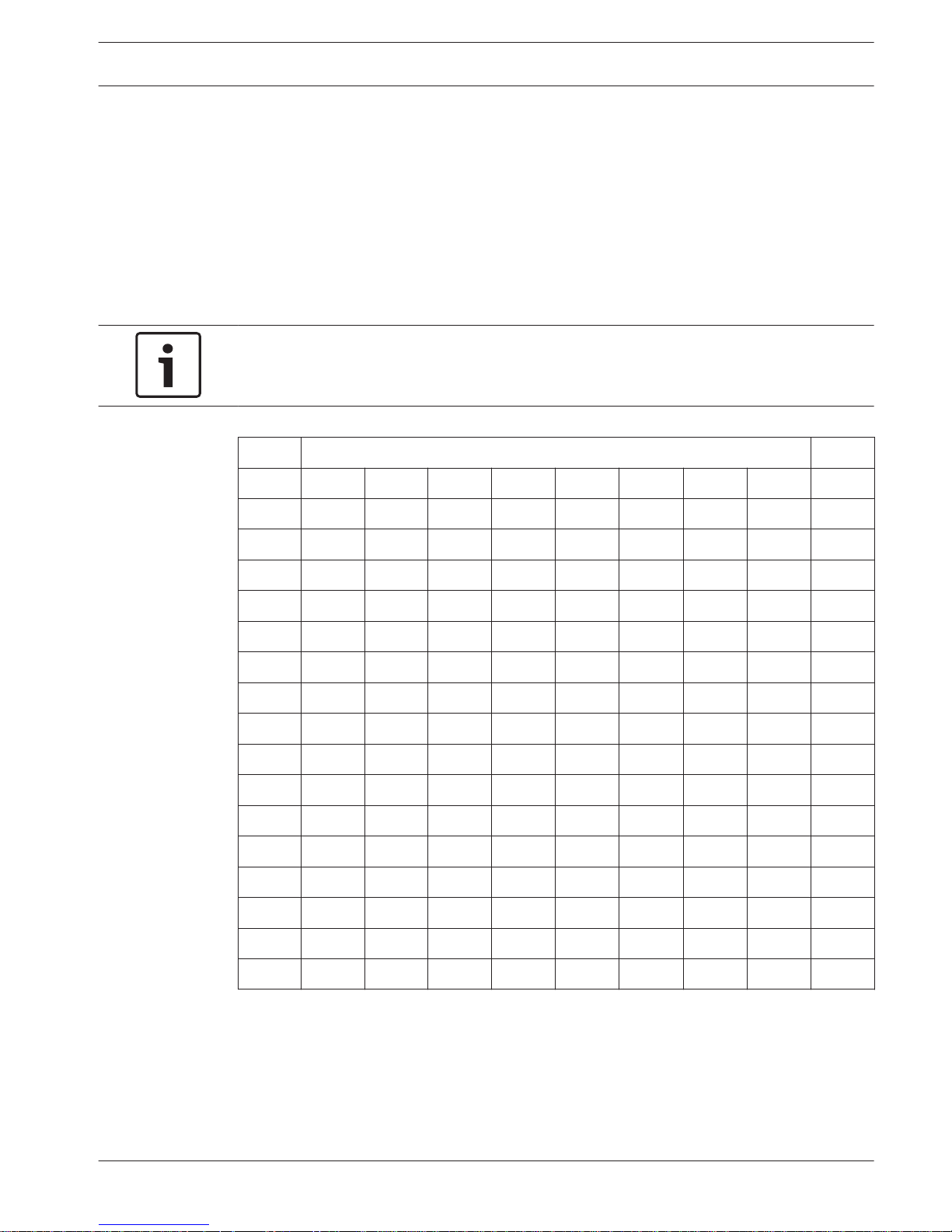
For LED/Icon LCD keypad, the programming data is displayed by the keypad indicator. See
Programming Data Indicators, page 11.
Notice!
For LED/Icon LCD keypad, when the programming data exceeds the display range of the
keypad indicator, there will be no display on the keypad.
Programming Data Indicators
Data Zone Indicators
Value 1 2 3 4 5 6 7 8 Mains
0
1 X
2 X
3 X
4 X
5 X
6 X
7 X
8 X
9 X X
10 X
11 X X
12 X X
13 X X
14 X X
15 X X
Reset to Factory Default Settings
The factory Default can be reset with the ‘Resetting to Factory Default’ pads on the main
board of the control panel.
1. Disconnect the AC power supply and backup battery to the control panel.
2. Short-circuit the ‘Resetting to Factory Default’ pads.
3. These set of pads are located at the top on the printed circuit board of the control panel.
4.2
AMAX panel 4000 / AMAX panel 4000
EN
Configuration | en 11
Bosch Sicherheitssysteme GmbH Quick Start Guide 2013.07 | 03 | F.01U.267.113
4. Powering up is done when the bonding pads are short-circuited.
5. Quick flash of the red LED indicator on the printed circuit board of the control panel
indicates that the factory Default will be reset.
6. All programming parameters are reset to factory default immediately after releasing the
short-circuited bonding pads.
Notice!
If the DEFAULT pads are short-circuited for over 10 seconds after power-up, the control panel
will discard resetting to factory Default.
LCD Menu Programming
For menu programming with LCD keypad, see Section 4.1.1 LCD Keypad Menu Programming
on page 10.
Use [▼] and [▲] to move main menus, submenus and secondary submenus up or down.
Use [-] and [#] to move main menus, submenus and secondary submenus left or right.
4.3
12 en | Configuration
AMAX panel 4000 / AMAX panel 4000
EN
2013.07 | 03 | F.01U.267.113 Quick Start Guide Bosch Sicherheitssysteme GmbH
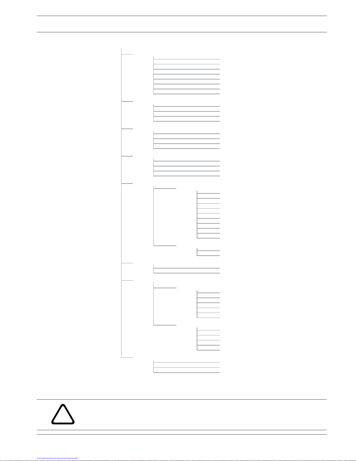
COPY DATA TO KEY
FUNCTION VIEW
FAULT ANALYSIS
RF SETTING
RF RECEIVER
RF SENSOR DIAGNOSE
CLR ALL RF DEVICES
SIREN SETTINGS
ZONE FUNCTION
QUICK ARM ONLY */#
INSTALLER ACCESS
EVENT RECORD COUNT
SYSTEM SETTING
ADD/DELETE ZONE
PULSE COUNT DURAT.
RING TIMES
CODE SETTING
RPC IP/PORT/DHCP
INSTALLER MENU
COM+REPORT SETTING
RECEIVER SETTING
REPORT SETTING
RF LOW BATT REPEAT
SIREN BEEP AR/DIS
ADDRESS PROGRAM
COPY DATA TO PANEL
ADDRESS/KEY PROGR
RF DEVICE MANAGER
RF USER
RF REPEATER DIAGN.
RF REPEATER
RF JAM DETECT LEV.
RF KEYFOB PANIC AL
RF SUPERVISION
OUTPUT SETTINGS
RF PARA. SETTING
FORCE ARM FAULT/TA
FW VERSION
OUTPUT SETTING
SYS TAMPER INDIC.
DATE/TIME
FACTORY DEFAULT
LANGUAGE VERSION
KP 2 BUTTON ALARM
KP TONE/LOCKOUT
FUNCTION SETTING
FAULT CONFIG
KEYPAD AREA
AREA TIMING
COMMON AREA
CROSS TIMER
ZONE SETTING
TEST REPORT DURAT.
DUAL IP
REMOTE ACCESS
DOMESTIC/CALLBACK
INSTALLER CODE
CODE PERMISSIONS
KP/AREA SETTING
CODE LENGTH
USER CODE
Figure 4.1: Menu Structure
!
Warning!
Programming parameters must be set within the value range in the programming address.
Otherwise, the system will turn to indeterminate status.
AMAX panel 4000 / AMAX panel 4000
EN
Configuration | en 13
Bosch Sicherheitssysteme GmbH Quick Start Guide 2013.07 | 03 | F.01U.267.113
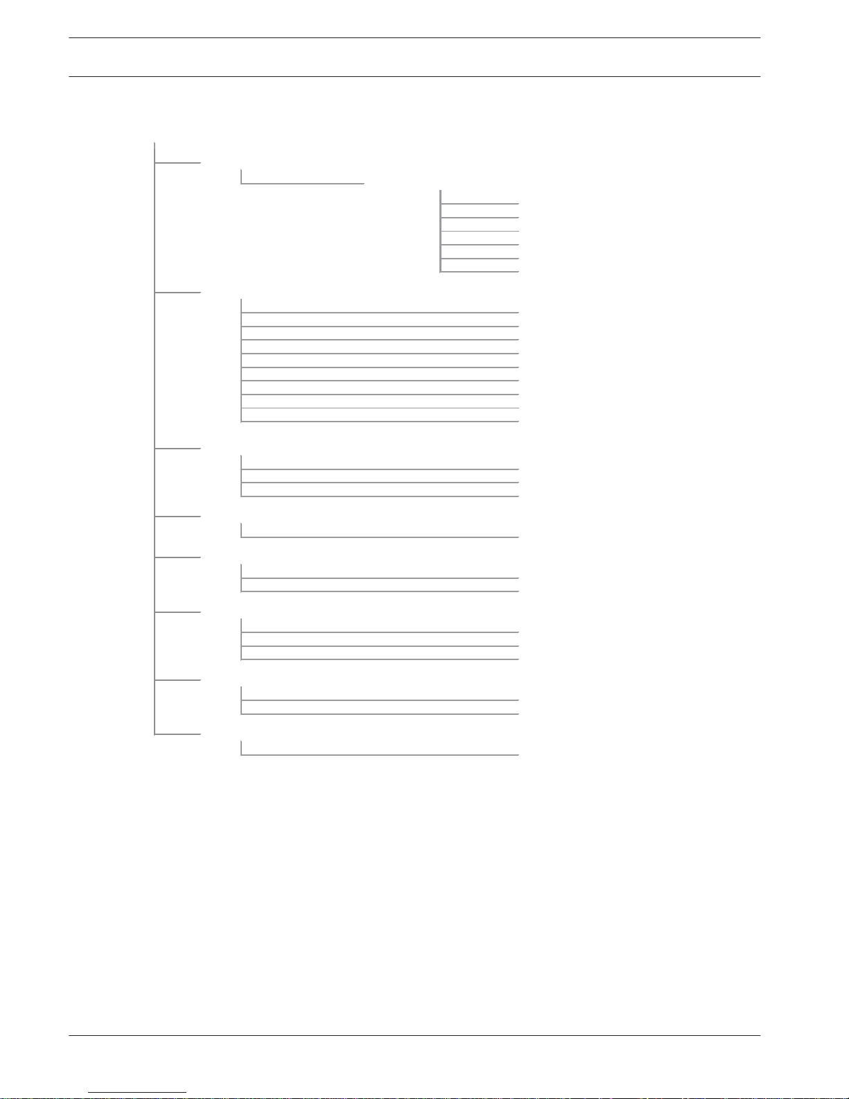
ZN RESTORE REPORT
AWAY REPORT
STAY REPORT
SYSTEM STAT REPORT
PANIC REPORT
FIRE REPORT
MEDICAL REPORT
AUTOM. TEST REPORT
REPORT EXP. TIME:m
TEST RPT INTERV: h
TEST REPORT: hour
AUTOM. TEST REPORT
TEST REPORT DURAT.
DUAL IP SETTING
REM. ACCESS ARMED
REMOTE PROGRAMMING
DUAL IP
REMOTE ACCESS
RPC IP/PORT/DHCP
IP ADDRESS
PORT No
DHCP UPDATE TIME:h
CALLBACK SETTING
DOMEST/CALLBACK No
DOMESTIC/CALLBACK
RING COUNT
RING TIMES
COM+REPORT SETTING
RECEIVER SETTING
INPUT RECEIVER No
PHONE/IP PORT No
SUBSCRIBER ID No
REPORT SETTING
FORMAT
NETWORK ANTIREPLAY
ACK WAIT TIME: sec
NETW. POLLING: min
Figure 4.2: Com+Report
14 en | Configuration
AMAX panel 4000 / AMAX panel 4000
EN
2013.07 | 03 | F.01U.267.113 Quick Start Guide Bosch Sicherheitssysteme GmbH

CODE PERMISSIONS
TAMPER RESET USER
ARM/DISARM INSTAL.
CHANGE INST. CODE
CODE LENGTH
CODE LENGTH
USER CODE IN AREA
CHANGE USER CODE
INSTALLER CODE
USER CODE
INPUT USER No
USER CODE PRIORITY
CODE SETTING
Figure 4.3: Code Setting
PULSE COUNT DURAT.
CROSS TIMER
CROSS ZN TIMER:sec
ZONE FUNCTION
ZONE IN AREA
PULSE COUNT DURAT.
ADD/DELETE ZONE
INPUT ZONE No
ZONE MODULE SEL.
ZONE STATUS REPORT
UNVERF.REP/CROS.ZN
ZONE DOMESTIC
ZONE PULSE COUNT
ZONE LOCKOUT
ZONE TAMPER
ZONE TYPE
FORCE ARM/BYPASS
SILENT AL./CHIME
ZONE SETTING
ZONE FUNCTION
ZONE FUNCTION No
Figure 4.4: Zone Setting
AMAX panel 4000 / AMAX panel 4000
EN
Configuration | en 15
Bosch Sicherheitssysteme GmbH Quick Start Guide 2013.07 | 03 | F.01U.267.113

KEYPAD IN AREA
AREA TIMING
INPUT AREA No
EXIT DELAY: sec
KP/AREA SETTING
KEYPAD AREA
INPUT KEYPAD No
ENTRY DELAY: sec
COMMON AREA
COMMON AREA
KP TONE/LOCKOUT
KEYPAD ALARM TONE
KEYPAD LOCK COUNT
Figure 4.5: KP Area Setting
16 en | Configuration
AMAX panel 4000 / AMAX panel 4000
EN
2013.07 | 03 | F.01U.267.113 Quick Start Guide Bosch Sicherheitssysteme GmbH

FAULT ANALYSIS
FW VERSION
DEFAULT PANEL YES
DEFAULT PANEL NO
FUNCTION VIEW
SYS TAMPER INDIC.
SYS TAMP. ALL AR.
FACTORY DEFAULT
1-EN 3-ES 6-PL 8SE
KP 2 BUTTON ALARM
KP 2 BUTTON AL
LANGUAGE VERSION
1-EN 6-PL
only one is
2-DE 4-FR 5-IT 7NL
displayed (P1-3)
FORCE ARM FAULT/TA
EVENT RECORD COUNT
EVENT RECORD COUNT
INSTALLER ACCESS
INSTALLER ACCESS
FORCE ARM FAULT/TA
SIREN SUPERVISED
QUICK ARM ONLY */#
QUICK ARM ONLY */#
DISABLE FAULT REPO
BATT. CHK INTERVAL
PHO. LN SUPERVISED
FAULT CONFIG
KEYPAD FAULT SOUND
AC FAULT REP. TIME
FUNCTION SETTING
DATE/TIME
CHANGE DATE/TIME
SYSTEM SETTING
Figure 4.6: System Setting
AMAX panel 4000 / AMAX panel 4000
EN
Configuration | en 17
Bosch Sicherheitssysteme GmbH Quick Start Guide 2013.07 | 03 | F.01U.267.113

IN SIREN IND. EN
SIREN OFF ON KEY
SIREN SETTINGS
SIREN TIME: min
SIREN BEEP ENABLE
OUTPUT AREA / ZONE
OUTPUT MODE
OUTPUT TIME: sec
OUTPUT SETTINGS
ENTER OUTPUT No
OUTPUT EVENT TYPE
OUTPUT SETTING
Figure 4.7: Output Setting
18 en | Configuration
AMAX panel 4000 / AMAX panel 4000
EN
2013.07 | 03 | F.01U.267.113 Quick Start Guide Bosch Sicherheitssysteme GmbH

KEYFOB ID: MANUAL
RF SENSOR DIAGNOSE
RF ZONE No:
REPEATERID: MANUAL
RF USER
KEYFOB No: 1-128
RF DEVICE MANAGER
RF REPEATER
REPEATER No: 1-8
SIREN BEEP AR/DIS
REMOTE ARM PROMPT:
RF KEYFOB PANIC AL
SIGNAL JAM DETECT:
RF LOW BATT REPEAT
LOW BATT. REPEAT:
RF SUPERVISION
RF DEVICE SUPERV:
RF JAM DETECT LEV.
RF PARA. SETTING
RF RECEIVER
RF RECEIVER ENABLE
RF SETTING
CLEAR CONFIRM
CLEAR CANCEL
CLR ALL RF DEVICES
RF REPEATER DIAGN.
REPEATER No: 1-8
SIGNAL STRENGTH:
DEVICE STATE:
SIGNAL STRENGTH:
DEVICE STATE:
Figure 4.8: RF Setting
COPY DATA TO KEY
ADDRESS/KEY PROGR
ADDRESS PROGRAM
ADDR[ ]VALUE=
COPY DATA TO PANEL
Figure 4.9: Address Key Program
AMAX panel 4000 / AMAX panel 4000
EN
Configuration | en 19
Bosch Sicherheitssysteme GmbH Quick Start Guide 2013.07 | 03 | F.01U.267.113

Address Programming
Communication and Report Setting
Report Options Address Default
Telephone Number / IP Address and Port for Receiver 1 0000 - 0016 15
Subscriber ID Number 0017 - 0022 000000
Transmission Format for Receiver (0 = Not used, 1 =
Contact ID, 2= SIA, 3 = Conettix IP)
0023 1
Anti-replay for Receiver (0 = Disabled, 1 = Enabled) 0024 1
EN=1
Acknowledge Wait Time for Receiver (05 - 99 seconds ) 0025 - 0026 05
Network Polling Time for Receiver (001 - 999 minutes ) 0027 - 0029 001
Telephone Number / IP Address and Port for Receiver 2 0030 - 0046 15
Subscriber ID Number 0047 - 0052 000000
Transmission Format for Receiver (0 = Not used, 1 =
Contact ID, 2= SIA, 3 = Conettix IP)
0053 1
Anti-replay for Receiver (0 = Disabled, 1 = Enabled) 0054 1
EN=1
Acknowledge Wait Time for Receiver (05 - 99 seconds ) 0055 - 0056 05
Network Polling Time for Receive (001 - 999 minutes) 0057 - 0059 001
Telephone Number / IP Address and Port for Receiver 3 0060 - 0076 15
Subscriber ID Number 0077 - 0082 000000
Transmission Format for Receiver (0 = Not used, 1 =
Contact ID, 2= SIA, 3 = Conettix IP)
0083 1
Anti-replay for Receiver (0 = Disabled, 1 = Enabled) 0084 1
EN=1
Acknowledge Wait Time for Receiver (05 - 99 seconds) 0085 - 086 05
Network Polling Time for Receiver (001 - 999 minutes) 0087 - 089 001
Telephone Number / IP Address and Port for Receiver 4 0090 - 0106 15
Subscriber ID Number 0107 - 0112 000000
Transmission Format for Receiver (0 = Not used, 1 =
Contact ID, 2= SIA, 3 = Conettix IP)
0113 1
Anti-replay for Receiver (0 = Disabled, 1 = Enabled) 0114 1
EN=1
Acknowledge Wait Time for Receiver (05 - 99 seconds) 0115 - 0116 05
Network Polling Time for Receiver (001 - 999 minutes) 0117 - 0119 001
4.4
4.4.1
20 en | Configuration
AMAX panel 4000 / AMAX panel 4000
EN
2013.07 | 03 | F.01U.267.113 Quick Start Guide Bosch Sicherheitssysteme GmbH
Notice!
Enter telephone number when the Contact ID or SIA format is selected; enter IP address and
port number when the Bosch Network format is selected. Anti-replay for Receiver,
Acknowledge Wait Time for Receiver and Network Polling Time for Receiver are valid only
when using Bosch Network format.
Setting Telephone Number
For telephone number programming, See Telephone Programming Parameters, page 26
Setting IP Address and Port Number
The IP address is programmed with the 17 digits: Digits 1 - 12 for the IP address of the
receiver; 13 - 17 for the port.
It is not necessary to enter dots in programming, but 0 must be entered ahead of the digit to
make up 3 digits when each IP address unit is fewer than 3 digits. 0 must be entered ahead of
the digit to make up 5 digits when the port is fewer than 5 digits.
Example:
Receiver IP address 128.73.168.7, port 7700, should be made as: 128 073 168 007 07700
Dual IP Settings
Option
Address Default
0 = 1 IP module, 1 = 2 IP modules 0120 1
Notice!
Dual IP Settings are valid only when used in the Connetix IP format. This programming option
is valid for B426 and ITS-DX4020-G modules. ITS-DX4020-G cannot be set as No. 2 IP module.
Module Address
ITS-DX4020-G module or B426- module 1 134
B426 module 2 250
System Reporting
Option Address Default
Zone Status Restore Report 0121 6
AWAY Arming / Disarming Report 0122 6
EN=1/5/6/7
STAY Arming / Disarming Report 0123 6
EN=1/5/6/7
System Status Report (Zone fail, comm. fail, telephone
line fail, AC fail, low batterie...etc.)
0124 6
EN=1/5/6/7
Keypad Panic Alarm Report 0125 0
Keypad Fire Alarm Report 0126 0
Keypad Medical Alarm Report 0127 0
AMAX panel 4000 / AMAX panel 4000
EN
Configuration | en 21
Bosch Sicherheitssysteme GmbH Quick Start Guide 2013.07 | 03 | F.01U.267.113
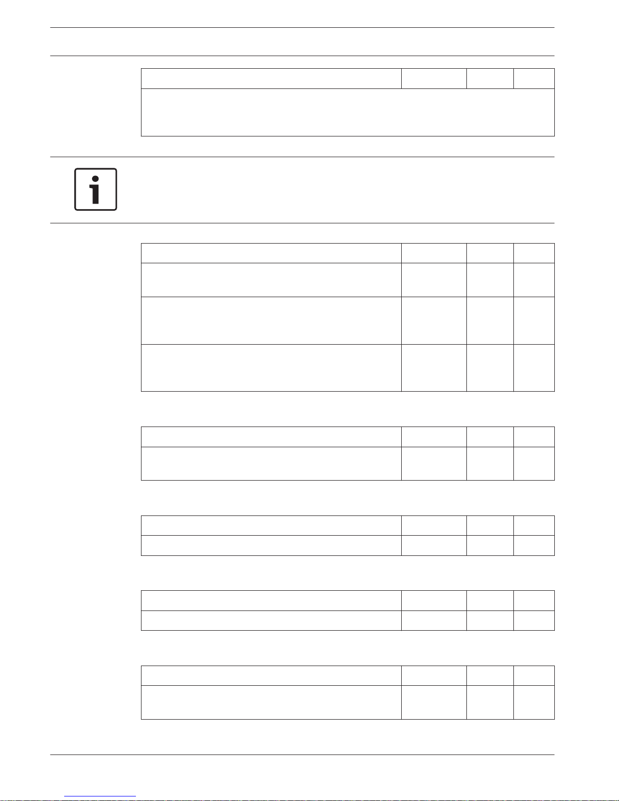
Automatic Test Report 0128 6
EN=1/5/6/7
0 = No report, 1 = Receiver 1, 2 = Receiver 2, 3 = Receiver 3, 4 = Receiver 4, 5 = Receiver
1,2,3 and 4, 6 = Receiver 1 (2,3 and 4 for backup), 7 = Receiver 1 (2 for backup) and receiver
3 (4 for backup)
Notice!
When the Transmission Format for Receiver in the receiver programming is set to 0 (not
used), i.e., setting the report option as sending report to a receiver, then the alarm control
panel will actually not send any report.
Automatic Test Report
Address 0129 - 0134 Address Default
Test Report Time: Interval
00 = Do not use timing report , 01 - 99 = 1 - 99 hours
0129 - 0130 24
VDS-A
EN=1=24
Report Time: Hour
00 - 23 = 0 - 23 hours, Others = Do not use real-time
report
0131 - 0132 99
Report Time: Minute
00 - 59 = 0 - 59 minutes, Others = Do not use real-time
report
0133 - 0134 99
Report Expiry Time
Address 0135 - 0137
Address Default
000 = No time limit, 001 - 255 = 1 - 255 minutes 0135 - 0137 000
VDS-A
EN=000
Installer Access Until Next Arming
Address
0138 Address Default
0 = disabled, 1 = enabled 0138 0
VDS-A=1
Force Arm When System Is In Trouble Condition
Address
0139 Address Default
0 = disabled, 1 = enabled 139 1
VDS-A EN=0
Siren / PO 1+2 Supervision
Address
0140 Address Default
0 = disabled, 1 = PO1 enabled, 2 = PO2 enabled, 3 =
PO1+2 enabled
0140 0
VDS-A EN=3
22 en | Configuration
AMAX panel 4000 / AMAX panel 4000
EN
2013.07 | 03 | F.01U.267.113 Quick Start Guide Bosch Sicherheitssysteme GmbH
 Loading...