

Bosch ICP-AMAX4-P1, ICP-AMAX4-P2-EN, ICP-AMAX-P3-EN, AMAX 4000, AMAX 4000EN Installation Manual
AMAX panel 4000 / AMAX panel 4000 EN
ICP-AMAX4-P1 / ICP-AMAX4-P2-EN / ICP-AMAX-P3-EN
en Installation Guide


Table of contents
1
Graphics 6
2
Safety 8
3
Short Information 9
4
System overview 10
5
Optional Modules and Peripheral Devices 11
5.1 Bosch Option Bus 11
5.2 Keypad 12
5.2.1 General 12
5.2.2 Address Setting 12
5.2.3 Wiring 13
5.2.4 Status Indicator 13
5.3 DX2010 13
5.3.1 General 13
5.3.2 Address Setting 14
5.3.3 Wiring 14
5.3.4 Status Indicator 15
5.4 DX3010 15
5.4.1 General 15
5.4.2 Address Setting 15
5.4.3 Wiring 16
5.4.4 Status Indicator 16
5.5 B426 17
5.5.1 General 17
5.5.2 Address Setting 17
5.5.3 Wiring 17
5.5.4 Status Indicator 17
5.6 DX4020-G 18
5.6.1 General 18
5.6.2 Address Setting 18
5.6.3 Wiring 18
5.6.4 Status Indicator 19
5.7 RF 3227E RF 19
5.7.1 General 19
5.7.2 Address Setting 19
5.7.3 Wiring 20
5.7.4 Status Indicator 21
5.8 RF Radion Receiver 21
5.8.1 General 21
5.8.2 Address Setting 21
5.8.3 Wiring 21
5.8.4 Status Indicator 21
6
Installation 23
6.1 Module Installation 23
6.2 Battery Installation 24
6.3 System Power Up 25
6.4 System Status Indicator 25
6.5 Prerequisites for Certification conform Installation 26
AMAX panel 4000 / AMAX panel 4000
EN
Table of Contents | en 3
Bosch Sicherheitssysteme GmbH Installation Guide 2014.4 | 01 | F.01U.267.112

6.5.1 EN 50131-3 Grade 2, Environmental Class 2 - AMAX 2100 / 3000 / 4000 26
6.5.2 NFA2P AFNOR / CNPP - AMAX 4000 28
6.5.3 INCERT - AMAX 4000 28
6.5.4 SFF – AMAX 2100 / 3000 / 4000 29
7
Settings 30
7.1 Communication and Reporting 30
7.1.1 Receivers 30
7.1.2 Reports 36
7.1.3 Automatic Test Report 40
7.1.4 Dual IP 40
7.1.5 Remote Access 40
7.1.6 Remote PC 41
7.1.7 Call back and Domestic Call 41
7.1.8 Ring Times 42
7.2 Codes 42
7.2.1 User Code and Code Commands 42
7.2.2 Installer Code 46
7.2.3 Code Length 46
7.2.4 Code Reporting 46
7.2.5 Code Permissions 47
7.3 Zones 47
7.3.1 Add / Delete Zone 47
7.3.2 Pulse Count Duration 55
7.3.3 Cross Zone Timer 55
7.3.4 Zone Function Settings 55
7.3.5 Zone Indication Keypad and Event Log 59
7.4 Keypads and Areas 60
7.4.1 Keypad Area 60
7.4.2 Area Timing 61
7.4.3 Common Area 61
7.4.4 Keypad Tone / Lockout 61
7.5 System 61
7.5.1 System Setting 61
7.5.2 System View 63
7.6 Outputs and Sirens 66
7.6.1 Outputs 66
7.6.2 Sirens 72
7.7 RF Devices 72
7.7.1 RF Options 72
7.7.2 RF Devices / User 73
7.8 Address and Key Programming 74
7.8.1 Address Programming 74
7.8.2 Programming with the ICP-EZPK Programming Key 74
8
Configuration 76
8.1 Programming with the Keypad 76
8.1.1 Text Keypad Menu Programming 76
8.1.2 LED/LCD Keypad Programming 84
8.2 PC Programming 85
8.2.1 Direct Connection 86
4 en | Table of Contents
AMAX panel 4000 / AMAX panel 4000
EN
2014.4 | 01 | F.01U.267.112 Installation Guide Bosch Sicherheitssysteme GmbH

8.2.2 Modem Connection 88
8.2.3 IP Connection 91
9
Address Programming 95
9.1 Communication and Reports Setting 95
9.2 Zone Programming 101
9.3 Output Programming 114
9.4 Access Codes 119
9.5 System Programming 121
10
Troubleshooting 138
10.1 General Trouble 138
10.2 Trouble Fault Inquiry 140
11
Maintenance 150
11.1 Firmware Upgrade with the ICP-EZRU2 Upgrade Key 150
12
Technical Data 151
AMAX panel 4000 / AMAX panel 4000
EN
Table of Contents | en 5
Bosch Sicherheitssysteme GmbH Installation Guide 2014.4 | 01 | F.01U.267.112
Graphics
Pro
gram Key Port
GND
-
+
A C
A
C
Transformer
Battery
Tam
per
L2 COM
COM
COM
L1a
L3
L4
L5
L6
L7
L8
L9
COM
COM
COM
COM
L10
L11
L12
L13
L14
L15
L16
P0+4
R
B
G
Y
AUX1
-
AUX2
-
AUX1
+12V
Y
G
B
R
RINGRHTHTIP
L1b
P0+3
P0+
P0-2
P0-1
Zones
Bosch Option
Bus 2 < 900mA
+12V
+
0 V
1
2
3
3
1 Tamper Switch
2 Zone Switch
3 EOL 2,2 k
3
2
3
2
Fuse 1 A
PO+4: < 750mA
PO+3: < 750mA
PO -2: < 500mA
PO -1: < 500mA
230V ~50Hz
230mA
Wac
hdog
outpu
t
<100
mA
12V < 18Ah
18VAC@50VA
Zones
AUX 1: < 900mA
AUX 2: < 900mA
AUX Power
Fir
e
Intrusion
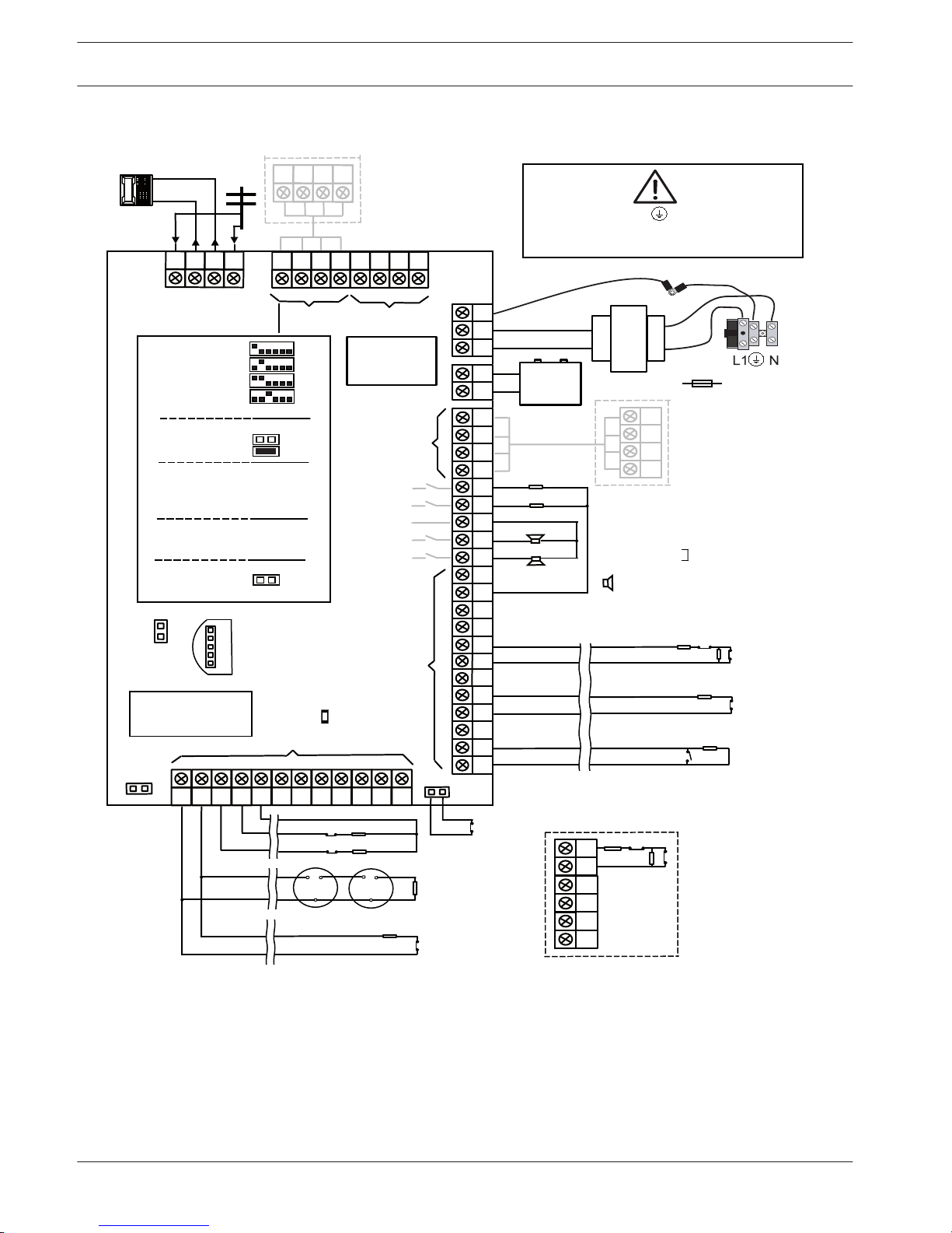
Risk of shock if N,L1 or is connected incorrectly.
For operation safety, the ground terminals must
be connected.
3
3
2
Slow flash: Normal state
On: Trouble state
Off: Trouble state
_
_
_
_
_
_
_
_
+12V
+12V
+12V
COM
_
12V 7Ah
AUX2
+12V
_
COM
supervised
PO-5
Z1
2
2
3
3
Keypads:
IUI-AMAX4-TEXT
IUI-AMAX3-LED16
IUI-AMAX3-LED8
Keypads:
IUI-AMAX-LED8
IUI-AMAX-LCD8
I/O Moduls:
DX2010 Adr. 103 - 108
DX3010 Adr. 150 - 151
DX4010 Adr. 253
Communicators:
DX4020G Adr. 134
B426 Adr. 134(6) / 250(9)
RF Receiver:
RF3227E 1=
RFRC-OPT 1= (1)
1 =
2
=
3 =
4
=
1 =
2 =
Bosch Option
Bus
1 < 900
mA
COM
R
B
G
Y
R
B
G
Y
R
B
G
Y
♥
IUI-AMAX3
+4 Keypad
3
1
2
1
Facto
ry
Default
5-16 Inst. Guide
I
2000mA
100 Ω - 2,2 k
_
<
∑
3
Figure 1.1: AMAX 4000
1
6 en | Graphics
AMAX panel 4000 / AMAX panel 4000
EN
2014.4 | 01 | F.01U.267.112 Installation Guide Bosch Sicherheitssysteme GmbH
Program Key P
ort
GND
-
+
AC
Transformer
Battery
Tam per
L8
12V
R
B
G
Y
1RING
TIP
P0+
P0-2
P0-1
1 Tamper Switch
2 Zone Switch
3 EOL 2,2 k
Fuse 500 mA
PO -2: < 500mA
PO -1: < 500mA
230V ~50Hz
85mA
18V-22V@20VA
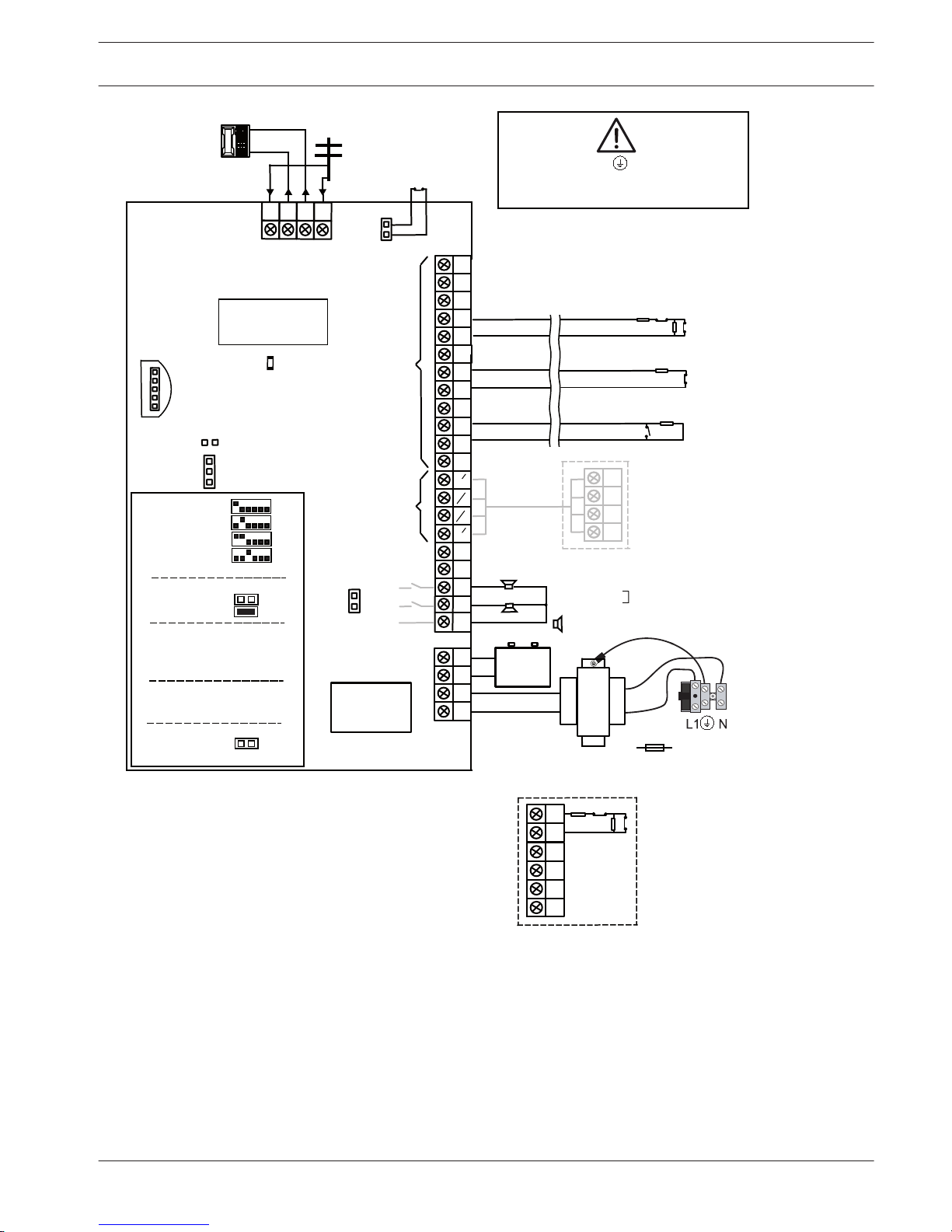
Risk of shock if N,L1 or is connected incorrectly.
For operation safety, the ground terminals must
be connected.
Slow flash: Normal state
On: Trouble state
Off: Trouble state
_
_
12V 7Ah
supervised
Z1
Keypads:
IUI-AMAX4-TEXT
IUI-AMAX3-LED16
IUI-AMAX3-LED8
Keypads:
IUI-AMAX-LED8
IUI-AMAX-LCD8
I/O Moduls:
DX2010 Adr. 102 - 105
DX3010 Adr. 150 - 151
DX4010 Adr. 253
Communicators:
DX4020G Adr. 134
B426 Adr. 134(6) / 250(9)
RF Receiver:
RF3227E 1=
RFRC-OPT 1= (1)
1 =
2
=
3 =
4
=
1
=
2
=
COM
R
B
G
Y
R
B
G
Y
♥
IUI-AMAX3 +4 Keypad
3
1
2
Factory
Default
5-8 Inst. Guide
I
1100mA
100 Ω - 2,2 k
_
<
∑
3
TIP
COM
L7
L6
COM
L5
COM
L4
L3
L2
COM
L1
AC
Zones
+12V
COM
COM
1
2
3
3
3
2
3
2
1
_
Bosch Option
Bus 1 < 500mA
OPT/SDI
COM
B
A
PWR
1RING
_
Rel
ay
PO-3: < 100mA
Figure 1.2: AMAX 2100/3000
AMAX panel 4000 / AMAX panel 4000
EN
Graphics | en 7
Bosch Sicherheitssysteme GmbH Installation Guide 2014.4 | 01 | F.01U.267.112
Safety
This system / product must be installed by a qualified installer / service person.
During installation and wiring, the AMAX power source must be switched off to prevent
equipment damage.
– To switch off the power source, an easy accessible circuit breaker must be available
– The system / product must be connected to a socket-outlet with a protective earthing
contact
The User has to disconnect all Telecommunication Network Connectors before unplugging the
power adaptor.
After the AMAX panel wiring is completed, connect the AC power and backup batteries.
The mains indicator on the keypad will light up show that AC power is connected.
Notice!
- Use only non spillable battery
- Battery must be recycled
- When battery is not replaced correctly, risk of fire explosion or burning
- Replace the battery every 3-5 years under normal conditions of use
- Place a label with change date on the battery
Notice!
- The system / product must be installed and maintained by qualified installer / service
person.
- Bosch recommends testing the alarm system at least once a week.
Danger!
As static-sensitive components are included in PCBs, anti-static steps should be followed and
they should be carefully installed.
Before installing the alarm AMAX panel, the static electricity should be discharged by
connecting the grounding terminal of the AMAX panel.
2
8 en | Safety
AMAX panel 4000 / AMAX panel 4000
EN
2014.4 | 01 | F.01U.267.112 Installation Guide Bosch Sicherheitssysteme GmbH

Short Information
Congratulations on selecting the AMAX panel for your installation. Spend some time reading
through this guide and familiarize yourself with the outstanding installation and operation
features of this system so that you can get the most from your unit. In all aspects of planning,
engineering, styling, operation, convenience, and adaptability, we try to anticipate your every
possible requirement. Programming simplicity and speed are our major considerations. We
believe that our objectives have been attained. This installation guide explains all aspects of
programming the AMAX panel from factory default to final commissioning. All system
parameters and options are dealt with in detail, but, adaptability differs with individuals. Each
AMAX panel can be tailored to meet your requirements quickly and easily. The programming
simplicity makes your installation quick, accurate, and rewarding.
3
AMAX panel 4000 / AMAX panel 4000
EN
Short Information | en 9
Bosch Sicherheitssysteme GmbH Installation Guide 2014.4 | 01 | F.01U.267.112
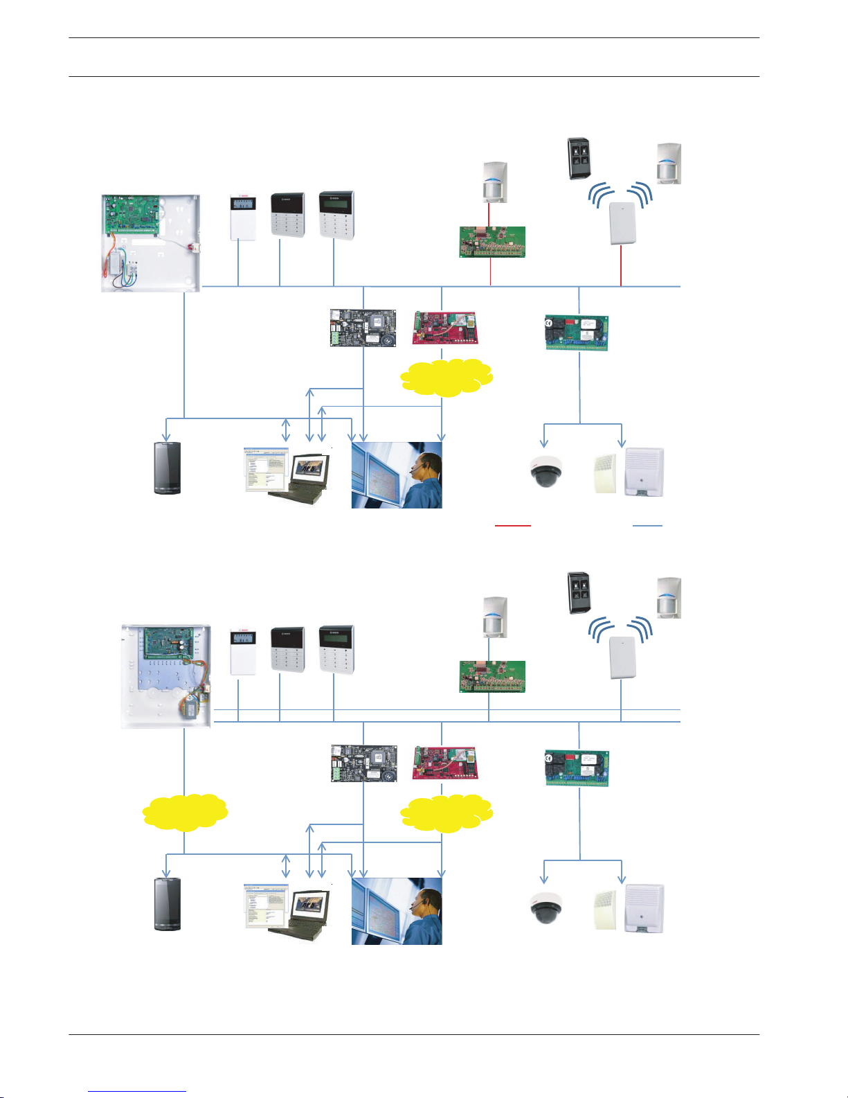
System overview
DX2010
Option Bus
B426
A Link Plus
CMS
IP
Video
DX4020G
PSTN
GSM/
GPRS
AMAX 3000 AMAX 2100 / 3000
Radion
DX3010
Text KeypadLCD / LED Keypad
AMAX 3000
AMAX 3000
Figure 4.1: AMAX 2100/3000 Overview
DX2010
Option Bus
B426
A Link Plus
CMS
IP
Video
DX4020G
PSTN
GSM/
GPRS
Radion
DX3010
Text KeypadLCD / LED Keypad
Figure 4.2: AMAX 4000 Overview
4
10 en | System overview
AMAX panel 4000 / AMAX panel 4000
EN
2014.4 | 01 | F.01U.267.112 Installation Guide Bosch Sicherheitssysteme GmbH
Optional Modules and Peripheral Devices
Bosch Option Bus
The AMAX panel provides the Bosch Option Bus to attach expansion modules. AMAX 2100 /
3000 each has one (Bosch Option Bus 1) and AMAX 4000 has two (Bosch Option Bus 1 and
2).
Maximum 14 modules (8 keypads) can be connected to each bus. The total length of the cable
for connection of all keypads and expansion modules wired to one Bosch Option Bus must not
exceed 700m. Particular modules require limitation in cable distance, f.e. the last keypad must
be placed within 200m.
The AMAX panel tests the communication with the modules and transmits the communication
failure report in case of failure of communication.
Cable Details:
– R: AUX 12V +
– B: 12V –
– G: Data
– Y: Data
Notice!
The AMAX panel 2100 / 3000 provides 12 VDC power supply with maximum 500mA for Bosch
option bus 1. The AMAX panel 4000 provides a maximum 900mA for each Bosch option bus 1
and 2. When the total current of the bus exceeds the limit, an external power supply is
required.
Notice!
When data bus address is changed, the module needs to be re-powered to make the new
address effective.
Bosch Option Bus Module –
AMAX Panel
2100 3000 4000
Keypads 4 8 16
DX3010 1 2
B426 or DX4020 2 / 1 if DX4020G is used
DX4020G 1
DX2010 3 6
DX4010 1
RF receiver 1
Table 5.1: AMAX panel number of Bosch Option Bus modules
5
5.1
AMAX panel 4000 / AMAX panel 4000
EN
Optional Modules and Peripheral Devices | en 11
Bosch Sicherheitssysteme GmbH Installation Guide 2014.4 | 01 | F.01U.267.112
Keypad
General
AMAX panel supports five types of keypad as follows:
– IUI-AMAX4-TEXT (LCD Text Keypad)
– IUI-AMAX3-LED16 (16 Zone LED Keypad)
– IUI-AMAX3-LED8 (8 Zone LED Keypad)
– IUI-AMAX-LED8 (8 Zone LED Keypad)
– IUI-AMAX-LCD8 (8 Zone LCD Keypad)
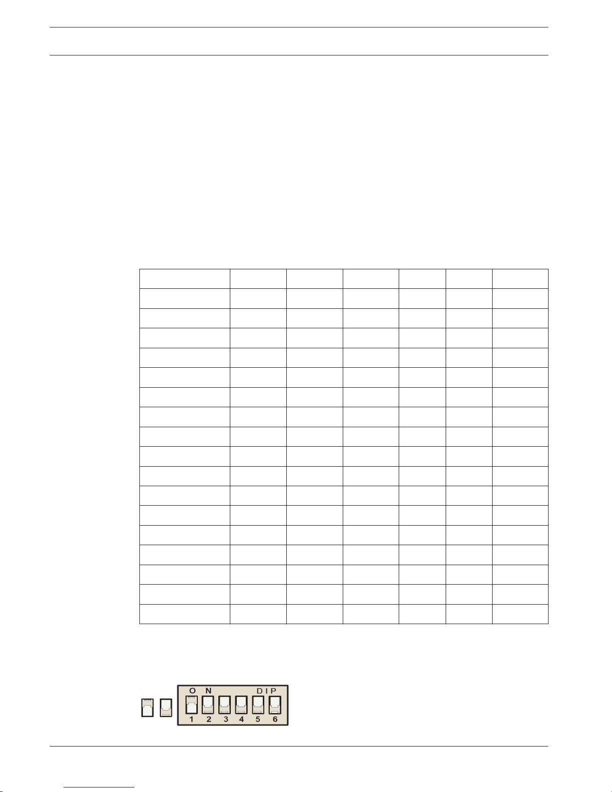
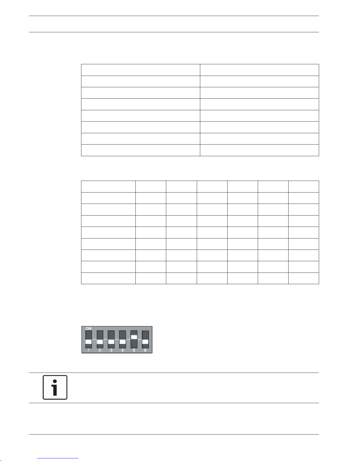
Address Setting
For IUI-AMAX4-TEXT, IUI-AMAX3-LED16, IUI-AMAX3-LED8 keypads, the address of the keypad is
programmed with 6-position DIP switch. The address of each keypad is unique.
DIP Switch S1 S2 S3 S4 S5 S6
Keypad Address 1 2 3 4 5 6
1 On Off Off Off Off Off
2 Off On Off Off Off Off
3 On On Off Off Off Off
4 Off Off On Off Off Off
5** On Off On Off Off Off
6** Off On On Off Off Off
7** On On On Off Off Off
8** Off Off Off On Off Off
9* On Off Off On Off Off
10* Off On Off On Off Off
11* On On Off On Off Off
12* Off Off On On Off Off
13* On Off On On Off Off
14* Off On On On Off Off
15* On On On On Off Off
16* Off Off Off Off On Off
Table 5.2: Keypad Address Settings
* AMAX4000
** AMAX3000/4000
On Off
Figure 5.1: 6-Position DIP Switch
5.2
5.2.1
5.2.2
12 en | Optional Modules and Peripheral Devices
AMAX panel 4000 / AMAX panel 4000
EN
2014.4 | 01 | F.01U.267.112 Installation Guide Bosch Sicherheitssysteme GmbH
DIP switches 5 and 6 are not used.
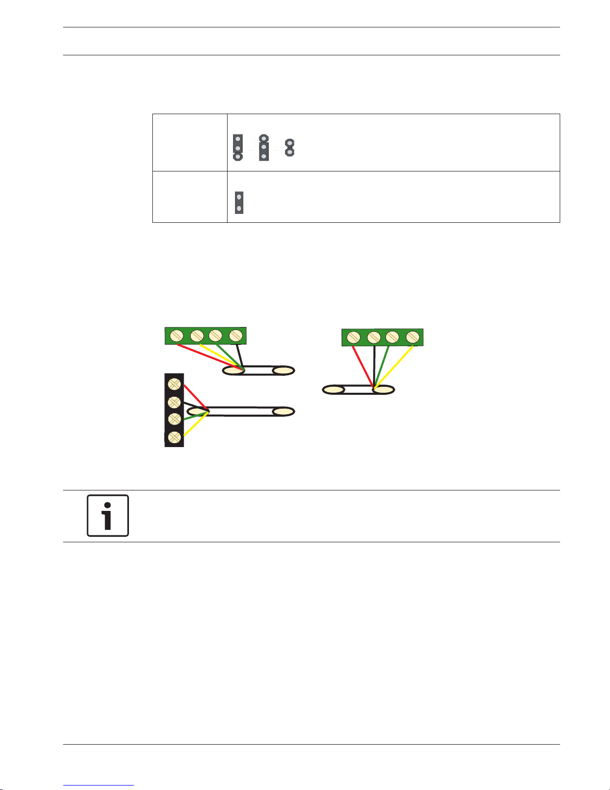
IUI-AMAX-LED8 and IUI-AMAX-LCD8 keypads can be set only to address 1 or address 2 through
the address jumper.
Address 1 Jumper not short-circuited
Address 2 Jumper short-circuited (both metal pins are covered)
Table 5.3: Keypad Jumper Settings
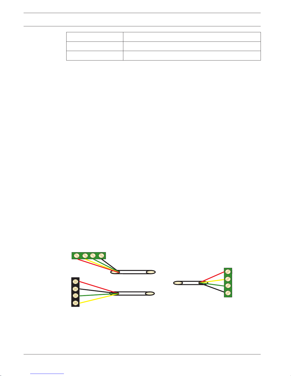
Wiring
Connect the keypad to Bosch Option Bus of AMAX panel according to the following figure. The
last keypad must be placed within a cable distance of 200m.
AMAX 4000
Y
R
Y
G
B
AMAX 2100 / 3000
Keypad
R
B
G
R
B
G
Y
Figure 5.2: Connecting keypad to the AMAX Panel
Notice!
One single Bosch Option Bus is limited up to 8 keypads.
Status Indicator
If all indicators are blinking, then the keypad loses data connection to the AMAX panel.
DX2010
General
The AMAX panel supports DX2010 input expansion modules. Each expansion module supports
up to 8 zone inputs.
See also
– Module Installation, page 23
5.2.3
5.2.4
5.3
5.3.1
AMAX panel 4000 / AMAX panel 4000
EN
Optional Modules and Peripheral Devices | en 13
Bosch Sicherheitssysteme GmbH Installation Guide 2014.4 | 01 | F.01U.267.112
Address Setting
Each DX2010 module connected to the AMAX panel must have its own data bus address.
Data Bus Address Zones
102*** 9 - 16
103** 17 - 24
104** 25 - 32
105* 33 - 40
106* 41 - 48
107* 49 - 56
108* 57 - 64
Table 5.4: DX2010 Address Settings
DIP Switch
S1 S2 S3 S4 S5 S6
Data Bus Address 32 16 8 4 2 1
102*** Off Off Off Off Off On
103** Off Off Off Off On Off
104** Off Off Off Off On On
105* Off Off Off On Off Off
106* Off Off Off On Off On
107* Off Off Off On On Off
108* Off Off Off On On On
Table 5.5: DX2010 DIP Switch Settings
* AMAX 4000
** AMAX 3000 / 4000
*** AMAX 3000
Example : Data Bus Location 103 - DIP Settings
Figure 5.3: DX2010 DIP Switch Settings
Notice!
When data bus address is changed, the module needs to be re-powered to make the new
address effective.
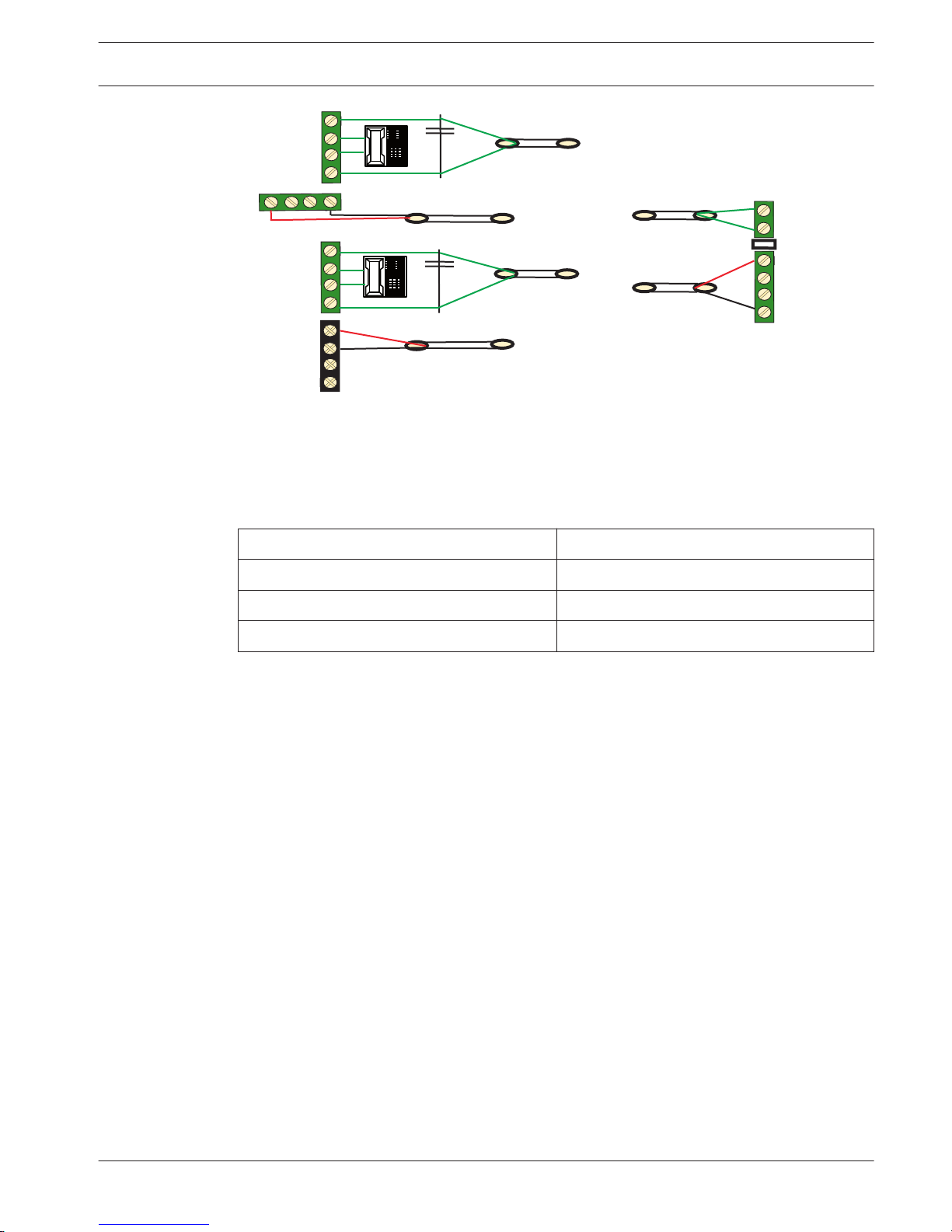
Wiring
Do not use twisted pair or shielded cables to connect DX2010 and the AMAX panel.
5.3.2
5.3.3
14 en | Optional Modules and Peripheral Devices
AMAX panel 4000 / AMAX panel 4000
EN
2014.4 | 01 | F.01U.267.112 Installation Guide Bosch Sicherheitssysteme GmbH
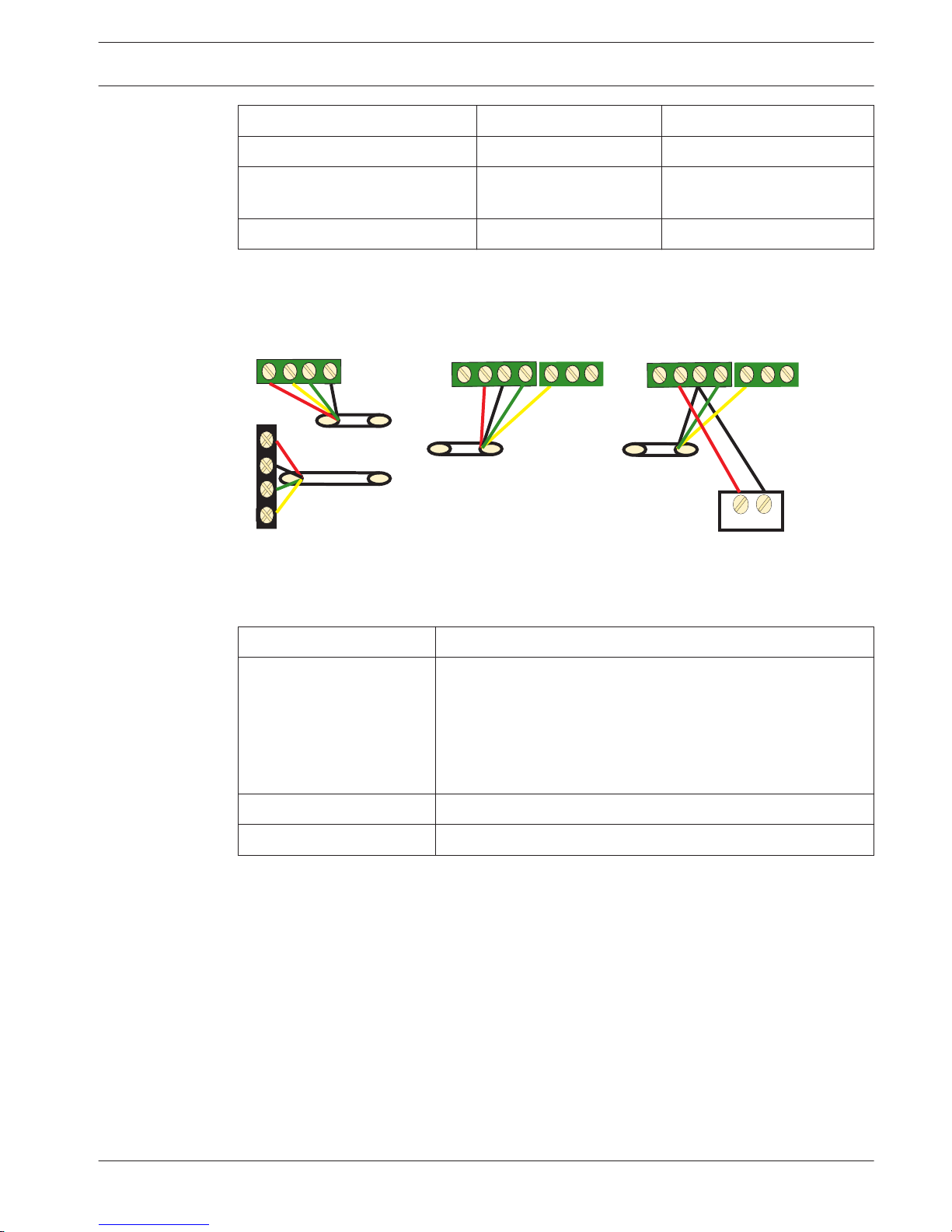
Power Supply Wire diameter of 0.8mm Wire diameter of 1.2mm
AMAX Panel 30m 76m
AMAX Panel (DX2010 Out not
used)
305m 610m
External Power Supply 305m 610m
Table 5.6: Lengths of cable for DX2010
+
12V
AMAX 4000
Y
R
Y
G
B
R
B
G
_
R
B
G
Y
1
COM
TMPR
R
B
G
Y
1
COM
TMPR
AMAX 2100 / 3000
DX2010
DX2010
Figure 5.4: Connecting DX2010 to the AMAX Panel
Status Indicator
LED Condition Denotation
On Trouble Condtion:
– Grounding Conductor is not connected or there is a
communication failure between the module and the AMAX
panel.
– No zones distributed
– Module address setting error
Flash (once per second) Normal Operation
Off Power failure
DX3010
General
The AMAX panel supports DX3010 output expansion modules. Each module supports eight
fully programmable relay outputs. For more information about installation, see DX3010
Installation Guide.
See also
– Module Installation, page 23
Address Setting
Each DX3010 module connected to the AMAX panel must have its own data bus address.
5.3.4
5.4
5.4.1
5.4.2
AMAX panel 4000 / AMAX panel 4000
EN
Optional Modules and Peripheral Devices | en 15
Bosch Sicherheitssysteme GmbH Installation Guide 2014.4 | 01 | F.01U.267.112
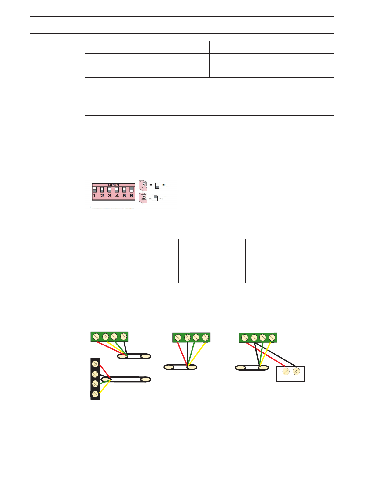
Data Bus Address Outputs
150 5-12
151* 13-20
Table 5.7: DX3010 Address Settings
DIP Switch S1 S2 S3 S4 S5 S6
Data Bus Address 1 2 4 8 16 Mode
150 On On On On On Off
151* Off On On On On Off
Table 5.8: DX3010 DIP Switch Settings
* AMAX 3000 / 4000
Example : Data Bus Location 150 - DIP Settings
On
Off
Figure 5.5: DX3010 DIP Switch Settings
Wiring
Power Supply Wire diameter of
0.8mm
Wire diameter of 1.2mm
AMAX Panel 12.2m 24.4m
External Power Supply 305m 610m
Table 5.9: Lengths of cable for DX3010
+
12V
AMAX 4000
Y
R
Y
G
B
AMAX 2100 / 3000
DX3010
R
B
G
DX3010
R
B
G
Y
R
B
G
Y
_
Figure 5.6: Connecting DX3010 to the AMAX Panel
Status Indicator
None.
5.4.3
5.4.4
16 en | Optional Modules and Peripheral Devices
AMAX panel 4000 / AMAX panel 4000
EN
2014.4 | 01 | F.01U.267.112 Installation Guide Bosch Sicherheitssysteme GmbH
B426
General
AMAX panel supports up to two communication modules.
– ITS-DX4020-G and B426 or B426 and B426
The B426 Ethernet communication module supports monitored two-way IP communication via
Ethernet to perform alarm transmission, remote programming, and control of the AMAX panel.
Before installing B426, all power supplies (AC power supply and backup battery power
supply) of the AMAX panel should be disconnected. Use the standard three-hole installation
mode to install B426 in the enclosure of the AMAX panel or in another enclosure. To
reconfigure the module or connected to the alarm control panel with RPS, the network or
direct connection must be used to access its built-in Web server.
For more information about installation and configuration, see B426 Installation and Operating
Guide.
Address Setting
Turn the rotary switch to 6, i.e., set the address to 134 when the first B426 is used. Turn the
rotary switch to 9, i.e., set the address to 250 when the second B426 is used.
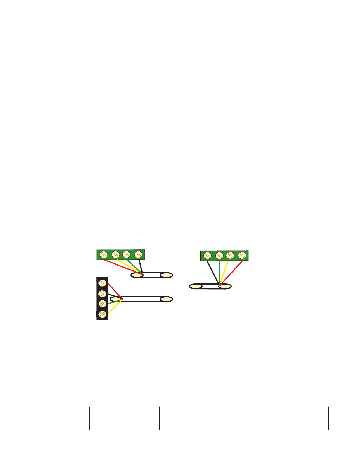
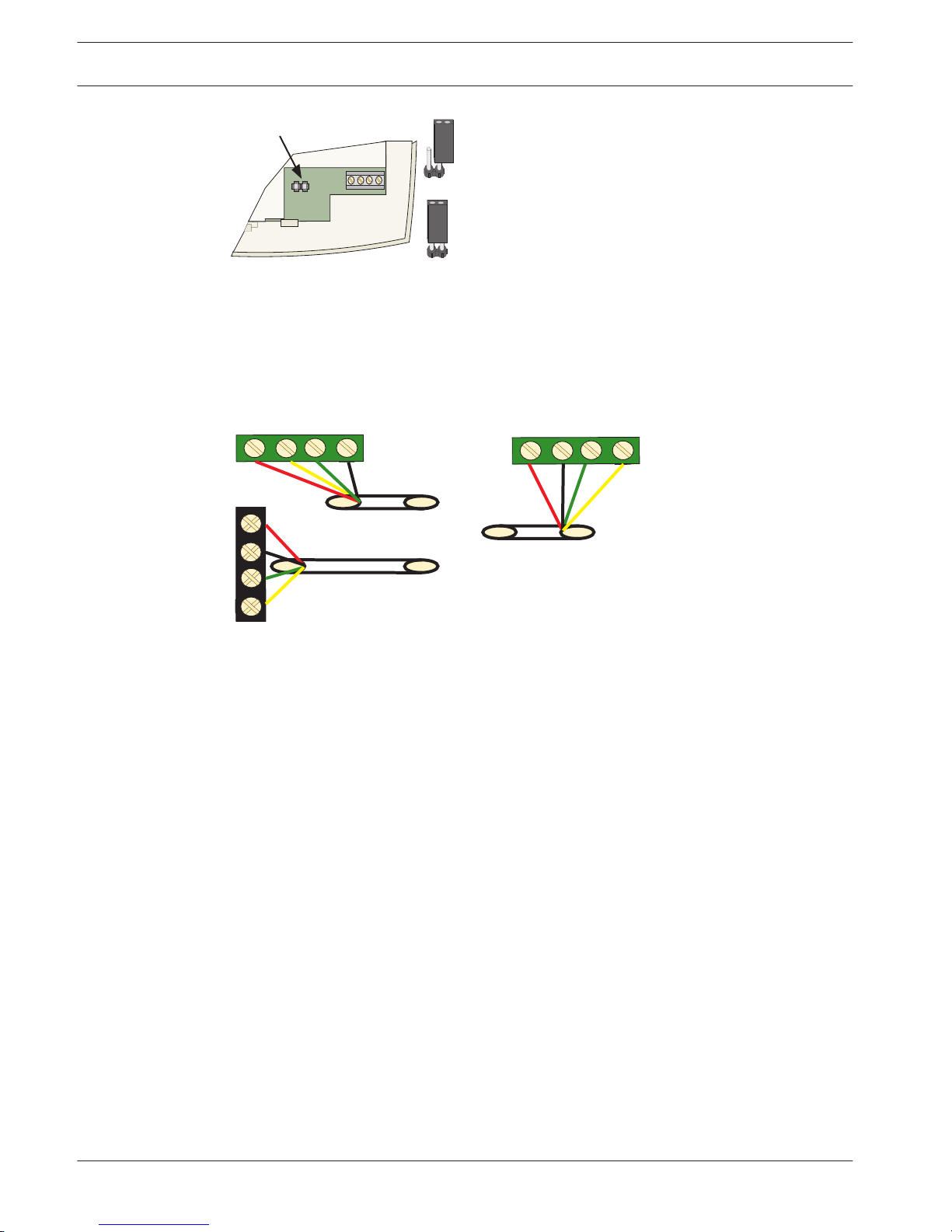
Wiring
Connect B426 to Bosch option Bus 1 or 2. The cable may not exceed 150 meters.
AMAX 4000
Y
R
Y
G
B
AMAX 2100 / 3000
B426
R
B
G
R
B
G
Y
Figure 5.7: Connecting B426 to the AMAX Panel
Status Indicator
B426 provides the following on-board LED indicators to help in troubleshooting.
– Blue system status indicator.
– Green data bus indicator.
– Green Ethernet link indicator.
LED Condition Denotation
On Trouble Condition
5.5
5.5.1
5.5.2
5.5.3
5.5.4
AMAX panel 4000 / AMAX panel 4000
EN
Optional Modules and Peripheral Devices | en 17
Bosch Sicherheitssysteme GmbH Installation Guide 2014.4 | 01 | F.01U.267.112
Flash (stable flash) Normal Operation
Flash (3 flashes) Normal power supply, without communication
Off Power failure or other failure conditions
Table 5.10: B426 System Status Indicator
For more information about indicators, see B426, page 17.
DX4020-G
General
The Conettix ITS-DX4020-G GPRS communication module allows IP communication via
commercial GPRS network. Transmission of alarm information via GPRS is the default for ITSDX4020-G. SMS or USB mode can be chosen for configuration. Remote programming and
control of the AMAX panel is supported.
Installation
1. Before installing ITS-DX4020-G, all power supplies of the AMAX panel should be
disconnected.
2. Insert SIM card.
3. Use the standard three-hole installation mode to install the ITS-DX4020-G in the enclosure
of the AMAX panel or another enclosure.
4. Connect the magnetic antenna to ITS-DX4020-G.
Address Setting
Set bus address to 134.
See also
– DX4020-G, page 18
Wiring
The connection of ITS-DX4020-G and the AMAX panel is divided into two modes: GPRS and
GSM.
AMAX 4000
Y
R
Y
G
B
AMAX 2100 / 3000
R
B
G
DX4020G
R
B
G
Y
Figure 5.8: GPRS Mode in Support of IP
5.6
5.6.1
5.6.2
5.6.3
18 en | Optional Modules and Peripheral Devices
AMAX panel 4000 / AMAX panel 4000
EN
2014.4 | 01 | F.01U.267.112 Installation Guide Bosch Sicherheitssysteme GmbH
DX4020G
BUS
AMAX 4000
R
Y
G
B
RING
TIP
RH
TH
R
B
G
Y
PNL
PSTN
TIP
TIP
1RING
1RING
R
Y
G
B
AMAX 2100 / 3000
Figure 5.9: GSM Mode in Support of PSTN (Contact ID)
Status Indicator
The AMAX panel tests the communication normally with the module. In case of communication
failure, a fault report including the module address is sent.
LED Condition Denotation
On Normal Condition
Flash Trouble Condition
Off Power Failure
Table 5.11: DX4020-G System Status Indicator
For more information on indicators, configuration and other topics related to ITS-DX4020-G,
see Installation and Operation Guide.
RF 3227E RF
General
The RF3227E RF receiver allows the use of wireless devices using the AMAX panel 3000 /
4000.
Installation
Whenever possible, the receiver should be mounted in a central location with regard to all
wireless sensors. The receiver should be mounted vertically, with at least 25 cm clearance
above it for the antennas. Avoid mounting the receiver in areas with significant metal or
electrical wiring such as furnace, or utility rooms. If this is unavoidable, mount the receiver
with the antennas extending above any metal surface. Avoid mounting the receiver in areas
where it may be exposed to moisture. Reception distances are generally improved with higher
mounting locations and with no metal objects near the antennas.
Address Setting
Set receiver address to #1. The AMAX panel supports only receiver 1, not receiver 2.
5.6.4
5.7
5.7.1
5.7.2
AMAX panel 4000 / AMAX panel 4000
EN
Optional Modules and Peripheral Devices | en 19
Bosch Sicherheitssysteme GmbH Installation Guide 2014.4 | 01 | F.01U.267.112
No Jumper = Receiver # 1 (Default)
Jumper = Receiver # 2
Address Jumper
Jumper left on pin for storage only.
R
B
G
Y
ADDR
Figure 5.10: Address
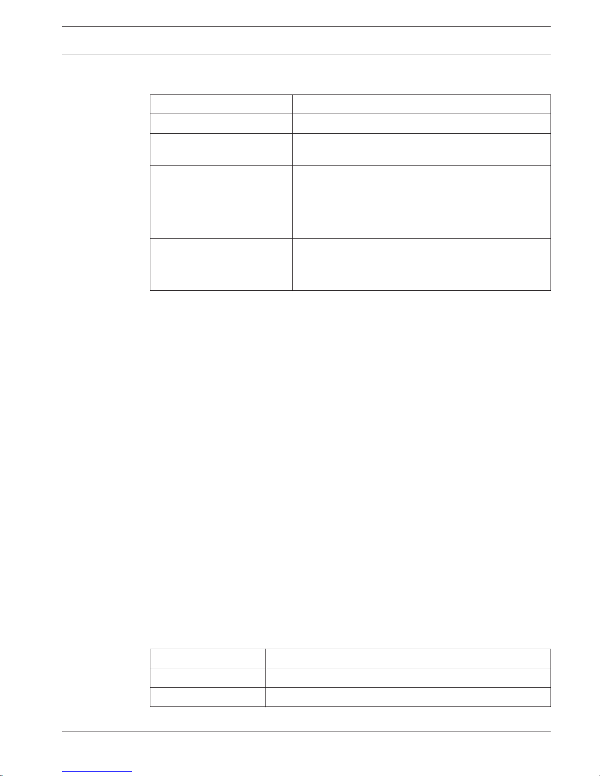
Wiring
Connect the RF3227E receiver to Bosch option Bus. The cable must not exceed 300 m. Adding
additional devices to the bus might reduce the maximum distance. Shielded cable is not
required. Do not use twisted pair wires.
AMAX 4000
Y
R
Y
G
B
AMAX 2100 / 3000
RF3227E
R
B
G
R
B
G
Y
Figure 5.11: Connecting RF3227E
5.7.3
20 en | Optional Modules and Peripheral Devices
AMAX panel 4000 / AMAX panel 4000
EN
2014.4 | 01 | F.01U.267.112 Installation Guide Bosch Sicherheitssysteme GmbH
Status Indicator
LED Condition Denotation
On Normal Operation
Momentarily on The receiver has acknowledged receiving a message from a
compatible transmitter.
Flashes rapidly for less than one
minute
The receiver is being programmed with zone and
transmitter IDs from the AMAX panel. This condition occurs
during system initialization (power up), or when new zone
information is programmed into the system. The rapid
flashing lasts for less than one minute.
Flashes rapidly for more than
one minute
The receiver has failed power-up self tests. Replace the
receiver.
Off Power failure or wiring failure
Table 5.12: RF 3227E RF System Status Indicator
RF Radion Receiver
General
RADION receiver OP is a wireless receiver that connects the RADION Wireless System
components to the AMAX panel 3000 / 4000. Features include:
– Cover and wall tamper protection
– RFID and configuration data are contained in persistent memory
– Detection and reporting of radio frequency interference
– Supports two types of device enrollment
Installation
Use the provided anchors and screws to mount the receiver in locations accessible for future
maintenance. Mount the receiver onto a wall.
For best reception, place the receiver in a central location among the transmitters. In
situations where there is a large distance between the transmitter and receiver, it might be
necessary to install receivers for optimum results.
Address Setting
Set rotary switch to value 1. The AMAX panel supports one receiver only.
Wiring
Connect the RADION receiver to bosch option bus. The cable distance to the AMAX panel may
not exceed 300 meters.
Status Indicator
LED Condition Denotation
On Normal operation
Off Power failure or wiring failure
5.7.4
5.8
5.8.1
5.8.2
5.8.3
5.8.4
AMAX panel 4000 / AMAX panel 4000
EN
Optional Modules and Peripheral Devices | en 21
Bosch Sicherheitssysteme GmbH Installation Guide 2014.4 | 01 | F.01U.267.112
Continuous Flash: 1 sec
On, 1 sec Off
Receiver is being programmed with the zone and transmitter IDs
from the AMAX panel.
Turns Off momentarily Receiver has obtained a valid transmission from a RADION
transmitter.
Continuous Flash: A 3pulse signal, followed by
a short delay at the end
of the 3rd pulse
Communication error and / or a self-test failure.
Causes:
– A communication failure between the AMAX panel and the
receiver or
– An invalid address switch setting.
Table 5.13: RFRC-OPT Radion Receiver System Status Indicator
22 en | Optional Modules and Peripheral Devices
AMAX panel 4000 / AMAX panel 4000
EN
2014.4 | 01 | F.01U.267.112 Installation Guide Bosch Sicherheitssysteme GmbH
Installation
This chapter specifies installation and system power up of the AMAX panel.
During installation and wiring, the AMAX panel power source must be switched-off to prevent
equipment damage.
– To switch off the power source, an easy accessible circuit breaker must be available
– The system / product must be connected to a socket-outlet with a protective earthing
contact
The User has to disconnect all Telecommunication Network Connectors before unplugging the
power adaptor.
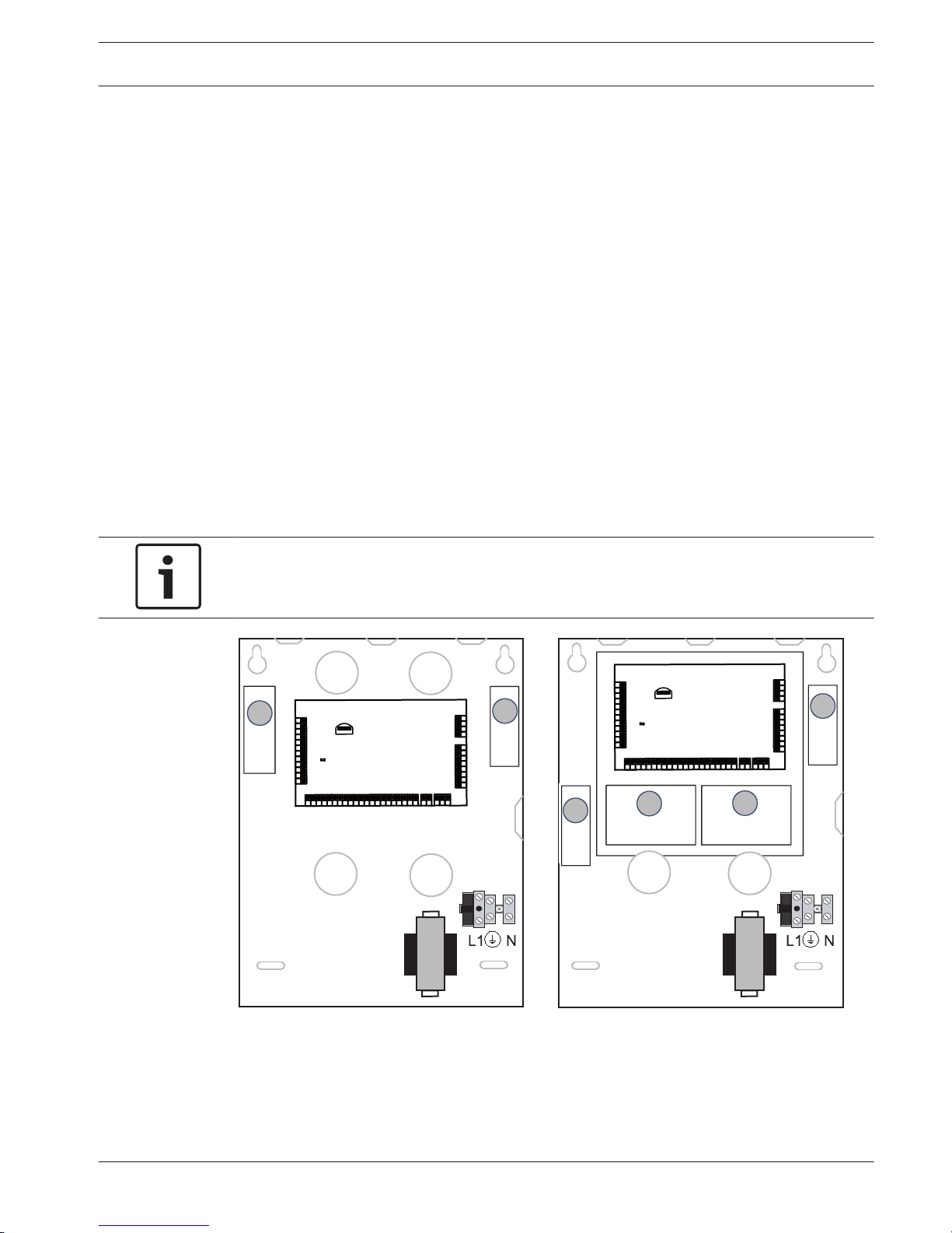
Module Installation
The enclosure contains only PCBs and transformers of the fixed AMAX panel, not other
hardware for installation.
1. Open the knockout holes for wiring in the module.
2. Position two upper mounting holes on the installation wall with the module.
3. Pre-install screws on the mounting holes (provided by the installer).
4. Mount the screws on the module.
5. Fasten the screws.
6. Fix the two lower mounting holes with screws.
Notice!
Please choose appropriate positioning screw kit when you have to install in a non-load
bearing wall.
E N √ E N √
2
Enclosure - Standard
Enclosure with mounting plate
GND
-
+
AC
AC
L2
COM
COM
COM
L1a
L3
L4
L5
L6
L7
L8
L9
COM
COM
COM
COM
L10
L11
L12
L13
L14
L15
L16
P0+4
R
B
G
Y
AUX1
-
AUX2
-
AUX1
+12V
Y
G
B
R
RINGRHTHTIP
L1b
P0+3
P0+
P0-2
P0-1
AUX2
+12V
♥
GND
-
+
AC
AC
L2 COM
COM
COM
L1a
L3
L4
L5
L6
L7
L8
L9
COM
COM
COM
COM
L10
L11
L12
L13
L14
L15
L16
P0+4
R
B
G
Y
AUX
1
-
AUX
2
-
AUX
1
+12V
Y
G
B
R
RINGRH
TH
TIP
L1b
P0+3
P0+
P0-2
P0-1
AUX
2
+12V
♥
1
2
1
3
4
Figure 6.1: Enclosure / with mounting plate
6
6.1
AMAX panel 4000 / AMAX panel 4000
EN
Installation | en 23
Bosch Sicherheitssysteme GmbH Installation Guide 2014.4 | 01 | F.01U.267.112
GND
-
+
AC
L8
12V
R
B
G
Y
1RING
TIP
P0+
P0-2
P0-1
TIP
COM
L7
L6
COM
L5
COM
L4
L3
L2
COM
L1
AC
COM
B
A
PWR
1RING
♥
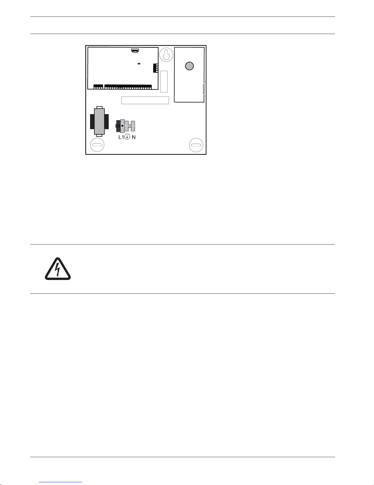
EN √
1
Figure 6.2: Enclosure / with mounting plate
Expansion modules can be placed in enclosure of the AMAX panel. Several places are
available. Figure 6.1. shows standard enclosure installation and enclosure installation with
mounting plate.
Battery Installation
The AMAX Panel supports one sealed lead-acid rechargeable battery. After the battery is fully
charged, it can be used as backup power supply to support the system.
Please refer to , page 151
Danger!
Special care is required in connecting the positive (red) wire and the “BATT +” port of the
AMAX panel. If you short-circuit the “BATT +” port of the AMAX panel or the enclosure, an
electric arc will occur. To remove the battery from the AMAX panel, the positive wire of the
battery should be disconnected first.
1. Place the battery on the bottom of the enclosure.
2. Position the red and black wires.
3. Connect one end of the black wire to the "BATT -" port of the AMAX panel, and the other
end to the negative (-) pole of the battery.
4. Connect one end of the red wire to the "BATT +" port of the AMAX panel, the other end to
the positive (+) pole of the battery.
Once the installation is complete, the AMAX panel will begin to charge the battery.
6.2
24 en | Installation
AMAX panel 4000 / AMAX panel 4000
EN
2014.4 | 01 | F.01U.267.112 Installation Guide Bosch Sicherheitssysteme GmbH
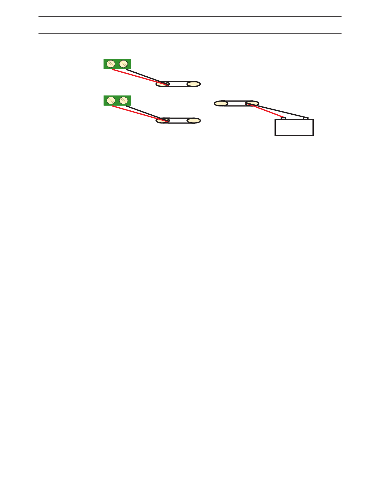
AMAX 2100 / 3000
AMAX 4000
+
_
BATTERY
+
_
BATT
+
Battery
_
Figure 6.3: Connection of Battery
System Power Up
After the AMAX panel is powered up, set the date and time. Otherwise, the system prompts as
fault.
After the AMAX panel is powered up or reset, it resets to previous arming / disarming status.
To reduce false alarms caused by system power-up (or by power supply restoration after both
mains supply and AUX power supply fail), the AMAX panel is designed to not perform zone test
within one minute after power-up.
System Status Indicator
The AMAX panel indicates the system status by using the LED status indicator on the system
main board.
Slow flash of red on status indicator (repeating on and off with an interval of 1 second)
indicates normal system operation.
6.3
6.4
AMAX panel 4000 / AMAX panel 4000
EN
Installation | en 25
Bosch Sicherheitssysteme GmbH Installation Guide 2014.4 | 01 | F.01U.267.112
Prerequisites for Certification conform Installation
EN 50131-3 Grade 2, Environmental Class 2 - AMAX 2100 / 3000 / 4000
The P anel complies with the Following Standards:
EN 50131- 3
EN 50131- 6
EN 50136 - 2- 1
EN 50136 - 2- 3
Certification Body
VDS Schadenverhütung
Amsterdamer Str.172
50735 Köln
www.vds.de
– The system / product must be placed inside the monitored area on a stable surface
– Keypads must be mounted to the inner side of the monitored area
– Once the system is tested and ready to use, enclosure door and accessory enclosures
must be secured with the provided screws
– To realize EN conform Alarm Indication and Transmission, one of the following devices
must be used
– Two supervised Warning devices (PO-1 PO-2 & PO+) and one ATS 2 Communicator
(onboard Dialer, B426, D4020 or DX4020G)
– One self powered Warning Device and one ATS 2 Communicator (onboard Dialer,
B426, D4020 or DX4020G)
– Two Communicators, one ATS 2 (onboard Dialer, B426, D4020 or DX4020G) and one
ATS 1 (onboard Dialer, B426, D4020 or DX4020G)
– One ATS 3 Communicator (DX4020 or B426)
All Communicators must be connected to a central monitoring station.
Only the onboard Dialer and the Option Bus Communicators can be used for EN Alarm
Transmission.
– one 12V / 7AH or one 12V / 18Ah Battery must be connected to the System
– maximum current for all components with a 7Ah Battery = 550mA
– maximum current for all components with a 18Ah Battery = 1500mA (standby 12h,
recharge battery 80% in 72h) (PCB =l 00mA, IUI-AMAX Keypads = 31mA, DX2010 = 35mA,
DX3010 = 10mA, B426 = 100mA, DX4020G = 65mA, RF3227E = 30mA, RFRC-OPT = 30mA)
– To realize EN conform Arming procedure, an indication of arm / disarm status must be
accessible from outside the monitored area (this indication can be time limited)
– To realize EN conform Access to the Monitored Area, one of the following methods must
be used
– Opening a door (to the entry / exit route) must start the entry procedure
– Indication of arm / disarm Status
6.5
6.5.1
26 en | Installation
AMAX panel 4000 / AMAX panel 4000
EN
2014.4 | 01 | F.01U.267.112 Installation Guide Bosch Sicherheitssysteme GmbH

– Access to the monitored area (doors not starting entry procedure) is prevented (e.g.
door strike, mechanically)
– The Enclosure lock can only be used in non EN setup
– Telephone arming can only be used in non EN setup
– Accessory Modules, except input module (DX2010) can be used only inside the enclosure
(on the adapter plate)
– When input module (DX2010) is used in the external enclosure (AE20), the tamper skirt
must be installed on the PCB of input module (DX2010)
– The panel must be programmed with the EN settings indicated on the programming sheet
– When the panel is set without EN parameters, the EN Indication (on Label) must be
removed
– Maximum of 10 Devices shall be connected to one Zone Input (Panel, Keypad, Input
Module, RFUN,…)
AMAX panel 4000 / AMAX panel 4000
EN
Installation | en 27
Bosch Sicherheitssysteme GmbH Installation Guide 2014.4 | 01 | F.01U.267.112
NFA2P AFNOR / CNPP - AMAX 4000
Certification Body
:
AFNOR Certification
11, rue Francis de Pressensé
93571 LA PLAINE Saint Denis Cedex
Tel: + 33 (0)1 41 62 80 00
Fax: + 33 (0)1 49 17 90 00
Web sites:
www.afnor.org
and www.marque-nf.com
Email: certification@afnor.org
The Panel complies with the Following Standards:
RTC 50131-3 NF3248H58-2011 V1
RTC 50131-6 NF3248H58-2011 V1
Reference:
NF324 H58 2.5 Option 3: Grade 2 (European EN sta ndards) + RTC
Certification Body:
CNPP Cert.
Route de la Chapelle Réanville
CS 22265
27950 SAINT MARCEL
Tel: (33) 2 32 53 63 63
Fax: (33) 2 32 53 64 46
Website:
www.cnpp.com
Email:
certification@cnpp.com
Prerequisites for an NFa2p conform Installation
- When aNFa2p conform instalation is made, the environmental class of the Panel is "1”
Certification Number: 1223400001A0
INCERT - AMAX 4000
6.5.2
6.5.3
28 en | Installation
AMAX panel 4000 / AMAX panel 4000
EN
2014.4 | 01 | F.01U.267.112 Installation Guide Bosch Sicherheitssysteme GmbH
SFF – AMAX 2100 / 3000 / 4000
Certification Body
SSF Stöldskyddsföreningen
Amsterdamer Str.172
50735 Köln
www.vds.de
VDS Schadenverhütung
Tegeluddsvägen 100
115 87 Stockholm
http://www.stoldskyddsfpreningen.se
The P anel complies with the Following Standards:
SSF 1014 Edition 4 Alarm class 1
6.5.4
AMAX panel 4000 / AMAX panel 4000
EN
Installation | en 29
Bosch Sicherheitssysteme GmbH Installation Guide 2014.4 | 01 | F.01U.267.112
Settings
This chapter specifies the properties and the behavior of the AMAX panel.
Communication and Reporting
This section outlines the programming information required for the AMAX panel when
communicating with a base station receiver. These parameters specify the telephone
numbers/IP address to be called, transmission formats, and internet communication options.
Receivers
Receiver Telephone number / IP Address and Port
The AMAX panel can report event information from four on-board dialers. The dialers report to
Receiver 1 to Receiver 4 by programming. You can program each dialer with 4 separate
telephone numbers/IP addresses and ports, reporting format type and subscriber ID number,
and internet communication options if necessary.
Example
You can set up Dialer 1 to report to receiver 1 in Bosch Network (Conettix) Format and set up
Dialer 2, Dialer 3, and Dialer 4 to report to a receiver of a central monitoring station in Contact
ID Format only, if Dialer 1 is unsuccessful.
To program a telephone number:
Each address in the telephone numbers stores one digit of the telephone number.
Insert a 15 at the end of a telephone number to indicate to the dialer that the end of the
telephone number is reached. The dialing sequence is terminated when a 15 appears.
Example
To program the telephone number 9672 1055 as the Telephone Number for Receiver 1,
program the following sequence into Address 000 - 016:
[9 6 7 2 1 0 5 5 15 x x x x x x x x] x stands for any digit. To enter a 4-sec pause in the dialing
sequence, program a 13. A pause might be necessary when the dialer communicates through
an old (slower) telephone exchange or when a PABX system is in place.
Example
To program the number 02 pause 9672 1055, enter:
[0 2 13 9 6 7 2 1 0 5 5 15 x x x x x].
The following table shows how to program the numbers, keys, and functions for a telephone
number.
Digit Required
Number to Program Digit Required Number to Program
0 0 8 8
1 1 9 9
2 2 * 11
3 3 # 12
4 4 4 sec pause 13
5 5 Terminal 15
6 6
7 7
Table 7.1: Dialing Digits
7
7.1
7.1.1
30 en | Settings
AMAX panel 4000 / AMAX panel 4000
EN
2014.4 | 01 | F.01U.267.112 Installation Guide Bosch Sicherheitssysteme GmbH
 Loading...