

Page 1
Customer Contact Centre
To be installed and serviced only
Installation & Owner’s Guide
HydroPower
External Models
10H, 13H & 16H
by an authorised person
This appliance is not suitable for
use as a pool heater
The “authorised installing person”
is responsible for:
1. Correct commissioning of this
appliance.
2. Ensure unit performs to the
specifications stated on the rating
label.
3. Demonstrate operation of unit to
customer before leaving.
4. Hand these instructions to
customer
.
This appliance must be installed in accordance with the manufacturer’s
installation instructions, AS 5601 (AG 601), NZ 5261, AS3500.4.2 and all
Local Water, Building and Gas fitting regulations
.
Failure to install this appliance in accordance with these installation
instructions may void warranty
In the interest of continued product improvement, Bosch reserves the
right to alter these specifications without notice
1300 30 70 37
1
Page 2

2
Table of Contents
!!""# !$$%&'(%# !
TABLE OF CONTENTS _________________________________________ 2
CONGRATULATIONS __________________________________________ 3
THE BOSCH STORY ___________________________________________ 3
PRODUCT OVERVIEW__________________________________________ 3
PRODUCT DIAGRAM___________________________________________ 4
OPERATING INSTRUCTIONS ____________________________________ 5
TROUBLE SHOOTING __________________________________________ 7
CARE AND SERVICING OF THE UNIT _____________________________ 7
10 BASIC STEPS FOR INSTALLATION ____________________________ 8
REGULATIONS_______________________________________________ 10
OVERVIEW OF WARRANTY CONDITIONS ________________________ 11
WARRANTY _________________________________________________ 11
Page 3
3
Congratulations
Congratulations for choosing a Bosch HydroPower water heater. This appliance should give many
years of trouble free use, when installed to the specifications contained in this document.
The Bosch Story
Bosch Thermotechnology has
been delivering hot water to
Australia and New Zealand
families for nearly 50 years,
and forms part of the
worldwide Thermotechnology
division of Robert Bosch.
With global sales of 1.4
million water heaters every
year, Bosch provide hot
water solutions for every
water heating need.
Bosch pioneered continuous
flow water heating in the late
1800’s, and this tradition of
innovation and invention still
drives our company today.
Extensive research and
development ensures that
Bosch remains at the forefront
of water heating technology.
With an extensive product
range, Bosch strives to deliver
products designed to fit the
lifestyle of today’s modern
families.
Product Overview
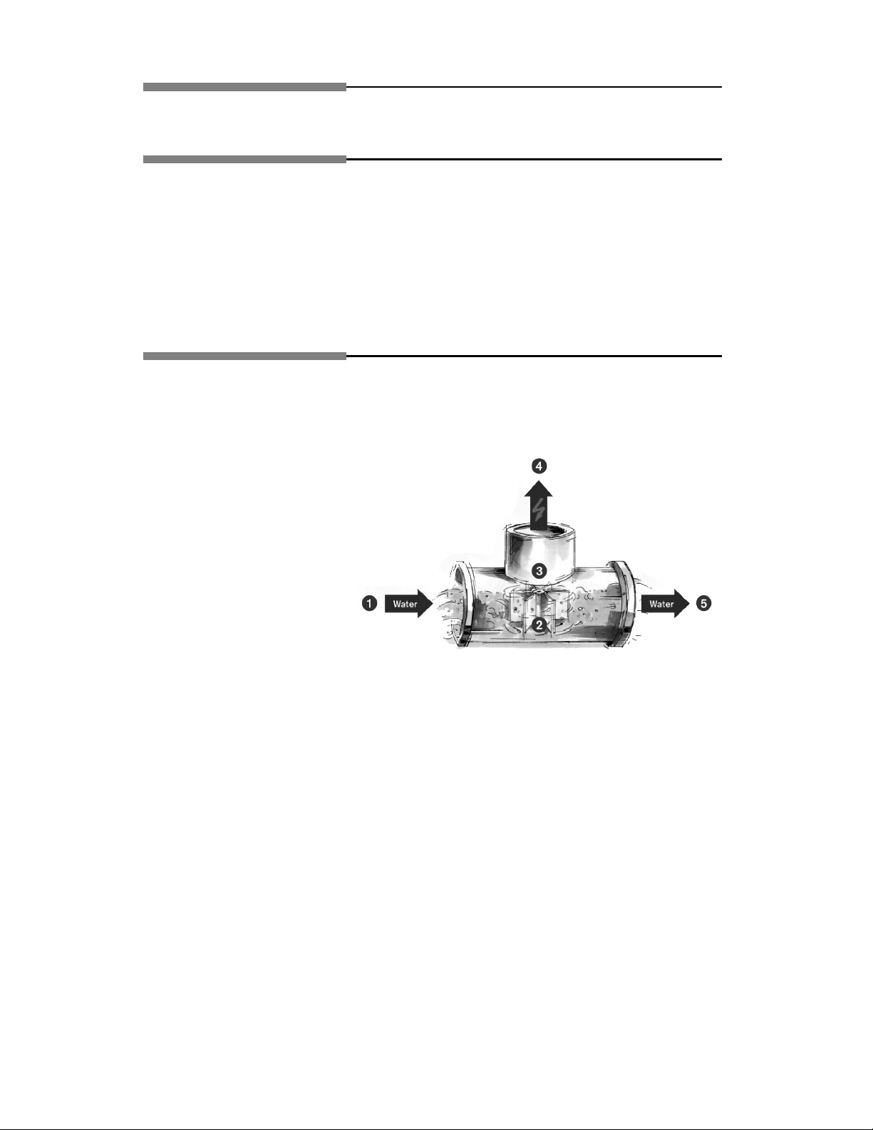
HydroPower Ignition is exclusive to Bosch.
HydroPower uses the energy created by water flow to ignite the burner and begin the heating process.
The unit only starts when a hot water tap is opened. Once hot water is no longer needed, the unit turns
itself off.
1. Water enters the Hydro
Dynamic Generator
2. The turbine spins with water
flow
3. A spark is generated by the
turbine
4. The spark ignites the main
burner
5. The water continues on to the
heat exchanger and is heated
External HydroPower
External HydroPower models are perfect for a
constant, reliable supply of hot water. The
HydroPower ignition provides endless hot
water at the flick of a tap, without the need of
power point.
Versatile
• LPG models are particularly popular in
country areas, where reticulated gas is not
available and there is no external power
point.
• They are able to operate in relatively low
water pressure areas and in low
temperature regions of Australia and New
Zealand using Bosch accessories.
Economical
• Only heating water when required by the
user, the Bosch range is extremely
economical to run.
Internal HydroPower
Limited space need not mean limited hot
water. The Bosch range of internal hot water
heaters are created specifically to go places
where storage units will not, and will provide
endless hot water.
Versatile
• Operable without a power point
• Compact design
• Flexible connections
• Caters for a wide range of applications and
needs
Economical
• Only heating water when required by the
user, the Bosch range is extremely
economical to run.
Page 4
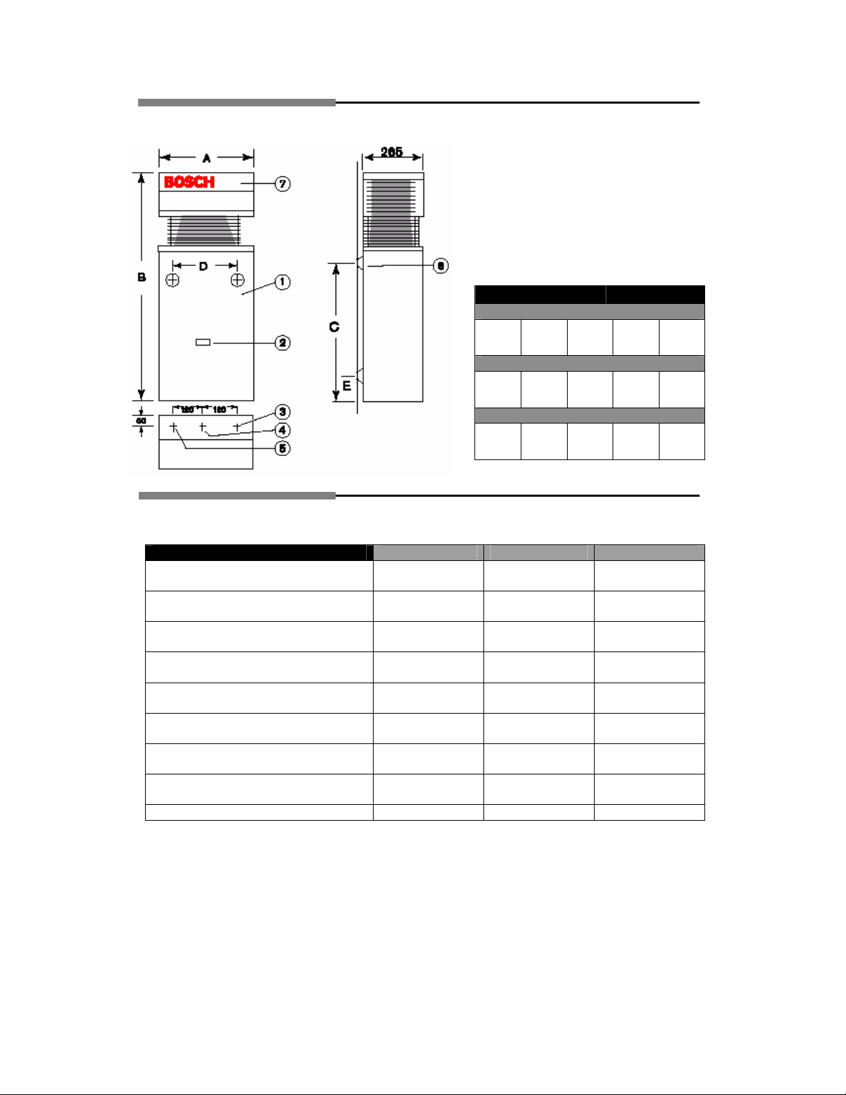
Product Diagram
1. Main Cover
2. Inspection Window
3. Cold Water Inlet
4. Gas Inlet
5. Hot Water Outlet
6. Mounting Point
7. Horizontal Flue
A B C D E
405mm 845mm 533mm 240mm 68mm
405mm 845mm 533mm 240mm
450mm 936mm 533mm 240mm
Dimensions
Product Characteristics
Model BOSCH 10H BOSCH 13H BOSCH 16H
Inlet Gas Pressure NG
Inlet Gas Pressure LPG
Burner Gas Pressure NG
Burner Gas Pressure LPG
NHGC
Maximum Water flow at 50°C rise
Maximum Water flow at 25°C rise
Minimum water flow rate
1.13 kPa 1.13 kPa 1.13 kPa
2.75 kPa 2.75 kPa 2.75 kPa
0.89 kPa 0.84 kPa 0.78 kPa
2.60 kPa 2.60 kPa 2.60 kPa
79 Mj/hr 104 Mj/hr 130 Mj/hr
5 l/min 6.5 l/min 8 l/min
10 l/min 13 l/min 16 l/min
3.5 l/min 3.5 l/min 3.5 l/min
10H
13H
16H
68mm
82mm
Note:
Your water heating appliance requires a hot water flow rate of 3.5 litres per minute
and above to operate.
Water fixtures with a flow rate of 7.5 litres per minute or higher and Shower Roses of
9 litres per minute or higher are recommended.
Your water heating appliance is not to be used on Solar, Spa or recirculation
systems.
4
Page 5

5
Operating Instructions
After installation, purge all water and gas pipes before operating.
Adjust appliance with only one tap operating.
Starting and shutting off the appliance
To switch the appliance on, turn the on/off switch to position "1"
To shut off the appliance, turn the on/off switch to position "0"
Green light on = Main burner on
Green light off = Main burner off
Red light flashing: Fault Indication
Output control
Page 6

6
Water Flow Adjustment
Turn anti-clockwise Water flow increases, temperature diminishes
Turn clockwise Water flow decreases, temperature increases.
Warning
If the appliance does not operate, burns with yellow flame, leaks water or a gas smell
is evident, turn off and contact the local gas authority, the manufacturer or an
authorised service person.
Freezing Weather
In areas where the atmospheric temperature may drop below 0°C the heater may be
drained to prevent damage by expansion of freezing water. For appliances installed
in locations where the temperature falls below 0°C and not less than -2°C for brief
periods, the installation of an EXOGEL expansion valve, part number H707 060 151,
will minimise the possibility of damage to the appliance.
This water heater MUST NOT be installed in areas where the temperature remains
below 0°C for extended periods.
CAUTION: It is recommended that for sanitary fixtures used
primarily for the purpose of personal hygiene that a temperature
control device be fitted (such as a tempering valve) as per
AS.3498
Page 7

7
Trouble Shooting
Symptom Possible Cause Solution
Appliance does not light Switch turned off
Hydrogenerator Jammed
Low Water Flow
Smell of gas Gas Leak Locate leak with soap
Low burner flame, water
does not heat up.
Low inlet gas pressure
Low burner pressure
Low water flow
Low flame
Low water temperature Water flow selector in
warm position
Low Gas pressure
Cross connection
Low water flow Low water pressure
Blocked water valve
Blocked shower rose or
tap aerator
Turn switch on
Clean hydrogenerator
Increase water flow >3.5
litres per minute
solution
Check supply regulator
and pipe size.
Check appliance regulator
Check water flow rate
Move slide control to high
Set flow rate to individual
need.
Check gas pressure
Disconnect hot outlet with
cold off. Correct
connection
Check and adjust
Clean filter
Clean
Care and Servicing of the Unit
We recommend that the appliance be inspected and cleaned by an authorised
person periodically, depending on the frequency and duration of its operation, but
never less than once in a two year period.
Page 8

8
10 Basic Steps for Installation
1. Check cold water supply pressures, min & max as per table below.
Model BOSCH 10H BOSCH 13H BOSCH 16H
Minimum Inlet
Pressure for
maximum
water flow
Minimum Inlet
Pressure for
minimum water
flow
Maximum Inlet
water pressure*
* If Inlet water pressure exceeds 800 kPa then a pressure reduction valve MUST be fitted.
Where the pressure reduction valve is less than 3 metres from the hot water unit then it must
be fitted in conjunction with a cold water expansion valve. Failure to comply with this
requirement may void the warranty. The preferable location for the pressure reduction valve is
at the water meter.
2. Connection sizing as per table below.
Hot & Cold Water
Natural Gas
L.P. Gas
3. Determine most suitable location for appliance. Install only on an external wall, as close as
possible to the most frequently used hot tap. If the unit is to be installed on a combustible
surface use a heat shield (P/N 9708061400.ZG1). Allow a minimum air gap of 10mm between
the flue and the heat shield.
4. Secure the water heater to wall using two appropriate fasteners.
5. Locate and connect cold and hot water piping to hot water appliance. Install a gate valve or a
full flow ball valve (fixed mechanism type) in cold water line. If the water supply pressure
exceeds 800 kPa, install a pressure reduction valve. If installing a reduction valve fit a cold
expansion valve between the reduction valve and the appliance. PRV=500 kPa Cold
Expansion=700 kPa. Refer to AS3500.1 and AS5601-2004 for the relevant pipe size.
NOTE: Service calls for incorrect pipe sizing will NOT be covered under warranty.
6. Test Inlet Gas Pressure while unit is running, adjust regulator to give values in table
below.
Model BOSCH 10H BOSCH 13H BOSCH 16H
Inlet Gas Pressure NG 1.13 kPa 1.13 kPa 1.13 kPa
Inlet Gas Pressure LPG 2.75 kPa 2.75 kPa 2.75 kPa
Natural Gas: With the gas supply turned off, remove sealing screw from inlet
pressure test point located on the left hand side of the gas section, attach manometer. Turn on
gas , open hot water tap fully and adjust gas pressure regulator to 1.13 kPa . Turn off gas and
water, remove manometer, replace sealing screw and test for soundness.
60 kPa 100 kPa 130 kPa
30 kPa 40 kPa 50 kPa
800 kPa 800 kPa 800 kPa
1/2" BSP Male
3/4" BSP Female
1/2" BSP Male
Page 9

9
LP Gas: No adjustment is provided at the appliance for inlet pressure, check cylinder
regulator and pipe sizing.
For LPG we recommend the installation of two or more supply cylinders and an auto change
over pressure regulator
7. Adjust Burner pressure. Turn off gas supply, loosen captive screw in burner pressure test
point, left hand side of burner manifold. Attach manometer, turn on gas and open hot water tap
fully, check pressure.
8. Minimum Gas Pressure Adjustment. Attach manometer to burner test point (see picture above)
Set water flow selector fully clockwise (hot position). Move gas slide to left side, single flame
symbol, open hot tap fully. Turn adjustment screw (Position C in picture below) located on
left hand side of gas valve at a 45° angle to correct pressure. Anti clockwise to decrease
minimum burner pressure.
Model BOSCH 10H BOSCH 13H BOSCH 16H
Burner Pressure LPG 0.64 kPa 0.64 kPa 0.64 kPa
Burner Pressure NG 0.30 kPa 0.30 kPa 0.30 kPa
9. Familiarise yourself with appliance operation and advise customer of operation.
10. Supply customer with these operating instructions and any other relevant paperwork
Page 10

10
Regulations
APPLIANCE LOCATION
(1) This water heater is approved for outdoor installation only.
(2) Do not install this water heater with any modification or alteration.
(3) Do not install this water heater indoors or in an enclosed space .
WARNING:
CLEARANCES FOR FLUE TERMINAL (front of heater)
The location of the flue terminal must comply with the clearances shown on this page. If you
are unsure about clearances not indicated here, in general refer to AS5601-2004, or your
local authority.
FLUE OUTLET MUST BE FREE FROM ANY COMBUSTIBLE MATERIAL.
Use as a guide only. Refer to AS5601 or local gas fitting rules
for specific locations
T = Flue Terminal M = Gas Meter Shaded area indicates
I = Mechanical air inlet P = Electrical meter or fuse box W = Window
Ref Item Minimum Clearance
Natural
a Below eaves, balconies and other projections
Appliances up to 50MJ/h input 300 200
Appliances over 50 MJ/h input 500 300
b From the ground, above a balcony or other surface 300 300
c From a return wall or external corner 500 300
d From a gas meter 1000 1000
e From an electricity meter or fuse box (P) 500 500
f From a drain pipe or soil pipe 150 75
g Horizontally from any building structure or obstruction facing a flue terminal 500 500
h From any other flue terminal, cowl, or combustion air intake 500 300
j Horizontally from an opening window, door, non-mechanical air inlet. Or other opening into
a building with the exception of sub floor ventilation
Appliances up to 150 MJ/h 500 300
Appliances over 150MJ/h input up to 200 MJ/h input 1500 500
Appliances over 200 MJ/h input 1500 1500
All fan assisted flue appliances in the direction of discharge 1500
k From a mechanical air inlet, including spa blower 1500 1000
n Vertically below an openable window, non-mechanical air inlet, or any other opening into a building
with the exception of sub-floor ventilation:
Space heaters up to 50 MJ/h 150 150
Other appliances up to 50 MJ/h 500 500
Appliances over 50 MJ/h and up to 150 MJ/h input 1000 1000
Appliances over 150 MJ/h input 1500 1500
prohibited area
draft
mm
Fan
assisted
Page 11

11
Overview of Warranty Conditions
What to do before contacting Bosch for Servicing assistance.
Check that the water is available to the unit (ie. No work being done on the mains)
Check that gas is available to the unit (ie. No work being done on the mains, LPG bottle not
empty).
Authorised Service Dealers
Please call 1300 307 037 to find your nearest service dealer.
Warranty
Your Bosch Hot Water unit is warranteed as follows:
For appliances used in domestic applications, ie. Normal hot water drawn from household
outlets, the warranty period is two (2) years parts and labour. Additionally, the heat exchanger
is covered for a period of ten (10) years (parts only).
For appliances used in commercial applications the warranty period is twelve (12) months
parts and labour including the heat exchanger.
The warranty period commences from the purchase date. Claims for warranty will only be
accepted upon suitable proof of purchase submitted to Robert Bosch (Australia) Pty. Ltd. or
an approved Bosch Service Agent authorised to carry out warranty repairs.
Purchasers Statutory Rights
The warranty terms set out below do not exclude any conditions or warranties which may be
mandatory implied by law, and your attention is drawn to the provisions of the Trade Practices
Act, 1974, and State legislation which confers certain rights upon consumers. The ROBERT
BOSCH (AUSTRALIA) PTY. LTD. Warranty supplements these.
Extract of Terms of Delivery and Sale
Warranty of products marketed by Robert Bosch (Australia) Pty. Ltd. Herein referred to as
RBAU.
a) RBAU warrants products marketed by it as free from faults and defects and having the
specified qualities according to the respective state of technology. Notwithstanding that
the products may have been sold by description or sample the products shall be accepted
by the Buyer even though alterations in design or construction have been generally
introduced between the date of contract and the delivery of the product.
b) The warranty shall be limited to the replacement or repair at the option of RBAU of any
defective products and of such parts of RBAU's products as have been damaged in
consequence of the defect despite proper treatment. Parts replaced will not be returned.
c) i) Repairs and maintenance shall not extend the warranty period of the appliance.
ii) If the product is located outside of the service agents area, the consumer shall be
responsible for the service agents travelling costs, and if necessary the expenses of freight,
packing and charges of a similar nature.
Without limiting the generality of these terms of delivery this warranty shall not apply to
products sold in the following cases:-i) If the products sold are repaired or altered by any third party without RBAU's consent.
ii) Where parts are not manufactured or sold by RBAU are used in a replacement or
repair.
iii) If products are not used with proper care and for the purpose for which they are sold
and in accordance with any specified instruction for use.
Page 12

12
iv) If changes occur in the condition or operational qualities of the products due to
incorrect storage or mounting or due to climatic or other influences.
v) In respect of faulty construction or defects due to the use of unsuitable materials if
such method of construction or use of material has been specified by the Buyer
vi) In respect of surface coating and glass damage.
vii) In respect of the replacement of parts when such replacements are part of the normal
maintenance, service or normal wear and tear.
No servant or authorised service agent has authority to add to or alter the terms of this
warranty.
Please Note: If a service call is requested and it is found that it is not a
manufacturing fault, you may be charged for the call even during the warranty
period.
.
 Loading...