

Page 1

Ú Instructions for connecting gas and gas conversion (for
After-Sales Service only)
HGV1E0U50M
HGV1D0U59M
HGV1D0V50M
HGV1F0U59M
HGVDA0Q50M
HGVDA0Q59M
HGW3ASQ50M
HGW3ASQ59M
HGV1F0V50.
HGV1F0V20.
HGVDF0V..S
HGW3FSV..S
HGV1F0U5.S
HGW3FSV50.
HGX5G7W30.
HGX5G7W8.S
HGVDF0X50S
HGX5G7W59S
HGX5H0W50M
HGX5H0W59M
HIZ5G7W50M
HIZ5G7W59M
HJY5G7.6.M
HJY5G7V6.S
HIZ5G7W59S
07
001230
Page 2

Ú Table of contents
Important information................................................................ 3
Choose which side of the appliance to connect the gas on (*
optional)................................................................................................3
Guidelines for ventilation.......................................................... 3
Gas connection.......................................................................... 4
Approved connections.......................................................................4
Liquefied gas connection (LPG) ......................................................4
Natural gas connection (NG)............................................................4
Electrical connection................................................................. 5
Conversion to a different gas type........................................... 6
Changing the gas type ......................................................................6
Parts for gas conversion ...................................................................6
Replacing the burner nozzles...........................................................6
Setting the burner bypass nozzles and a small flame.................7
Converting the appliance from liquid gas to natural gas............7
Converting the appliance from natural gas to liquid gas............7
Removing the control panel..............................................................7
Setting the bypass nozzles ...............................................................8
Fitting the control panel.....................................................................8
Replacing the oven gas burner (optional) .....................................8
Leak test and function test ....................................................... 9
Check the gas connection ................................................................9
Checking the burner nozzles............................................................9
Checking the bypass valves.............................................................9
Checking the oven burner nozzle (option).................................. 10
Check the grill burner nozzle (option) ......................................... 10
Correct flame formation .......................................................... 10
Burners .............................................................................................. 10
Oven ................................................................................................... 10
Technical data – Gas ............................................................... 11
Appliance categories............................................................... 11
Ú Instructions for connecting gas and gas conversion (for After-Sales Service only)
2
Page 3
Important information
The appliance must only be converted from one gas type to
another by authorised personnel who have received
appropriate training. The procedure must always be carried
out in accordance with the instructions in this manual.
Incorrect connection and incorrect settings configuration
may damage the appliance. The manufacturer accepts no
responsibility for failure to connect or configure the
appliance correctly.
Always observe the symbols on the rating plate. If there is no
symbol that is relevant to your country, comply with the
technical guidelines in force in your country when configuring
the appliance.
Find out which gas type and which gas pressure your local gas
supply network uses before installing the appliance. Make sure
that all settings have been configured correctly before starting
to use the appliance.
Always observe local and national guidelines and regulations.
All the connection data you need can be found on the rating
plate to the right of the appliance door.
Enter the following data in the table:
Product number (E no.)
Production number (FD)
Enter the factory settings for the gas type/gas pressure in the
table and then add the applicable gas type/gas pressure
settings for once conversion has been carried out.
E no. FD
After-sales service
Gas type/gas pressure
This data can be found on the
rating plate
Gas type/gas pressure
Data following gas conversion
O
: Risk of gas escape!
■ After connecting the appliance to the gas supply, always
check the connection for leak tightness. The manufacturer
accepts no responsibility for the escape of gas from a gas
connection which has been previously tampered with.
Risk of gas leak!
■ Do not move the appliance by pulling on the gas pipe
(collector). This could damage the gas pipe.
Risk of gas leak!
■ The appliance must not be moved once it has been installed.
If you do move the appliance once it has been installed,
check that the connection is leak-tight.
Switch off the power and gas supply before carrying out any
work.
This appliance must not be installed on boats or in vehicles.
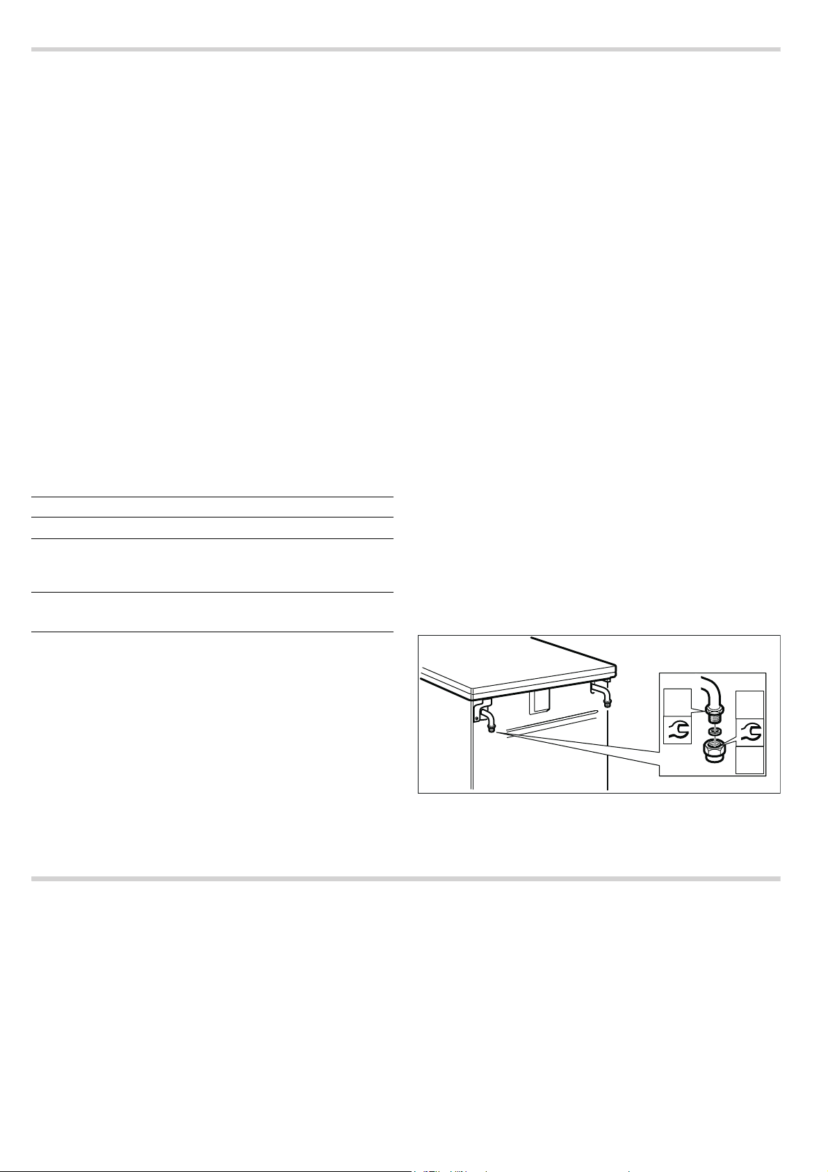
Choose which side of the appliance to connect the gas on (* optional)
The gas supply to the appliance can be connected on the left
or right. The side on which the gas supply is connected can be
changed if necessary.
Connect the main gas supply.
If you change the side on which the gas supply is connected,
the gas connection piece on the side that is not being used
must be sealed with a blind plug.
To do this:
1. Place the new seal in the blind plug. Make sure the seal is
seated correctly.
2. Secure the gas connection piece to the appliance using a 22
mm spanner and place the blind plug onto the connection
piece using a 24 mm spanner.
Once the side on which the gas supply is connected has been
changed, check that the connection is leak-tight. See the
section entitled "Leak testing" for more information about this.
Caution!
After converting the appliance from one gas type to another,
the new gas type must be indicated on the rating plate.Use a
gas conversion label to do this. The gas type is marked with an
asterisk (*) on the label. The label detailing the gas type
(marked with an asterisk (*)) to which the appliance has been
converted must be adhered in the designated place on the
rating plate.
The changes made to the appliance and the type of connection
are essential to enabling the appliance to work safely and in
accordance with the relevant regulations.
Guidelines for ventilation
This appliance must only be installed in a room that is
sufficiently ventilated.
If the total power for all gas appliances is below 11 kW, then
this requirement is met if the installation room has a volume of
over 15 m³ and at least one door leading outside or one
window that can be opened.
If the total power for all gas appliances is above 11 kW, then
this requirement is met if the installation room has a volume of
over 2 m³ per kW and at least one door leading outside or one
window that can be opened. Furthermore, an exhaust extractor
hood or a controlled domestic ventilation system (no
recirculated air operation) should be present and should have a
6:
Note: Use a torque wrench to connect the appliance.
* Option: Only valid for some models.
minimum flow volume of 15 m³/h for each kW of total power for
all gas appliances. Appropriate supply air openings must be
present.
Note: In some countries, the requirements for minimum room
volume vary. Find out information on this from your after-sales
service.
6:
1P
3
Page 4
Gas connection
Approved connections
These instructions apply only when the appliance is set up in
countries that are indicated on the rating plate.
If the appliance is set up, connected and used in a country that
is not indicated on the rating plate, installation and assembly
instructions must be used that contain data and information on
the valid connection conditions in the relevant country.
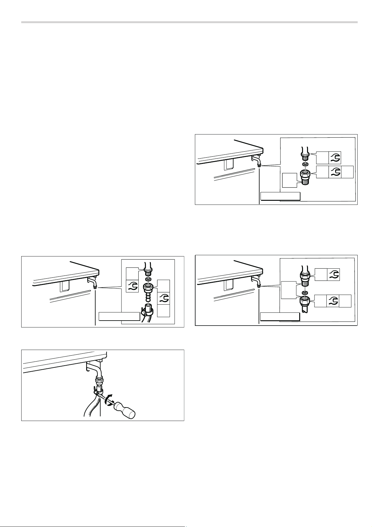
Liquefied gas connection (LPG)
Caution!
Observe the specific guidelines for each country.
If liquid gas (LPG) is used, the gas supply should be connected
via a gas hose or a fixed connector.
Important information on using a gas hose:
■ Use a safety gas hose or a plastic gas hose (8 or 10 mm in
diameter).
■ It must be attached to the gas connection using an approved
connecting device (e.g. a hose clamp).
■ The hose must be short and completely leak-tight. The hose
must not be longer than 1.5 m. Observe the applicable
guidelines.
■ The gas hose must be replaced once a year.
1. Place the new seal in the connection piece. Make sure the
seal is seated correctly.
2. Secure the gas connection piece to the appliance using a 22
mm spanner and place the connection piece into the
connection piece using a 24 mm spanner.
Natural gas connection (NG)
If natural has (NG) is used, the gas supply should be
connected via a gas pipe or a safety gas hose with threaded
fittings at both ends.
Connection in accordance with EN ISO 228 G
228 G
^ )
1. Place the new seal in the connection piece. Make sure the
seal is seated correctly.
2. Secure the gas connection piece to the appliance using a 22
mm spanner and place the connection piece into the
connection piece using a 24 mm spanner.
*ê
1***
3. Place the new seal into the gas pipe or safety gas hose.
Make sure the seal is seated correctly.
4. Secure the connection piece using a 24 mm spanner. Use a
24 mm spanner to place the threaded fitting of the gas pipe
or safety gas hose on the connection piece and tighten it
firmly.
^ (TS EN ISO
6:
6:
1P
6:
6:
/3***
3. Fit the safety gas hose and use a pipe union or cable clamp
to tighten it securely.
4. For information on how to carry out leak testing, see the
section entitled "Leak testing". Open the gas connection shut-
off.
Note: Use a torque wrench to connect the appliance.
1P
6:
*ê
6:
1P
1***
5. For information on how to carry out leak testing, see the
section entitled "Leak testing". Open the gas connection shut-
off.
: Risk of gas leak!
When connecting the gas pipe or safety gas hose, do not
tighten the gas connection piece on the appliance using a 22
m spanner. This may damage the connection piece.
Notes
■ *G^: EN ISO 228 G^ (TS EN ISO 228 G^)
■ Use a torque wrench to connect the appliance.
4
Page 5

Connection in accordance with EN 10226 R
10226 R
1. Place the new seal in the connection piece. Make sure the
2. Secure the gas connection piece to the appliance using a 22
^ )
seal is seated correctly.
mm spanner and place the connection piece into the
connection piece using a 24 mm spanner.
5ê
1***
^ (TS 61-210 EN
6:
6:
1P
3. Secure the connection piece using a 24 mm spanner. Use a
24 mm spanner to place the threaded fitting of the gas pipe
or safety gas hose on the connection piece and tighten it
firmly.
6:
5ê
6:
1***
4. For information on how to carry out leak testing, see the
section entitled "Leak testing". Open the gas connection shut-
off.
1P
: Risk of gas leak!
When connecting the gas pipe or safety gas hose, do not
tighten the gas connection piece on the appliance using a 22
m spanner. This may damage the connection piece.
Notes
■ *R^: EN 10226 R^ (TS 61-210 EN 10226 R^)
■ Use a torque wrench to connect the appliance.
Electrical connection
Only licensed specialists may connect the appliance.It is
important that you comply with the requirements of your
electricity supplier.
The appliance is designed to operate at 220-240 V. A 16 A
fuse is required for connection.
Any damage arising from the appliance being connected
incorrectly will invalidate the warranty.
Caution!
If the supply cord is damaged, it must be replaced by the
manufacturer, its service agent or similarly qualified persons in
order to avoid a hazard.
■ The appliance must be disconnected from the power supply
whenever installation work is being carried out.
■ The appliance fulfils the requirements of protection class I
and may only be connected to an earthed socket.
W
Notes
1 Yellow and green
2 Brown
3Blue
>
E
5
Page 6

Conversion to a different gas type
Changing the gas type
■ Change the gas connection piece.
■ Change the burner nozzles.
■ The bypass nozzles of the burner taps will need to be
adjusted depending on the gas setting configured at the
factory.
■ If fitted, the nozzles for the oven burner and grill burner must
also be changed.
The numbers on the burners refer to their diameter. You can
find more information about which gas types can be used with
the appliance and the appropriate gas nozzles in the section
entitled "Technical specifications – Gas".
After conversion
■ Always test for leaks after converting the appliance to a
different gas type. See the section entitled "Testing for leaks"
for details.
■ The burning must be checked after the product has been
converted to a different gas type. See the section entitled
"Correct burning" for details.
■ Enter the new gas type and the new gas pressure in the
table. See the section entitled "Important information".
Parts for gas conversion
The parts required for the gas conversion procedure described
are given below.
To find out the correct nozzle diameter, see the table entitled
"Technical data – Gas".
Always use a new seal.
The gas connecting piece may vary depending on the gas type
and the regulations in force in your country.
(*) A gas connection must never be made without these parts.
(*) Connecting piece for liquid gas
(LPG: G30, G31)
Connection piece
Replacing the burner nozzles
1. Make sure all the knobs on the control panel are turned off.
2. Close the gas connection shut-off.
3. Remove the pan supports and the burner parts.
4. Removing the burner nozzles
6:
6:
Bypass nozzle
Burner nozzle
(*) Seal
(*) Connecting piece for natural
gas
(NG: G20, G25)
TS 61-210 EN 10226 R
^
EN 10226 R^
(*) Connecting piece for natural
gas
(NG: G20, G25)
TS EN ISO 228 G
^
EN ISO 228 G^
5. Look up the burner nozzles in the table. You can find
information about this in the section entitled "Technical data –
Gas".
6. Position the new burner nozzles on the corresponding
burners and screw them in place. (Tightening torque 4 Nm)
If the burner nozzles have been replaced, check that they are
not leaking. You can find information about this in the section
entitled "Testing for leaks".
6
Page 7

Setting the burner bypass nozzles and a small flame
The bypass nozzles are used to set the minimum flame height
for the burners.
Preparation
Close the gas connection shut-off.
: Risk of electric shock!
Disconnect the appliance from the mains.
1. Make sure the knobs on the control panel are turned off.
2. Remove the knobs one by one by holding them firmly against
the control panel and pulling them towards you slightly.
2. Remove the pan supports and the burner parts.
3. Remove all burner connection screws on the hob.
Converting the appliance from liquid gas to natural gas
If the appliance is being converted from liquid gas
(LPG: G30, G31) to natural gas (NG: G20, G25):
Turn all the bypass nozzles in the appliance anti-clockwise by
half a turn. You can find information about this in the section
entitled "Removing the control panel".
Then carry out the steps described in the "Setting the bypass
nozzles" section.
Then carry out the steps described in the "Fitting the control
panel" section.
Converting the appliance from natural gas to liquid gas
If the appliance has been set to natural gas (NG: G20, G25)
and needs to be converted to liquid gas (LPG: G30, G31):
Fully tighten all the bypass nozzles in the appliance by turning
them clockwise. See the section entitled "Removing the control
panel".
Then carry out the steps described in the "Setting the bypass
nozzles" section.
Then carry out the steps described in the "Installing the control
panel" section.
Removing the control panel
1. There may be some differences, depending on the type of
appliance.
If the appliance has an upper cover, remove this. To remove
the cover, open it fully, hold it by the sides with both hands
and pull it upwards. The upper cover will come loose. Ensure
that you do not lose the hinges (optional).
4. There may be some differences, depending on the type of
appliance.
If screws are present on the left- and right-hand hinge
fastener, remove these (optional).
If there is a splash guard, remove the screws (1). Remove the screws in the hob top below the splash guard (2) (optional).
5. Lift up the hob top upwards by the burner hubs, then pull it
forwards.
7
Page 8

6. Take the knobs off the hob top by pulling them towards you.
Remove the screws in the corners of the front panel.
7. Remove the screws that become visible after you remove the
buttons from the front panel.
8. If an upper appliance cover is available, hold this on both
sides and lower it vertically into the holder (optional).
9. Refit the pan supports.
10.Carefully insert the knobs.
11.At this stage, you must check that the burners are burning
correctly. You can find information about this in the section
entitled "Correct burner behaviour".
12.Check whether the appliance is working correctly.
Replacing the oven gas burner (optional)
Preparation
Make sure all the knobs on the control panel are turned off.
Close the gas connection shut-off.
: Risk of electric shock!
Disconnect the appliance from the mains.
Replacing the nozzle for the lower oven gas burner (optional)
1. On the rear cover, loosen the plastic screw on the power
cord's fixing parts.
2. Remove the screws on the rear cover and take the cover off.
3. Remove the two screws on the nozzle holder for the lower
oven burner and carefully take the nozzle holder out.
4. Remove the nozzle from the nozzle holder using a 7 mm box
spanner.
Setting the bypass nozzles
1. Use a slotted screwdriver (no. 3) to set the bypass nozzles
for the gas type that is going to be used, following the
instructions in the section entitled "Converting from LPG to
natural gas" or "Converting from natural gas to LPG".
2. At this stage, it is important to test for leaks. See the section
entitled "Testing for leaks".
Fitting the control panel
To reassemble, proceed in the reverse order of disassembly.
There may be some differences, depending on the type of
appliance.
1. Take hold of the control panel with both hands and carefully
fit it into place. Make sure that you do not damage the cables
and that the connections do not come loose.
2. Insert the screws under the buttons on the front panel.
3. Insert the screws in the corners of the front panel.
4. Push the hob top backwards and slowly insert it.
5. If you have to insert the screws on the left- and right-hand
hinge brackets, insert these. (optional)
If there is a splash guard, insert the screws in the hob top (2).
Insert the splash guard and attach the screws. (1) (optional)
6. Insert the burner connection screws.
7. Put the burner bases in place, positioning them by size, and
make sure that the ignition plugs are inserted into the
opening at the edge of each burner base. Place the burner
caps in the centre of the burner bases of the corresponding
size.
5. Select the appropriate nozzle from the table depending on
the new gas type. You can find information about this in the
section entitled "Technical data – Gas".
6. Put the new nozzle in place and tighten. (Tightening torque 4
Nm)
7. At this stage, it is important to test for leaks. See the section
entitled "Testing for leaks" for instructions on how to do this.
8. Carefully fit the nozzle holder into place. Insert the screws.
9. At this stage, it is important to test for leaks. See the section
entitled "Testing for leaks" for instructions on how to do this.
10.Fit the rear cover and insert the screws.
11.On the rear cover, tighten the plastic screw on the power
cord's fixing parts.
12.At this stage, it is important to check that the burner is
burning correctly. You can find information about this in the
section entitled "Correct burner behaviour".
8
Page 9

Replacing the nozzle for the grill burner (optional)
1. Open the oven door.
2. Remove the two fastening screws on the grill burner nozzle
holder.
3. On the rear cover, loosen the plastic screw on the power
cord's fixing parts.
4. Remove the screws on the rear cover and take the cover off.
5. Carefully take the grill burner nozzle holder out.
6. Remove the nozzle for the grill burner using a 7 mm box
spanner.
7. Select the appropriate nozzle from the table depending on
the new gas type. You can find information about this in the
section entitled "Technical data – Gas".
8. Put the new nozzle in place and tighten. (Tightening torque 4
Nm)
9. At this stage, it is important to test for leaks. See the section
entitled "Testing for leaks" for instructions on how to do this.
10.Carefully fit the grill nozzle holder into place.
11.Insert the two fastening screws on the nozzle holder.
12.At this stage, it is important to test for leaks. See the section
entitled "Testing for leaks" for instructions on how to do this.
13.Fit the rear cover and insert the screws.
14.On the rear cover, tighten the plastic screw on the power
cord's fixing parts.
15.At this stage, it is important to check that the burner is
burning correctly. You can find information about this in the
section entitled "Correct burner behaviour".
Leak test and function test
: Risk of explosion!
Avoid sparking. Do not use an open flame.
Perform the leak test only with a suitable leakage spray.
In the event of a gas leak
Shut off the gas supply.
Ensure that the room affected is well ventilated.
Check the gas and valve connections again. Repeat the leak
test.
The leak test must be performed by two people, in accordance
with the following instructions.
Check the gas connection
1. Open the gas supply.
2. Spray the gas connection with a leakage spray.
If small bubbles or foam form, indicating a gas leak, follow the
instructions in the section entitled "In the event of a gas leak".
Perform the same steps for the part closed with the blind plug.
Checking the burner nozzles
1. Open the gas supply.
Carry out the leak test separately for each nozzle.
2. Carefully close the hole in the burner nozzle to be checked
using your finger or a suitable device.
3. Spray the nozzle with a leakage spray.
4. Press the function selector and turn it anti-clockwise. This
supplies the nozzle with gas.
If small bubbles or foam form, indicating a gas leak, follow the
instructions in the section entitled "In the event of a gas leak".
Checking the bypass valves
1. Open the gas supply.
Carry out the leak test separately for each bypass screw.
2. Carefully close the hole in the burner nozzle to be checked
using your finger or a suitable device.
3. Spray the nozzle in the burner to be checked with a leakage
spray.
4. Push the control knob and turn it anti-clockwise. This supplies
the nozzle with gas.
If small bubbles or foam form, indicating a gas leak, follow the
instructions in the section entitled "In the event of a gas leak".
9
Page 10

Checking the oven burner nozzle (option)
1. Open the gas supply.
2. Carefully close the hole in the oven burner nozzle using your
finger or a suitable device.
3. Spray the nozzle with a leakage spray.
4. Press the function selector and turn it anti-clockwise. This
supplies the nozzle with gas.
If small bubbles or foam form, indicating a gas leak, follow the
instructions in the section entitled "In the event of a gas leak".
Correct flame formation
Check the grill burner nozzle (option)
1. Open the gas supply.
2. Carefully close the hole in the grill burner nozzle using your
finger or a suitable device.
3. Spray the nozzle with a leakage spray.
4. Turn the oven function selector clockwise. This supplies the
nozzle with gas.
If small bubbles or foam form, indicating a gas leak, follow the
instructions in the section entitled "In the event of a gas leak".
Burners
The burning and soot formation of each burner must be
checked after the product has been converted to a different
gas type.
If there is a problem, compare the nozzle values with the values
in the table.
1. Ignite the gas burners in accordance with the instructions in
the operating manual.
2. Set the burner head to a small flame.
Check whether the flame safety system is working by keeping
the flame at the "small flame" setting for one minute.
3. Check that the burners are burning correctly with both large
and small flames. The flame should burn evenly and steadily.
4. Turn the burner knob back and forth quickly between the
large flame setting and the small flame setting. Repeat this
process several times. The gas flame must not flicker or go
out.
Oven
Bottom gas burner or gas grill burner (optional)
1. Ignite the lower gas burner in accordance with the
instructions in the operating manual.
2. Open the oven door and observe the flame.:
The flame must burn evenly. (Failure may occur during the
first few minutes. However, the flame must stabilise after a
few minutes.)
3. Switch on the appliance for a few minutes to check whether
the thermocouple becomes sufficiently warm.
If required, check the settings and, in the event of a fault,
ensure that the setting for the bypass nozzle on the burner is
correct.
10
Page 11

Technical data – Gas
Different types of gas and the corresponding values are listed
here.
Gas type mbar Nozzle Burner type Power
(kW)
1,75 ≤ 0,9 167 l/h
4,2 ≤ 2,6 399 l/h
1,75 ≤ 0,9 127 g/h
4,2 ≤ 2,6 306 g/h
1,75 ≤ 0,9 127 g/h
3,4 ≤ 2,6 248 g/h
Natural gas
NG
G20
Liquid gas
Butane
Propane
LPG
G30
Liquid gas
Butane
Propane
LPG
G30
(mm) Bypass G20 (l/h) G30 (g/h)
20 1,16 0,78 High output burner 3,0 ≤ 1,3 285 l/h
0,97 0,60 Standard output
burner
0,72 0,52 Economy burner 1,0 ≤ 0,55 95 l/h
1,48 0,94 Wok burner 4,0 ≤ 1,7 381 l/h
1,48/ 0,70 0,92/ 0,57 Dual-flame wok
burner
1,47 0,76 Oven burner 4,2 - 399 l/h
1,30 - Grill burner 3,1 - 295 l/h
28 - 30 0,85 0,49 High output burner 3,0 ≤ 1,3 218 g/h
0,65 0,40 Standard output
burner
0,50 0,32 Economy burner 1,0 ≤ 0,55 73 g/h
1,00 0,59 Wok burner 4,0 ≤ 1,7 291 g/h
0,95/ 0,44 0,57/ 0,30 Dual-flame wok
burner
0,90 0,56 Oven burner 4,2 - 306 g/h
0,85 - Grill burner 3,1 - 226 g/h
50 0,75 0,49 High output burner 3,0 ≤ 1,3 218 g/h
0,58 0,40 Standard output
burner
0,43 0,32 Economy burner 1,0 ≤ 0,55 73 g/h
0,80 0,59 Wok burner 3,4 ≤ 1,7 248 g/h
0,68/ 0,43 0,57/ 0,30 Dual-flame wok
burner
0,88 0,56 Oven burner 4,4 - 321 g/h
0,73 0,55 Grill burner 3,1 ≤ 1,7 226 g/h
Power
min. (kW)
Max. consumption
Your appliance must be operated at these pressure values. All
information on the rating plate refers to these pressure values.
The manufacturer does not accept any liability for operability,
power of the appliance or for other risks if the appliance is
Appliance categories
Country Category P (mbar)
RU, BY, KZ, AM, KG II 2H3B/P 2000 тта–3000 тта
UA II 2H3B/P 20 - 28 - 30
MA I 3+ 28 - 30/37
AE, LB, JO II 2H3B/P 20 - 28 - 30
EG II 2H3+ 20 - 28 - 30/37
operated at pressure values other than those values specified
for the appliance.
Note: If you are operating the appliance with liquefied gas, use
a gas pressure regulator. The pressure regulator must be
connected and maintained by a licensed technician.
11
Page 12

3PCFSU#PTDI)BVTHFSÉUF(NC)
$BSM8FSZ4USBF
.ßODIFO
(FSNBOZ
XXXCPTDIIPNFDPN
*9001456465*
9001456465
 Loading...