

Bosch HEZBS301, HGZBS301 Installation Guide

INSTALLATION MANUAL
For Low Backguard Trim
Models/
Modèles/
Modelos:
MANUEL D’INSTALLATION
Pour Garniture de Dosseret Bas
MANUAL DE INSTALACIÓN
Moldura de la placa antisalpicaduras
inferiorDosseret Bas
HEZBS301
HGZBS301


Safety Definitions
9 WARNING:
If the information in this manual is not followed exactly, a
fire or explosion may result causing property dama ge ,
personal injury or death.
-- Do not store or use combustible materials,
gasoline or other flammable vapors and liquids
in the vicinity of this or any other appliance.
-- WHAT TO DO IF YOU SMELL GAS
• Do not try to light any appliance.
• Do not touch any electrical switch.
• Do not use any phone in your building.
• Immediately call your gas supplier from a
neighbor’s phone. Follow the gas supplier’s
instructions.
• If you cannot reach your gas supplier, call
the fire department.
-- Installation and service must be perf ormed by a
qualified installer, authorized service agency or
the gas supplier.
WARNING
9
This indicates that death or serious injuries may
occur as a result of non-observance of this warning.
CAUTION
9
This indicates that minor or moderate injuries may
occur as a result of non-observance of this warning.
NOTICE: This indicates that damage to the appliance or
property may occur as a result of non-compliance with this
advisory.
Note: This alerts you to important information and/or tips.
9001050650 Rev A English 1
9 IMPORTANT SAFETY INSTRUCTIONS
READ AND SAVE THESE INSTRUCTIONS
9 WARNING:
If the information in this manual is not followed
exactly, property damage or personal injury may
result.
Read the instructions completely before attempting
one of these procedures.
Installation of a Low Backguard requires access to
the mounting screws on the back and sides of the
range. If electrical or gas connections prevent access
to the screws, contact a qualified technician before
proceeding. Your dealer can recommend a qualified
technician.
Appliance Handling Safety
9 CAUTION
• The range is heavy and requires at least two
persons or proper equipment to move.
• Hidden surfaces may have sharp edges. Use
gloves and caution when reaching behind or
under appliance.
Do not move the range by the oven door handle. You may
wish to remove the oven door for easier handling. See the
Installation Manual for your range for more information.
Turn power OFF at the service pan el. Lock service panel to
prevent power from being turned ON acc ide n tally.
Refer to range data plate for more information. See the
Installation Manual for your range for the data plate
location.
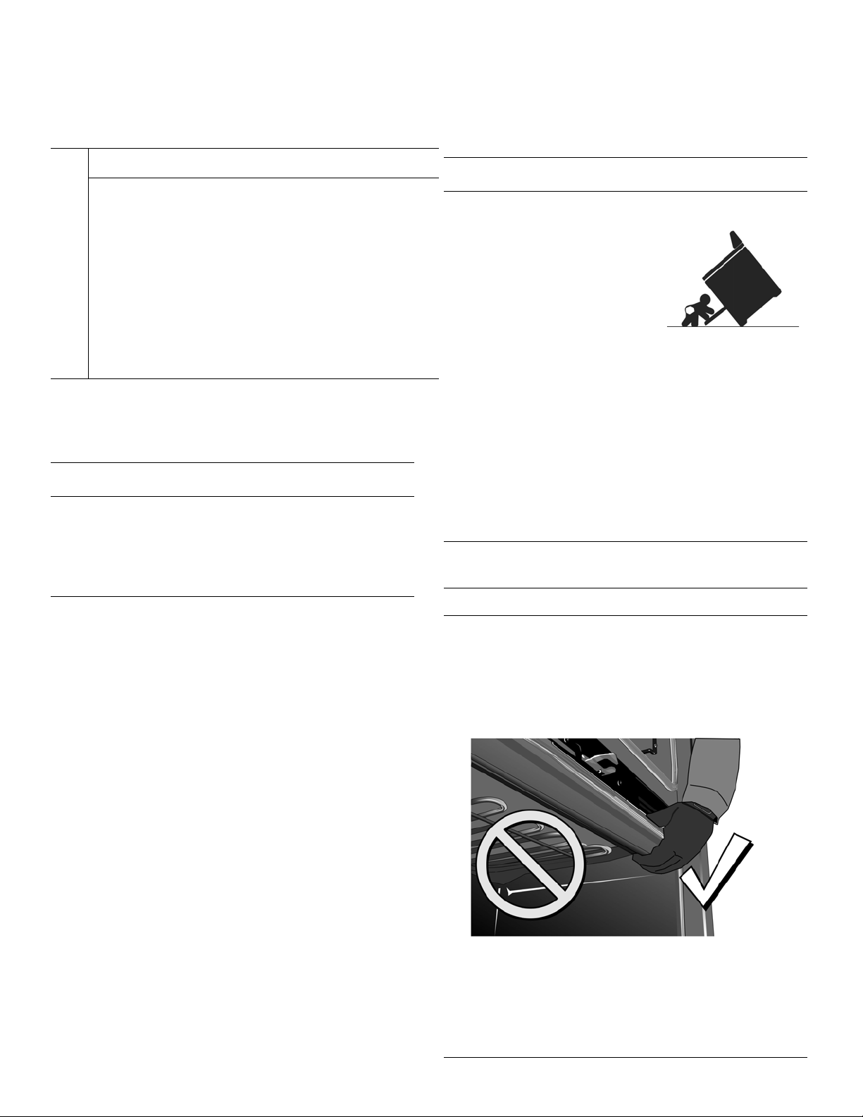
9 WARNING
TIP OVER HAZARD!
A child or adult can tip the
range over and be killed.
Verify that the anti-tip
bracket is securely installed.
Ensure the anti-tip bracket
is engaged whenever the
range is moved to a new
location.
Do not operate the range without the anti-tip bracket
in place. Failure to follow the instructions in this
manual can result in death or serious burns to
children and adults.
Check for proper installation and use of the anti-tip
bracket. Carefully tip the range forward pulling from
the back to ensure that the anti-tip bracket engages
the range leg and prevents tip-over. Range should
not move more than 1” (25 mm).
NOTICE
Proper Handling Technique
To avoid risk of damage to the range oven door, do
not lift, push, or pull the range by holding the door
handle. Take care not to touch the oven heating
element also located at the top of the oven cavity,
just behind the ridged area.
Note: It is recommended to wear gloves and long
sleeves to protect hands and forearms from
abrasion and potential scratches during the sliding
process. It is also recommended to take off watches
and jewelry and to wear work shoes during
installation for foot protection.
9001050650 Rev A English 2
Low Backguard Installation
Procedure for a Gas Slide-InRange (Low Backguard, Gas
HGZBS301)
Tools Needed
• Torx T20 screwdriver
•gloves
Preparation
9 IMPORTANT!
Can you slide the range out enough to have access to the
rear and side screws of the rear louver cover and trim?
• If you can slide the range out, continue with the
procedure,
• If you cannot slide the range out, contact a qualified
service person to disconnect the gas or electrical
connections that prevent the range from being pulled
out before proceeding.
• Read the Tip Over W arning in the Safety sectio n of this
manual. Be aware of this when the range has been
pulled out of the anti-tip bracket for this installation.
Procedure
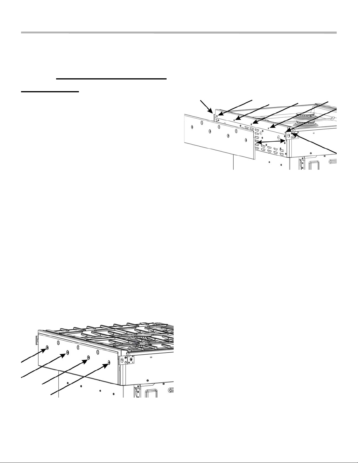
5. Remove the cooktop grates.
6. Remove the screws holding the trim (five screws on the
back and one screw on each end). Save these screws
for installation of the Low Backguard.
Figure 2: Trim screw locations (louver cover removed)
7. Rotate the trim forward, slide slightly to the front, and
lift it off.
8. Place the Low Backguard in position A (See Figure 3:
Low Backguard placement) and then move it to
position B (engaging the alignment device 1) (the
appearance of the devices may not be exactly as
shown). Rotate the Low Backguard to a vertical
position, aligning hole 2 with the holes at 3 on both
sides of the range.
1. Confirm that the range and cooktop grates are cool
enough to be comfortably touched at the rear.
2. Slide the range out enough to access the rear louver
cover mounting screws.
3. Remove the four screws holding the rear louver cover.
Save these screws to reattach the louver cover.
Figure 1: Rear louver cover screw locations
4. Lift the louver cover out of the slots holding it in place.
Note the slot locations for later.
9001050650 Rev A English 3
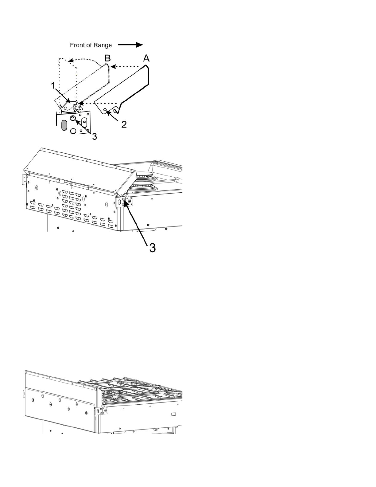
Figure 3: Low Backguard placement
9. Secure the Low Backguard with one screw at each end
(through holes 2 and 3) and hold the Low Backgu ard in
a vertical position while securing the five screws in the
back.
10. Plac e th e re ar louv er cove r into its slots and secure
with four screws.
11. Replace the cooktop grates.
12. If ne cessa r y, have a qualified service person reattach
electrical or gas connections.
13. Slide the range back into position.
Figure 4: Low Backguard in position
English 4 9001050650 Rev A
Procedure for an Electric or
Induction Slide-In-Range (Low
Backguard, Electric and
Induction HEBZS301)
Tools Needed
• Torx T20 screwdriver
•gloves
Preparation
9 IMPORTANT!
Can you slide the range out enough to have access to the
rear and side rear trim screws?
• If you can slide the range out, continue with the
procedure,
• If you cannot slide the range out, contact a qualified
service person to disconnect the electrical connections
that prevent the range from being pulled out before
continuing with the procedure.
• Read the Tip Over W arning in the Safety Section of this
manual. Be aware of this when the range has been
pulled out of the anti-tip bracket for this installation.
Figure 6: Low Backguard placement
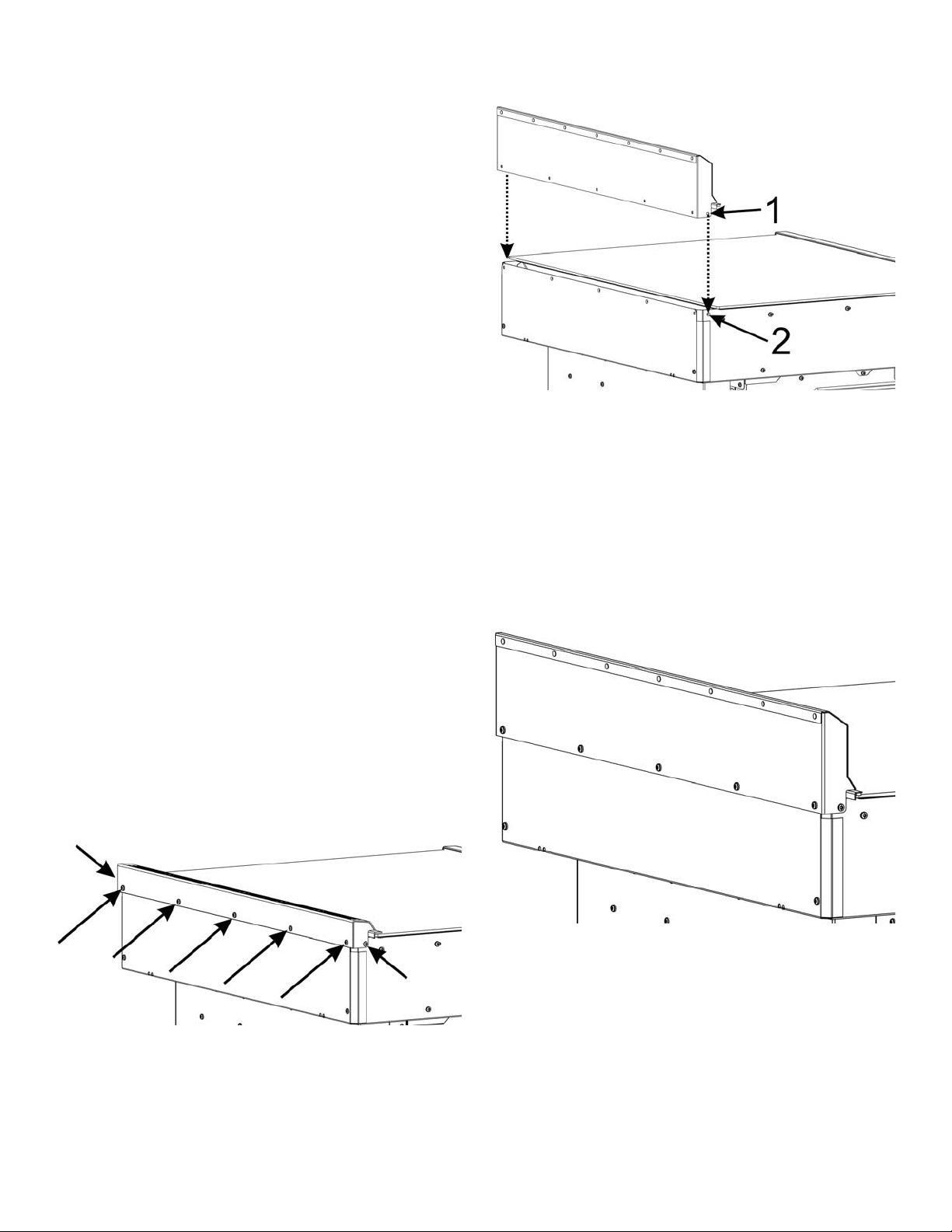
6. Secure the Low Backguard with one screw at each end
and then hold the Low Backguard in a vertical position
while securing the 5 screws in the back.
7. If necessary, have a qualified service person reattach
the electrical connections.
8. Slide the range back into position.
9. End of procedure.
Procedure
1. Confirm that the range is cool enough to be
comfortably touched at the rear.
2. Slide the range out enough to access the trim mounting
screws.
3. Remove the screws holding the trim (five screws on the
back and one screw on each end). Save these screws
for installing the Low Backguard.
Figure 5: Trim screw locations
4. Lift the trim off.
5. Lower the Low Backguard into place, aligning the holes
at 1 with the holes at 2 on both sides of the range.
Figure 7: Low Backguard in position
9001050650 Rev A English 5

English 6 9001050650 Rev A
 Loading...